Bio-Tek ELx808 User manual

Operator’s Manual
Absorbance Microplate Reader
ELx808™


ELx808™
Absorbance Microplate Reader, All Models
Operator’s Manual
April 2013
© 2013
Part Number 7341000
Revision P
BioTek®Instruments, Inc.

ii | Preface
BioTek Instruments, Inc.
Notices
BioTek® Instruments, Inc.
Highland Park, P.O. Box 998
Winooski, Vermont 05404-0998 USA
All Rights Reserved
© 2013, BioTek®Instruments, Incorporated. No part of this publication may be
reproduced, transcribed, or transmitted in any form, or by any means electronic or
mechanical, including photocopying and recording, for any purpose other than the
purchaser’s use without written permission of BioTek Instruments, Inc.
Trademarks
BioTek®is a registered trademark, and ELx808™, 4-Zone™ and Gen5™ are trademarks
of BioTek Instruments, Inc. Microsoft®, Windows®, and Excel®are either registered
trademarks or trademarks of Microsoft Corporation in the United States and/or other
countries.
All other trademarks are the property of their respective holders.
Restrictions and Liabilities
Information in this document is subject to change and does not represent a
commitment by BioTek Instruments, Inc. Changes made to the information in this
document will be incorporated in new editions of the publication. No responsibility is
assumed by BioTek for the use or reliability of software or equipment that is not
supplied by BioTek or its affiliated dealers.

Contents | iii
ELx808 Operator’s Manual
Contents
Notices...........................................................................................ii
All Rights Reserved......................................................................ii
Trademarks................................................................................ii
Restrictions and Liabilities ............................................................ii
Contents........................................................................................iii
Contact Information ...................................................................... viii
Customer Service and Sales....................................................... viii
Service/TAC ............................................................................ viii
European Coordination Center/Authorized European Representative viii
Revision History..............................................................................ix
Document Conventions ................................................................... xii
Intended Use Statement ................................................................. xii
Quality Control .............................................................................. xii
Warranty & Product Registration...................................................... xiii
Repackaging and Shipping.............................................................. xiii
Warnings ..................................................................................... xiii
Hazards....................................................................................... xiv
Precautions ...................................................................................xv
CE Mark....................................................................................... xvi
Directive 2004/108/EC: Electromagnetic Compatibility................... xvi
Directive 2006/95/EC Low Voltage (Safety).................................. xvi
Directive 2002/96/EC: Waste Electrical and Electronic Equipment... xvii
Directive 98/79/EC: In Vitro Diagnostics (if labeled for this use) .... xvii
Electromagnetic Interference and Susceptibility................................ xvii
USA FCC CLASS A ................................................................... xvii
Canadian Department of Communications Class A........................ xvii
User Safety .................................................................................xviii
Safety Symbols............................................................................. xix
Chapter 1: Introduction.......................................................................1
Introducing the ELx808 Absorbance Microplate Reader ......................... 2
Reader Variations....................................................................... 2
Hardware Features.......................................................................... 2
Software Features........................................................................... 3
Package Contents............................................................................ 3
Optional Accessories........................................................................ 3
Specifications ................................................................................. 4
Microplates................................................................................ 4
Electrical................................................................................... 4
Physical .................................................................................... 4
Environmental ........................................................................... 5
Hardware.................................................................................. 5
Reading Speeds ......................................................................... 5

iv | Preface
BioTek Instruments, Inc.
Standard Model: ELx808 ............................................................. 5
Ultraviolet/Incubator Model – ELx808IU......................................... 6
Product Support & Service................................................................ 7
Contacting the Technical Assistance Center.................................... 7
Returning Instruments for Service/Repair ...................................... 7
Chapter 2: Installation ........................................................................9
Product Registration .......................................................................10
1: Unpack and Inspect the Instrument ..............................................10
2: Select the Operating Environment ................................................11
3: Install the Filter Wheel................................................................12
4: Check/Adjust the Power Input Voltage Setting................................14
5: Connect Power...........................................................................14
6: (Optional) Connect Printer...........................................................15
Printers....................................................................................16
7: Turn on Reader and Run System Test............................................16
8: Check/Adjust the Reader’s Filter Table ..........................................17
9: Configure Reader Settings...........................................................18
SETUP Options..........................................................................18
OUTPUT Options........................................................................19
REPORT Type............................................................................19
READ Options ...........................................................................20
Read Speed..............................................................................21
10: Install Software/Connect to a Computer (Optional)........................21
Attach the Cable .......................................................................21
Install Gen5 Software on the Host Computer.................................21
Establish Communication............................................................22
Changing the Baud Rate on the ELx808........................................22
11: Verify Performance ...................................................................23
Before Repackaging the Instrument..................................................24
Chapter 3: Operation.........................................................................25
Getting Started with Gen5...............................................................27
Introduction ..................................................................................28
The Keypad..............................................................................29
The Startup Screen....................................................................30
The Main Menu Screen...............................................................30
Quick Read...............................................................................31
Defining Assays .............................................................................32
Selecting an Assay ....................................................................32
Assay Name .............................................................................32
Defining the Method, Map, Formula, and Curve..............................33
METHOD ..................................................................................34
Read Type...........................................................................34
Delay in First Read ...............................................................34
Incubation Temperature........................................................35
Single or Dual Wavelength.....................................................35

Contents | v
ELx808 Operator’s Manual
MEAS Selection....................................................................36
Number of Kinetic Reads/Kinetic Duration Selection ..................36
Kinetic Interval ...................................................................36
Kinetic Number of Reads .......................................................37
Kinetic Duration ...................................................................37
Shake Mode Selection...........................................................37
Shake Time.........................................................................38
Shake Speed .......................................................................38
Kinetic Data Analysis Selection...............................................38
Number of Kinetic Points Selection..........................................39
Onset OD Selection...............................................................39
Linear Scanning ...................................................................39
MAP ........................................................................................40
Map Generation....................................................................41
Mapping Direction ................................................................42
Replication Direction.............................................................42
Examples of Mapping & Replication Directions ..........................43
Start Mapping at Well Location...............................................44
Selecting a Blank Map...........................................................44
Blank Map Definitions............................................................45
Constant Blank Value Entry....................................................46
Number of Blanks.................................................................46
Selecting a Blank Location .....................................................46
Number of Standards............................................................47
Number of Standard Replicates ..............................................47
Average Standards...............................................................47
Standard Concentration.........................................................48
Reuse of Standard Curves .....................................................49
Number of Controls ..............................................................50
Control Type........................................................................50
Number of Control Replicates.................................................51
Location of Controls..............................................................51
Valid Well Locations..............................................................51
Number of Samples ..............................................................52
Number of Sample Replicates.................................................52
Sample Location...................................................................52
FORMULA.................................................................................53
Validation Formula Examples .................................................
53
Formula Type ......................................................................53
Validation Type Selection.......................................................55
Formula Entry......................................................................55
Number of Required Controls/Blanks.......................................57
Cutoff Formulas ...................................................................58
Greyzone Entry....................................................................59
Positive/Negative Calls for Cutoff............................................59

vi | Preface
BioTek Instruments, Inc.
Examples ............................................................................60
Transformation Formulas.......................................................61
Transformation Formula Definition..........................................61
Transformation Scope Variable...............................................62
Another Transformation Example............................................63
CURVE.....................................................................................64
Curve Fit.............................................................................64
Edit Standard Outliers...........................................................65
Axis Selection ......................................................................66
Extrapolation of Unknowns ....................................................66
Panel Assays ............................................................................67
Reading a Microplate ......................................................................70
Select Assay.............................................................................70
Run-Time Prompts.....................................................................70
Enter Number of Samples...........................................................71
Enter Plate ID...........................................................................71
Enter Sample ID .......................................................................71
Prompts for Well Location...........................................................72
Beginning the Plate Read............................................................72
Printing Reports and Assay Lists.......................................................73
Result......................................................................................74
Editing Standard Outliers............................................................74
Printing Results.........................................................................75
Map.........................................................................................75
Assay ......................................................................................76
List .........................................................................................76
Recommendations for Optimum Performance .....................................76
Chapter 4: Instrument Qualification..................................................79
Overview ......................................................................................80
Recommended Qualification Schedule ...............................................80
Test Descriptions ...........................................................................81
System Test .............................................................................81
Incubator Self Test...............................................................84
Checksum Test .........................................................................84
Absorbance Plate Test................................................................85
Empty Carrier Test ....................................................................88
Liquid Tests..............................................................................88
Perform the Tests
...........................................................................89
System Test .............................................................................89
Checksum Test .........................................................................89
Absorbance Plate Test................................................................89
Define the Test Plate Parameters...........................................89
Run the Plate Test...............................................................90
Empty Carrier Test..............................................................91
Liquid Tests..............................................................................92
Prepare Test Solutions.........................................................92

Contents | vii
ELx808 Operator’s Manual
Stock Solution Formulation.........................................................92
Solution A ...........................................................................92
Solution B ...........................................................................93
Perform Liquid Test 1.................................................................94
Calculations.........................................................................94
Accuracy Specifications .........................................................95
Perform Liquid Test 2.................................................................95
Perform the Linearity Test (Test A) .........................................96
Calculate Repeatability (Test B)..............................................97
Channel-to-Channel Variation and Alignment (Test C)................97
Perform Liquid Test 3 (“UV” Models Only) .....................................98
Perform the Test ..................................................................99
Calculate Repeatability..........................................................99
Calculate Linearity..............................................................100
Chapter 5: Preventive Maintenance.................................................101
Recommended Maintenance Schedule .............................................102
Warnings and Precautions .............................................................102
Clean Exposed Surfaces ................................................................103
Inspect and Clean the Wavelength Filters ........................................104
(Optional) Lubricate Robotic Components ........................................105
Robotic Motor Adjustment Procedure..........................................107
Replace the Lamp and Clean the Contacts........................................107
Decontamination..........................................................................111
Purpose .................................................................................111
Tools and Supplies ..................................................................112
Decontamination Procedure ......................................................112
Chapter 6: Troubleshooting and Error Codes...................................115
Overview ....................................................................................116
Diagnostics ............................................................................116
Terms Used in the Error Codes Tables ........................................116
Error Codes (General)...................................................................117
Error Codes (Fatal).......................................................................121
Appendix A: Sample Reports ...........................................................123
Appendix B: Instructions for Programming a New Assay ................131
Appendix C: Adjusting the Power Input Voltage Setting .................141

viii | Preface
BioTek Instruments, Inc.
Contact Information
See also Product Support and Service on page 7.
BioTek®Instruments, Inc.
Highland Park, P.O. Box 998
Winooski, Vermont 05404-0998 USA
Customer Service and Sales
Internet: www.biotek.com
Phone: 888-451-5171 (toll free in the U.S.)
802-655-4740 (outside the U.S.)
Fax: 802-655-7941
Service/TAC
Phone: 800-242-4685 (toll-free in the U.S.)
802-655-4740 (outside the U.S.)
Fax: 802-654-0638
European Coordination Center/Authorized European
Representative
BioTek®Instruments GmbH
Kocherwaldstrasse 34
D-74177 Bad Friedrichshall
Germany
Internet: www.biotek.de
Phone: +49 (0) 7136 9680
Fax: +49 (0) 7136 968 111

Revision History | ix
ELx808 Operator’s Manual
Revision History
Rev Date Changes
A 1/96 First Release
B 5/96 Revised reader specifications. Added Scanning method to software.
C 1/97
Added Panel and Reuse of Standard Curve, and revised serial port pin-out
description.
D 2/98
Changed Chapter 4, Performance Verification to reflect changes to the Universal
Test Plate. Added Liquid Tests 1 and 2. Changed Appendix C: Error Codes.
E 8/98 Added printer information. Updated Appendix B: Computer Control.
F 3/99
Changed European address. Corrected printer compatibility. Corrected the
sequence of steps for processing a curve-fit method.
G 7/99
Added comment about blanking, P-Down and P-Across being inactive in this
version of software. Clarified the need for at least one sample to be defined on a
plate. Added scanning computer control commands.
H 5/00
Updated Chapter 4- Performance Verification to include a Liquid Test 3 to verify
340 nm instruments. Corrected the voltage range for Range 2 in the
Introduction. Corrected Incubation Temperature Control range to 6 deg above
ambient. Changed Note on page 4-7 dealing with air readings during Self-Test.
Clarified Liquid Test 1. Changed Table 4-1 to include additional maintenance
items. Reworked Liquid Test 2.
I 7/02
Updated contact information (pages iii, 1-8, 1-9, 2-8, 2-20, and 4-13). Added
IQ/OQ/PQ procedures and updated liquid testing information (Chapter 4).
Revised lamp replacement procedure (page 2-15).
J 11/03
Preface: Updated contact information in Notices (page iii). Added Document
Conventions (page vi). Updated Warnings section (pages vii and viii). Updated
Electromagnetic Compatibility section (pages ix and x). Added the following
safety symbols and text: “Consult instructions for use” (page xii) “In vitro
diagnostic medical device” (page xii) “Separate collection for (disposal of)
electrical and electronic equipment” (page xiii). Expanded the Intended Use
Statement (page xiv).
Chapter 1: Updated contact information in Technical Support. Removed About
This Manual section (page 1-5). Added “Absorbance Test Plate” to the Optional
Accessories list (page 1-8). Clarified lamp replacement procedure (Chapter 2,
pages 2-14 to 2-16). Clarified description of cutoff formulas (Chapter 3, pages 3-
42 to 3-44).
Chapter 4: Changed title to “Performance Verification and IQ, PQ, OQ Tests.”
Added IQ/PQ/OQ test procedure information. Clarified procedures for liquid
tests.
J 11/03
Revised decontamination instructions and added cleaning procedure (Appendix
A). Added KC4 startup information to Appendix B. Added new Appendix E with
two examples of assay kit instructions and directions for programming an assay.
General: Edited and formatted text. Modified appearance of display screens.
Standardized the presentation of significant digits. Changed “Abs” to “OD”
throughout.

x | Preface
BioTek Instruments, Inc.
Rev Date Changes
K 4/05
Updated the cover with a current photo of the instrument. Updated contact
information and warranty. Changed “Automated Microplate Reader” to
“Absorbance Microplate Reader” throughout. Changed “Universal Test Plate” to
“Absorbance Test Plate” throughout. Removed references to internal barcode
scanner and “R” models. Removed references to General Formulas with respect
to open assays. Updated specifications to match product spec rev D. Added text
from rev J1 insert (Fuse Installation/Replacement). Updated the installation
instructions in Chapter 2 to better reflect actual practice. Updated the
IQ/OQ/PQ/PM steps in Chapter 4 to better reflect actual practice. Created
Appendix F to provide instructions for adjusting the line input voltage range and
replacing fuses for instruments with an older-style power input module than the
one described in Chapter 2.
L 4/06
Updated the manual primarily to support the introduction of Gen5™ software. In
general, changed ‘Bio-Tek’ to ‘BioTek,’ and added Gen5 instructions wherever
KCjunior™ and KC4™ instructions were present.
Cover: Updated BioTek logo to new graphic.
Preface: Added Contact Information section, updated Hazards, Precautions, and
safety standards. Removed Registration Card and Warranty (these items ship
separately).
Chapter 1: Added external power supply to Hardware Features, Package
Contents, and Specifications. Also added ‘Reading Speeds’ section to specs.
Replaced Technical Support section with one-page Product Support & Service
section.
Chapter 2: Added instructions for connecting the external power supply in
Connect Power section. Moved instructions in Check/Adjust the Power Input
Voltage Setting section to Appendix F.
Chapter 4: Changed chapter title from ‘Performance Verification, Periodic
Maintenance, and IQ, PQ, OQ Tests’ to ‘Instrument Verification’. Moved
maintenance instructions to new Chapter 5, Preventive Maintenance (see below).
For Liquid Tests 1, 2, and 3, added recommendation to shake the plate for four
minutes (or wait for 20 minutes) after pipetting the diluted test solution, before
reading the plate.
Chapter 5 (new chapter): In Recommended Maintenance table, removed 3-
month interval for cleaning the lamp contacts and changed ‘Replace the Lamp’ to
‘Replace the Lamp and Clean the Contacts.’ Added cleaning instructions from
Appendix A, Decontamination.
Appendix B: Added new section: ‘Controlling the Reader with Gen5’.
M 3/08
General: Applied the BioTek template to the manual. Changed “Bio-Tek” to
“BIOTEK” in startup screens to reflect this change in the reader’s basecode
software.
Preface: Added Microsoft®, Windows®, Windows XP, Windows 2000, Windows
Vista™, and Excel®to the “Trademarks” section. In the “Contacting BioTek
Instruments” section, updated the TAC fax number and added “Authorized
European Representative” to the “European Coordination Center” heading.
Chapter 1: Added part number disclaimer to “Package Contents” and “Optional
Accessories” and updated the TAC fax number in the “Product Support and
Service” section.
Chapter 2: Added a packaging disclaimer to the section “Unpack and Inspect the
Instrument.”
Chapter 3: Enhanced section on the keypad with graphics that illustrate
components of the ELx808™keypad/ display. Updated “Panel Assays” section. In

Revision History | xi
ELx808 Operator’s Manual
Rev Date Changes
the “Printing Reports and Assay Lists” section, added a note containing an
explanation of the OUT of range indication on reports.
Chapter 4: Clarified the description of the System Test Report to state that the
incubation test is done ‘separately’ and that the overall system test results given
at the bottom of the test report refer only to the Optics portion of the test.
Capitalized the “l” in “μl” and “ml.”
Chapter 5: Merged this chapter with Appendix A, Decontamination.
Reformatted and renamed Appendix C, Error Codes, as “Chapter 6, Error Codes”.
Added a “Fatal Errors” section, and added information on Error Codes 2311 to
2386.
Renamed Appendix B, Computer Control, as Appendix A.
Renamed Appendix D, Reports, as Appendix B, Sample Reports. In the
“Overview,” added a note containing an explanation of the OUT of range
indication on reports.
Renamed Appendix E, Programming a New Assay as Appendix C.
Renamed Appendix F, Adjusting the Power Input Voltage Setting as Appendix D.
N 6/11 Throughout: Removed references to outdated software KC4 and KCjunior.
Preface: Updated Trademark. Updated Warnings and Precautions. Updated
Intended Use statement.
Chapter 2: Removed Parallel and Serial Port Pinout charts. Added Install
Software/Connect to Computer.
Chapter 3: Added “Getting Started with Gen5”. Gave Baud Rate information for
Gen5. Removed references to outdated software Extensions.
Chapter 4: Removed Installation Qualification. Updated Autocal Analysis.
Updated sample Absorbance Test Plate Results. Updated Stock Solution
Formulation for Liquid Tests 1 and 2. Removed outdated instructions for creating
former Solution A: 10x Concentrate PBS from Liquid Test 3. Simplified test
procedure as a result.
Chapter 5: Updates lamp replacement instructions (added text from former
revision M1 insert).
Chapter 6: Added error code 1201.
Appendices: Removed former Appendix A: Computer Control.
O 9/12
General: Updated Gen5 instructions to reflect terminology in Gen5 v2.x.
Preface: Updated the Intended Use Statement and the heading for the In
Vitro Diagnostics directive to refer to the instrument’s IVD label (if one
exists). Added ‘Service’ and ‘Accessories’ hazard warnings. Added ‘Spare
Parts’ precaution.
Chapter 1, Introduction: Updated part number for the power supply.
Chapter 2, Installation: Added note that improper packaging that results in
damage to the instrument may lead to additional charges.
Chapter 4, Qualification: Added a note to the Absorbance Test Plate section
stating that the test tests the accuracy and repeatability of the reader to 2.500
OD. It does not indicate a PASS or FAIL above 2.500 OD.
P 4/13
Preface: Added EN 61010-2-081 and EN 61010-2-010 to Directive 2006/95/EC
Low Voltage (Safety) and EN 61010-2-101 to Directive 98/79/EC In Vitro
Diagnostics.

xii | Preface
BioTek Instruments, Inc.
Document Conventions
See also Safety Symbols on page xix.
This icon calls attention to important safety notes.
Warning! A Warning indicates the potential for bodily harm and
tells you how to avoid the problem.
Caution A Caution indicates potential damage to the instrument
and tells you how to avoid the problem.
Note: Bold text is primarily used for emphasis.
This icon calls attention to important information.
Intended Use Statement
•The ELx808 is an absorbance microplate reader. The performance characteristics of the
data reduction software have not been established with any laboratory diagnostic
assay. The user must evaluate this instrument and (if used) PC-based software in
conjunction with their specific assay(s). This evaluation must include the confirmation
that performance characteristics for the specific assay(s) are met.
•If the instrument has an “IVD” label it may be used for clinical and non-clinical
purposes, including research and development. If there is no such label the instrument
may only be used for research and development or other non-clinical purposes.
Quality Control
It is considered good laboratory practice to run laboratory samples according to instruc-
tions and specific recommendations included in the assay package insert for the test to be
conducted. Failure to conduct Quality Control checks could result in erroneous test data.

Warranty & Product Registration | xiii
ELx808 Operator’s Manual
Warranty & Product Registration
Take a moment to review the warranty information that shipped with your product.
Please also register your product with BioTek to ensure that you receive important
information and updates about the product(s) you have purchased. You can register online
through the Customer Resource Center (CRC) at www.biotek.com or by calling 888-451-
5171 or 802-655-4740.
Repackaging and Shipping
If you need to ship the instrument to BioTek for service or repair,
contact BioTek for a Return Materials Authorization (RMA)
number, and be sure to use the original packing materials. Other
forms of commercially available packaging are not recommended
and can void the warranty. If the original packing materials have
been damaged or lost, contact BioTek for replacement packing.
Warnings
Operate the instrument on a level, stable surface away from excessive humidity.
Bright light or strong incandescent light can reduce the linear performance range
of the instrument.
Measurement values may be affected by extraneous particles (such as dust) in the
microplate wells. A clean work area is necessary to ensure accurate readings.
When operated in a safe environment according to the instructions in this
document, there are no known hazards associated with the instrument. However,
the operator should be aware of certain situations that could result in serious
injury; these may vary depending on the instrument model. See Hazards and
Precautions.

xiv | Preface
BioTek Instruments, Inc.
Hazards
The following hazard warnings are provided to help avoid injury:
Warning! Internal Voltage. Always turn off the power switch and unplug the
power cord or power supply before cleaning the outer surface of the instrument or
removing its top case.
Warning! Power Rating. The instrument’s power supply or power cord must be
connected to a power receptacle that provides voltage and current within the
specified rating for the system. Use of an incompatible power receptacle may
produce electrical shock and fire hazards.
Warning! Electrical Grounding. Never use a plug adapter to connect primary
power to the external power supply. Use of an adapter disconnects the utility
ground, creating a severe shock hazard. Always connect the power cord directly to
an appropriate receptacle with a functional ground.
Warning! Service. Only qualified technical personnel should perform service
procedures on internal components.
Warning! Accessories. Only accessories that meet the manufacturer’s
specifications shall be used with the instrument.
Warning! Liquids. Avoid spilling liquids on the reader; fluid seepage into
internal components creates a potential for shock hazard or instrument damage.
Wipe up all spills immediately. Do not operate the instrument if internal
components have been exposed to fluid.
Warning! Unspecified Use. Failure to operate this equipment according to the
guidelines and safeguards specified in this manual could result in a hazardous
condition.
Warning! Software Quality Control. The operator must follow the
manufacturer’s assay package insert when modifying software parameters and
establishing reading methods. Failure to conduct quality control checks could
result in erroneous test data.
Warning! Reader Data Reduction Protocol. When the reader is operated in
standalone mode the onboard assay software will flag properly defined controls
when they are out of range. The software will present the data with the
appropriate error flags for the operator to determine control and assay validity.
When operated via computer control, no limits are applied to the raw
measurement data. All information exported via computer control must be
thoroughly analyzed by the operator.
Warning! Hot Surface. The lamp is hot when the instrument is turned on. Turn
off the reader and allow the lamp to cool for at least 15 minutes before attempting
to replace it.

Precautions | xv
ELx808 Operator’s Manual
Warning! Potential Biohazards. Some assays or specimens may pose a
biohazard. Adequate safety precautions should be taken as outlined in the assay’s
package insert. Always wear safety glasses and appropriate protective equipment,
such as chemically resistant rubber gloves and apron.
Precautions
The following precautions are provided to help avoid damage to the instrument:
Caution: Service. The instrument should be serviced by BioTek-authorized
personnel. Only qualified technical personnel should perform service procedures
on internal components.
Caution: Spare Parts. Only approved spare parts should be used for
maintenance. The use of unapproved spare parts and accessories may result in a
loss of warranty and potentially impair instrument performance or cause damage
to the instrument.
Caution: Environmental Conditions. Do not expose the system to temperature
extremes. For proper operation, ambient temperatures should remain within the
range listed in the Specifications section. Performance may be adversely affected
if temperatures fluctuate above or below this range. Storage temperature limits are
broader.
Caution: Sodium Hypochlorite. Do not expose any part of the instrument to the
recommended diluted sodium hypochlorite solution (bleach) for more than 20
minutes. Prolonged contact may damage the instrument surfaces. Be certain to
rinse and thoroughly wipe all surfaces.
Caution: Power Supply. Use only the power supply shipped with the
instrument. Operate the power supply within the range of line voltages listed on it.
Caution: Warranty. Failure to follow preventive maintenance protocols may
void the warranty.
Caution: Disposal. This instrument contains printed circuit boards and wiring
with lead solder. Dispose of the instrument according to Directive 2002/96/EC,
“on waste electrical and electronic equipment (WEEE)” or local ordinances.
Caution: Electromagnetic Environment. Per IEC 61326-2-6 it is the user’s
responsibility to ensure that a compatible electromagnetic environment for this
instrument is provided and maintained in order that the device will perform as
intended.
Caution: Electromagnetic Compatibility. Do not use this device in close
proximity to sources of strong electromagnetic radiation (e.g., unshielded
intentional RF sources), because these may interfere with the proper operation.

xvi | Preface
BioTek Instruments, Inc.
CE Mark
Based on the testing described below and information
contained herein, this instrument bears the CE mark.
See the Declaration of Conformity for more information.
Directive 2004/108/EC: Electromagnetic Compatibility
Emissions—Class A
The system has been type-tested by an independent, accredited testing laboratory
and found to meet the requirements of EN 61326-1: Class A for Radiated Emissions
and Line Conducted Emissions. Verification of compliance was conducted to the
limits and methods of EN 55011 – CISPR 11, Class A. In a domestic environment it
may cause radio interference, in which case you may need to mitigate the
interference.
Immunity
The system has been type-tested by an independent, accredited testing laboratory
and found to meet the requirements of EN 61326-1 and EN 61326-2-6 for Immunity.
Verification of compliance was conducted to the limits and methods of the
following:
EN 61000-4-2 Electrostatic Discharge
EN 61000-4-3 Radiated EM Fields
EN 61000-4-4 Electrical Fast Transient/Burst
EN 61000-4-5 Surge Immunity
EN 61000-4-6 Conducted Disturbances from RFI
EN 61000-4-11 Voltage Dips, Short Interruptions and Variations
Directive 2006/95/EC Low Voltage (Safety)
The system has been type-tested by an independent testing laboratory and was found
to meet the requirements of this Directive. Verification of compliance was conducted to
the limits and methods of the following:
EN 61010-1, “Safety requirement for electrical equipment for measurement, control and
laboratory use. Part 1, General requirements.”
EN 61010-2-081, “Particular requirements for automatic and semi-automatic laboratory
equipment for analysis and other purposes.”
EN 61010-2-010, “Particular requirements for laboratory equipment for the heating of
materials.”

Electromagnetic Interference and Susceptibility | xvii
ELx808 Operator’s Manual
Directive 2002/96/EC: Waste Electrical and Electronic Equipment
Disposal Notice: This instrument contains printed circuit boards and wiring with
lead solder. Dispose of the instrument according to Directive 2002/96/EC, “on
waste electrical and electronic equipment (WEEE)” or local ordinances.
Directive 98/79/EC: In Vitro Diagnostics (if labeled for this use)
•Product registration with competent authorities
•Traceability to the U.S. National Institute of Standards and Technology (NIST)
•EN 61010-2-101, “Particular requirements for in vitro diagnostic (IVD) medical
equipment.”
Electromagnetic Interference and Susceptibility
USA FCC CLASS A
RADIO AND TELEVISION INTERFERENCE
NOTE: This equipment has been tested and found to comply with the limits for a Class
A digital device, pursuant to Part 15 of the FCC Rules. These limits are designed to
provide reasonable protection against harmful interference when the equipment is
operated in a commercial environment. Like all similar equipment, this equipment
generates, uses, and can radiate radio frequency energy and, if not installed and used
in accordance with the instruction manual, may cause harmful interference to radio
communications. Operation of this equipment in a residential area is likely to cause
interference, in which case the user will be required to correct the interference at their
own expense.
In order to maintain compliance with FCC regulations, shielded cables must be used
with this equipment. Operation with non-approved equipment or unshielded cables is
likely to result in interference to radio and television reception.
Canadian Department of Communications Class A
This digital apparatus does not exceed Class A limits for radio emissions from digital
apparatus set out in the Radio Interference Regulations of the Canadian Department of
Communications.
Le present appareil numerique n'émet pas du bruits radioelectriques depassant les
limites applicables aux appareils numerique de la Class A prescrites dans le Reglement
sur le brouillage radioelectrique edicte par le ministere des Communications du
Canada.

xviii | Preface
BioTek Instruments, Inc.
User Safety
This device has been type-tested by an independent laboratory and found to meet the
requirements of the following:
•Underwriters Laboratories UL 61010-1, “Safety requirements for electrical
equipment for measurement, control and laboratory use; Part 1: General
requirements.”
•Canadian Standards Association CAN/CSA C22.2 No. 61010-1, “Safety
requirements for electrical equipment for measurement, control and laboratory
use; Part 1: General requirements.”
•EN 61010 Standards, see CE Mark starting on page xvi.
This manual suits for next models
1
Table of contents
Other Bio-Tek Laboratory Equipment manuals
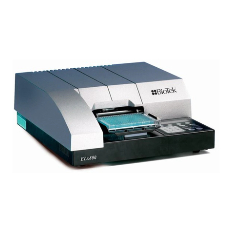
Bio-Tek
Bio-Tek ELx800 User manual

Bio-Tek
Bio-Tek MultiFlo FX User manual
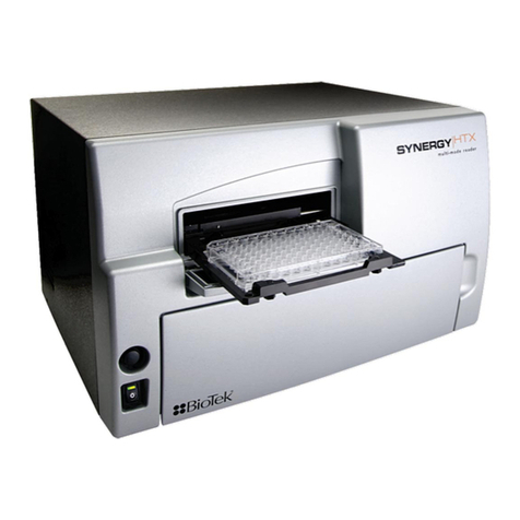
Bio-Tek
Bio-Tek Synergy HTX User manual
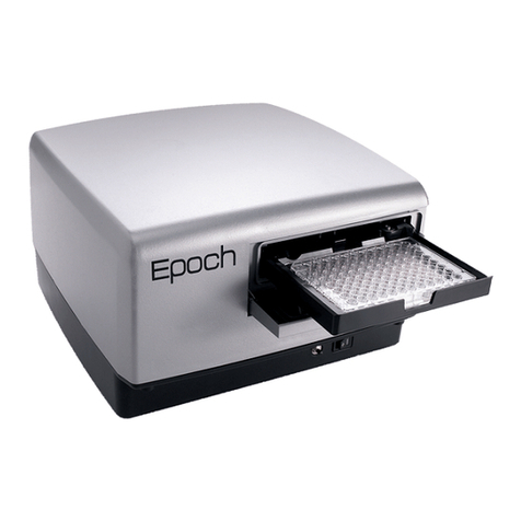
Bio-Tek
Bio-Tek Epoch User manual
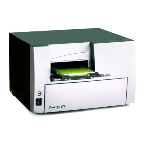
Bio-Tek
Bio-Tek Synergy HT User manual

Bio-Tek
Bio-Tek Synergy HTX User manual

Bio-Tek
Bio-Tek Synergy HT User manual
Bio-Tek
Bio-Tek 800TSI User manual
Bio-Tek
Bio-Tek Synergy LX User manual
Bio-Tek
Bio-Tek OM-1000 User manual
