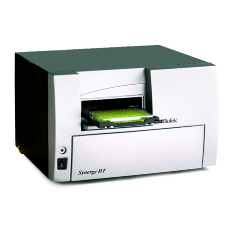
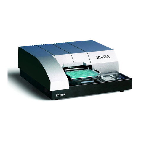
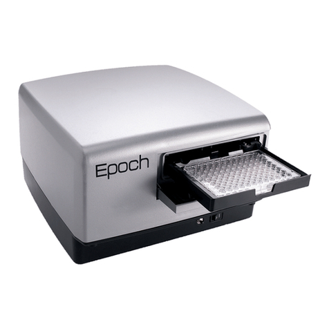
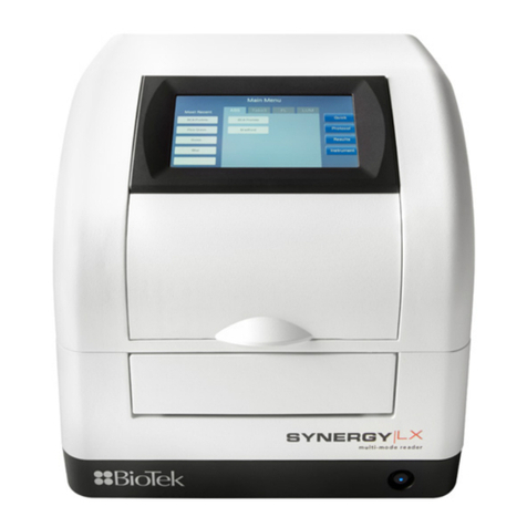
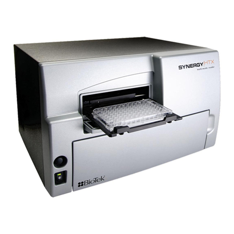
Bio-Tek Synergy HTX User manual

Operator’s Manual
Multi-Mode Microplate Reader
Synergy™ HTX

Contents | iii
Contents
Contact Information ........................................................... v
Customer Service and Sales............................................ v
Global Service and Support............................................. v
Document Conventions......................................................vii
Revision History .............................................................. viii
Intended Use Statement .....................................................ix
Quality Control ..................................................................ix
Warranty and Product Registration .......................................ix
Repackaging and Shipping .................................................. x
Warnings.......................................................................... x
Hazards............................................................................ x
Precautions......................................................................xii
CE Mark ......................................................................... xiii
Directive 2004/108/EC: Electromagnetic Compatibility ..... xiii
Directive 2006/95/EC Low Voltage (Safety)..................... xiii
Directive 2002/96/EC: Waste Electrical and Electronic
Equipment ................................................................. xiv
Directive 98/79/EC: In Vitro Diagnostics (if labeled for this
use) .......................................................................... xiv
Electromagnetic Interference and Susceptibility ................... xiv
USA FCC CLASS A ....................................................... xiv
Canadian Department of Communications Class A............ xiv
User Safety......................................................................xv
Safety Symbols ............................................................... xvi
Introduction .........................................................................1
Synergy HTX Multi-Mode Microplate Reader ........................... 2
Package Contents .............................................................. 3
Optional Accessories .......................................................... 4
Product Support & Service .................................................. 5
Technical Assistance Center (TAC) ................................... 5
Returning Instruments for Service/Repair ......................... 5
Applications Support ...................................................... 5
Installation...........................................................................7
Product Registration........................................................... 8
1: Unpack and Inspect the Reader ....................................... 8
2: Remove the Shipping Panel ........................................... 10
3: Remove the Microplate Carrier Shipping Screw................. 11
4: Install the Fluorescence Lamp Assembly.......................... 12
Synergy HTX Operator’s Manual

iv | Preface
5: Select an Appropriate Location....................................... 13
6: Connect the Power Supply............................................. 14
7: Unpack and Inspect the Dispense Module ........................ 15
8: Install the Dispense Module........................................... 18
Record Syringe Calibration Values.................................. 18
Install the Dispenser.................................................... 18
9: Connect the Host Computer .......................................... 20
10: Install Gen5 Software ................................................. 20
11: Turn on the Reader .................................................... 20
12: Establish Communication ............................................ 21
13: Set the Dispenser Calibration Values............................. 22
14: Run a System Test ..................................................... 23
15: Test the Injector System............................................. 24
Operational/Performance Qualification ................................ 26
Repackaging and Shipping Instructions ............................... 26
Getting Started................................................................... 31
Key Components ............................................................. 32
Power Switch, Carrier Eject Button, Microplate Carrier ...... 32
Lamp Assembly and Filter Wheel Access ......................... 33
Excitation and Emission Filter Wheels ............................. 34
Installing the Time-Resolved Fluorescence Cartridge ........ 37
Configuring the System for Luminescence Measurements.. 38
The External Dispense Module....................................... 39
Gen5 Software ................................................................ 41
Viewing/Updating the Filter and Wavelengths Tables ........ 42
Creating Protocols and Experiments ............................... 43
Controlling the Dispense Module .................................... 45
Recommendations for Optimum Performance....................... 48
Incubation and Partial Plates......................................... 49
Preventive Maintenance ..................................................... 51
Recommended Maintenance Schedule................................. 52
Overview ................................................................... 52
Daily Cleaning for the Dispense Module .......................... 52
Recommended Maintenance Schedule ............................ 53
Warnings and Precautions ................................................. 54
Cleaning Exposed Surfaces................................................ 55
Inspect/Clean Excitation and Emission Filters....................... 56
Flush/Purge the Fluid Path ................................................ 57
Running a Dispense Protocol (Optional) .............................. 58
Empty/Clean the Tip Priming Trough .................................. 59
Clean the Priming Plate..................................................... 59
Clean the Internal Components.......................................... 60
BioTek Instruments, Inc.

Contents | v
Required Materials....................................................... 61
Removing the Reader’s Shroud...................................... 62
Removing the Internal Tubes and Injector Heads ............. 64
Cleaning the Internal Tubes and Injector Heads............... 67
Cleaning the Optical Probes .......................................... 68
Cleaning the Reader’s Internal Surface ........................... 76
Reassembling the Components...................................... 77
Performance Check...................................................... 79
As-Needed Maintenance ..................................................... 81
Purpose.......................................................................... 82
Required Materials ........................................................... 83
Procedure for Models without Injectors ............................... 84
Routine Procedure for Models with Injectors ........................ 85
Clean Exposed Surfaces ............................................... 85
Decontaminate the Fluid Lines....................................... 86
Rinse the Fluid Lines .................................................... 87
Clean the Internal Tubing and Injector Heads.................. 87
Clean the Tip Priming Trough and Priming Plate ............... 88
Alternate Procedure for Models with Injectors ...................... 89
Instrument Qualification ....................................................91
Overview ........................................................................ 92
IQ/OQ/PQ....................................................................... 92
Recommended Qualification Schedule ................................. 94
System Test.................................................................... 95
Absorbance Plate Test .....................................................100
Test Plate Certificates .................................................100
Define Absorbance Test Plate Parameters ......................100
Run the Absorbance Plate Test .....................................101
Results and Troubleshooting Tips..................................104
Luminescence Tests ........................................................105
Harta Plate Test .........................................................106
Gen5 Protocol Reading Parameters ...............................107
Troubleshooting .........................................................109
Absorbance Liquid Tests ..................................................109
Absorbance Liquid Test 1.............................................110
Absorbance Liquid Test 2.............................................112
Absorbance Liquid Test 3 (optional) ..............................114
Fluorescence Tests..........................................................116
Required Materials......................................................117
Test Solutions............................................................118
Procedure .................................................................119
Results Analysis .........................................................119
Synergy HTX Operator’s Manual

vi | Preface
Troubleshooting .........................................................120
Pipette Map ...............................................................121
Gen5 Protocol Reading Parameters ...............................122
Fluorescence Tests Using Methylumbelliferone................126
Dispense Module Tests ....................................................131
Required Materials......................................................132
Alternate Test Solutions ..............................................133
Procedure for Models with Absorbance Capabilities..........133
Procedure for Models without Absorbance Capabilities .....135
Results Analysis .........................................................136
Gen5 Test Protocols for Models with Absorbance Capabilities137
Gen5 Test Protocols for Models without Absorbance
Capabilities ...............................................................139
Create the Dispense Protocols ......................................139
Specifications ................................................................... 143
General Specifications .....................................................144
Absorbance Specifications ................................................145
Fluorescence Specifications ..............................................147
Luminescence Specifications.............................................148
Models with Injectors ......................................................149
Error Codes ...................................................................... 151
Error Codes Overview......................................................152
Contact Info: BioTek Service/TAC .................................152
Error Codes ...................................................................153
BioTek Instruments, Inc.

Chapter 1
Introduction
This chapter introduces the Synergy HTX, describes its key
features, lists its package contents, and provides contact
information for technical assistance.
Synergy HTX Multi-Mode Microplate Reader ............................... 2
Package Contents................................................................... 3
Optional Accessories ............................................................... 4
Product Support & Service ....................................................... 5
Technical Assistance Center (TAC)........................................ 5
Returning Instruments for Service/Repair.............................. 5
Applications Support .......................................................... 5

2| Chapter 1: Introduction
Synergy HTX Multi-Mode Microplate Reader
The Synergy HTX is a single-channel microplate reader available with absorbance,
fluorescence, and luminescence detection. It is computer-controlled using BioTek’s Gen5
software for all operations including data reduction and analysis. Synergy HTX is robot
accessible and compatible with BioTek’s BioStack Microplate Stacker.
When making fluorescence determinations, the Synergy HTX uses a tungsten quartz
halogen lamp with interference filters for wavelength specificity in conjunction with a
photomultiplier (PMT) tube detector. The Synergy HTX has both top and bottom probes
for fluorescence measurements. The top probe can be adjusted vertically for the correct
reading height, via Gen5’s Read Height reading parameter (see Chapter 3, Getting
Started).
Luminescence is measured by the low-noise PMT detector through an empty filter position
in the Emission filter wheel. A filter can also be left in place if light filtering is necessary.
Absorbance measurements are made by switching to a xenon flash lamp and a
monochromator for wavelength selection. The use of a xenon flash lamp allows for both
UV and visible light absorbance measurements. The monochromator provides wavelength
selection from 200 to 999 nm in 1-nm increments.
The Synergy HTX has a 4-Zone temperature control from 4°C over ambient to 50°C,
controlled via a software-adjustable gradient. Internal plate shaking, with both linear and
orbital modes, is supported to ensure that reagents are properly mixed prior to reading.
Both Synergy HTX models support the reading of 6-, 12-, 24-, 48-, 96-, and 384-well
microplates with standard 128 x 86 mm geometry, as well as the BioTek Take3 and Take3
Trio Micro-Volume Plates. Absorbance mode reads plates up to 0.8" (20.3 mm) in height;
fluorescence mode reads plates up to 1.25" (31.75 mm). Polymerase Chain Reaction (PCR)
tubes up to 1.25" (31.75 mm) are also readable with the use of existing adapter plates.
For models with time-resolved fluorescence (TRF) capability, the TRF option allows
measurements by using the xenon flash light source in conjunction with the PMT
measurement detector. A special cartridge installed in the Excitation filter wheel location is
required.
Models with injectors support dual-reagent dispensing to 6-, 12-, 24-, 48-, 96-, and 384-well
microplates with standard 128 x 86 mm geometry. An external dispense module pumps
fluid from the supply bottles to the two injectors located inside the instrument. Both
injectors are positioned directly above the bottom probe, and fluid is injected into one well
at a time.
BioTek Instruments, Inc.

Package Contents | 3
Package Contents
Part numbers and package contents are subject to change. Contact
BioTek Customer Care with any questions.
Item
Part #
Synergy HTX Operator’s Manual 1341000
Power supply 76061
Power cord set (specific to installation environment):
Europe (Schuko)
USA/International
United Kingdom
Australia/New Zealand
75010
75011
75012
75013
RS-232 serial cable 75034
USB cable
with USB Driver Software
75108
7090204
Wrench 7772028
Fluorescence lamp assembly*(Note: The replacement lamp assembly is
PN 7080500)
7080501
Filter “plugs” (2) (also referred to as “dummy filters” or “blanks”)*7082073
Plastic storage bag and fastener strips —
Time-Resolved Fluorescence cartridge assembly (“T” models only) 7090523
Models with injectors, an external dispense module (packed
separately), with the following accessories:
Outlet tubes (2, plus 2 spare) from dispense module to instrument
Inlet tubes (2) from supply bottles to syringe drives
250 µl syringes (2)
Syringe thumbscrews (2)
Priming plate
Injector tip priming trough
Dispense module communication cable
Dispense module front cover
Supply bottles (2, 30 mL)
Supply bottle holder assemblies (2)
Injector tip cleaning stylus and plastic storage bag
7082120
7082121
7083000
19511
7132158
1342017
75107
7082137
7122609
7090564
2872304
* If applicable to your reader model.
Synergy HTX Operator’s Manual

4| Chapter 1: Introduction
Optional Accessories
Accessory availability and part numbers are subject to change. Contact
BioTek Customer Care with questions or visit www.biotek.com and use
the Accessories search tool.
Item
Part #
7-filter Absorbance Test Plate 7260522
Fluorescence Test Plate 7092092
Product Qualification (IQ-OQ-PQ) package 1340508
PCR Tube Adapter Plates 6002072 and
6002076
Terasaki Adapter Plate 7330531
Take3 Micro-Volume Plate TAKE3
Take3 Trio Micro-Volume Plate Take3Trio
BioCell Quartz Vessel and Adapter Plate 7272051/7270512
Additional Fluorescence Filters; contact BioTek for part numbers and availability
The Synergy HTX is compatible with the BioStack Microplate Stacker. Contact BioTek or
visit our website to learn more.
For Use with Liquid Tests (see Chapter 5) Part #
Absorbance Liquid Test Solutions:
BioTek Wetting Agent Solution
BioTek QC Check Solution #1
25 mL
125 mL
7773002
7120779
7120782
Dispense Module Liquid Test Solution:
BioTek Green Test Dye
BioTek Blue Test Dye
BioTek QC (Yellow) Test Dye
7773003
7773001
7120782
Individual Fluorescence Liquid Test Solutions:
Sodium Fluorescein Powder
Liquid Test Kit using Sodium Fluorescein
Liquid Test Kit using Methylumbelliferone (“MUB”)
98155
7160013
7160012
BioTek Instruments, Inc.

Product Support & Service | 5
Product Support & Service
Technical Assistance Center (TAC)
If your instrument(s) or software fails to function properly, if you have questions about
how to use or maintain our products, or if you need to send an instrument to BioTek
for service or repair, please contact our Technical Assistance Center. BioTek’s “TAC” is
open from 8:30 AM to 5:30 PM (EST), Monday through Friday, excluding standard U.S.
holidays. You can send a fax or an e-mail any time. You can also request technical
assistance via our website: www.biotek.com.
(802) 655-4740 Web: www.biotek.com
Please be prepared to provide the following information:
•Your name and company information, along with a daytime phone or fax
number, and/or an e-mail address
•The product name, model, and serial number
•The onboard software part number and version (available through Gen5 at
System > Instrument Configuration > Get Basecode Information)
•Gen5 software version information (Help > About Gen5)
•For troubleshooting assistance or instruments needing repair, the specific steps
that produce your problem and any error codes displayed in Gen5
(see also Appendix C, Error Codes)
•A text file of the diagnostic history of the instrument (available via Gen5 by
selecting System > Diagnostics > History, then selecting the appropriate
file and clicking Export)
Returning Instruments for Service/Repair
If you need to return an instrument to BioTek for service or repair, please contact the
TAC for a service authorization number before shipping the instrument. Repackage the
instrument properly (see Chapter 2, Installation), write the number on the shipping
box, and ship to BioTek.
Applications Support
BioTek’s fully equipped Application Laboratory provides our on-staff scientists with
the means to assist you with the integration of our instrumentation and software with
your unique scientific applications. If you are having difficulty with optimizing
fluorescence sensitivity or integrating a unique data reduction transformation, or you
are just looking for a recommendation on an appropriate fluorophore, contact us.
Synergy HTX Operator’s Manual

Chapter 3
Getting Started
This chapter describes some of the Synergy HTX’s key components
and provides an introduction to using Gen5 to control the
instrument.
Key Components .................................................................. 32
Power Switch, Carrier Eject Button, Microplate Carrier........... 32
Lamp Assembly and Filter Wheel Access.............................. 33
Excitation and Emission Filter Wheels ................................. 34
Installing the Time-Resolved Fluorescence Cartridge ............. 37
Configuring the System for Luminescence Measurements ...... 38
The External Dispense Module ........................................... 39
Gen5 Software..................................................................... 41
Viewing/Updating the Filter and Wavelengths Tables............. 42
Creating Protocols and Experiments.................................... 43
Controlling the Dispense Module ........................................ 45
Recommendations for Optimum Performance ........................... 48
Incubation and Partial Plates ............................................. 49

32 | Chapter 3: Getting Started
Key Components
Power Switch, Carrier Eject Button, Microplate Carrier
Figure 12: Power switch, carrier eject button, microplate carrier
•The power switch contains an LED, which is illuminated green when the power is
on.
•The microplate carrier eject button can be used to move the microplate carrier into
or out of the measurement chamber and also to stop the instrument from
“beeping” when it encounters an error.
•The microplate carrier supports microplates and adapter plates as described in
Appendix A, Specifications. The plate is positioned so that well A1 is in the left
rear corner of the carrier. A spring clip holds the plate securely in place. The
microplate loading door helps to ensure a light-impermeable measurement
chamber. When a plate read is initiated, the carrier slides into the measurement
chamber and then moves on the X and Y axes to align each microwell with the top
or bottom fluorescence probe, or bottom absorbance probe, as specified in the Gen5
procedure. When the read is complete, the plate carrier slides to its full-out
position.
carrier eject button
power switch
microplate carrier
access door
filter wheel and
lamp access door
BioTek Instruments, Inc.

Key Components | 33
For fluorescence and luminescence reading modes, the height of the
top optical probe can be adjusted. Use the Read Height option to
define how far the top probe shall be offset from the top surface of the
plate during the read. In Gen5, this option is found in a Read step
within a Procedure. Refer to the Gen5 Help for further instructions.
Lamp Assembly and Filter Wheel Access
Applies only to Synergy HTX models with fluorescence and luminescence capability.
Figure 13: Accessing the fluorescence lamp assembly and filter wheels
•The fluorescence lamp assembly and the excitation and emission filter wheels are
accessible via a hinged door on the front of the instrument. To open the door, slip
your finger into the notch on the right side and pull the door downward. A
diagram showing the location of the lamp assembly and the orientation of the
excitation and emission filter wheels is printed on the inside of the hinged door.
•For models with the Time-Resolved Fluorescence feature, remove the excitation
filter wheel and replace it with the “TR” cartridge before running a time-resolved
fluorescence assay. See page 37 for more information on the TR cartridge.
Excitation
filter wheel (TRF
cartridge, when used)
Emission
filter wheel
Fluorescence
lamp assembly
Synergy HTX Operator's Manual
34 | Chapter 3: Getting Started
The Synergy HTX has two lamps: one for standard fluorescence, one
for absorbance and time-resolved fluorescence:
Standard Fluorescence: The 20-watt tungsten halogen lamp’s life is
rated at an average of 1000 hours, and it is user-replaceable. The
intensity of the bulb will slowly drop over time until the instrument’s
run-time self-check detects a low lamp current signal and Gen5
displays an error message. The lamp (PN 7080500) should be replaced
at this time. Keeping a spare lamp on hand is recommended.
Absorbance and Time-Resolved Fluorescence: This bulb should
outlive the useful life of the reader. If there is a problem with the
lamp, however, the intensity may drop and the run-time self-check will
detect a low signal level and generate an error message. If this
happens, the instrument will require service. Contact BioTek for
assistance (this lamp is not user-replaceable).
Excitation and Emission Filter Wheels
Synergy HTX models with fluorescence capability are equipped with one excitation
filter wheel and one emission filter wheel; readers with luminescence capability use an
emission filter wheel only. (A monochromator is used for absorbance measurements.)
A filter in the excitation wheel selects the narrow band of light to which the sample
will be exposed. A filter in the emission wheel selects the band of light with the
maximum fluorescence signal, to be measured by the photomultiplier (PMT).
Each filter wheel is labeled EX or EM, and can contain up to four filters and/or black
“plugs.” A filter can be used in either wheel, but it must be oriented properly, as
described below. Each filter and plug is held securely in place with a C-clip filter
retainer.
Each filter has its wavelength and bandpass values printed on its side,
with an arrow to indicate the proper direction of light through the
filter.
We recommend placing filters in the wheels in ascending wavelength
order from position 1 to 4 (no holes in EX2 or EM3), particularly if the
reader has generated a 4E18 (saturation) error.
BioTek Instruments, Inc.

Key Components | 35
Figure 14: Profiles of the excitation and emission filter wheels, showing proper filter orientation
Important! The Synergy HTX is shipped with a set of excitation
and emission filters installed, and the Synergy HTX’s onboard
software is preconfigured with the filter values and their
locations.
If you change the contents of a filter wheel, you must update
Gen5’s filter table and then download the information to the
reader. The Synergy HTX does not automatically detect which
filters are installed.
See page 42 for information on updating Gen5’s filter table.
Removing the Filter Wheels
The filter wheels can be removed if different filter wheels need to be installed.
It is important to note that:
485/20
Support
ing metal
bracket
Thumbscrew
EXCITATION
Filter wheel
Direction
of light
528/20
Note the difference in filter orientation between the
excitation and emission filter wheels
Direction
of light
EMISSION
Filter wheel
Synergy HTX Operator's Manual
36 | Chapter 3: Getting Started
•The excitation and emission filter wheels are not interchangeable
and are labeled as follows: EX = Excitation, EM = Emission.
(TR = Time-Resolved Cartridge; see page 37.)
•Filter direction within a filter wheel is important, and the direction differs
depending on the filter wheel. There is a diagram on the inside of the front
panel door indicating this.
•Each filter is marked with an arrow indicating the proper direction of light.
Refer to the figures on the previous page for proper filter orientation.
To remove a filter wheel:
1. Important! Turn off the instrument.
2. Open the filter wheel access door using the depression on the right side of
the door.
3. Observe the two thumbscrews within the compartment. The left
thumbscrew holds the excitation filter wheel in place; the right secures the
emission filter wheel.
4. Remove the thumbscrew and slide the filter wheel’s supporting metal
bracket straight out of the compartment. Note: The emission filter wheel
will “spring” out when removed. (This is because a shutter behind the
wheel closes quickly to protect the PMT.)
Important! When removing or replacing a filter or C-clip
filter retainer, do not use a sharp instrument! Use several
layers of lens paper and your finger to remove and replace
filters and clips. Using a sharp instrument, such as a flat
screwdriver, will scratch the filter surface and make it
unusable.
Do not touch the filters with your bare fingers!
To remove a filter or plug:
1. Turn the filter wheel to align the desired filter with the hole in the
supporting bracket.
2. Place the bracket on a flat surface, with the filter wheel facing down.
3. Prepare a multi-layered “cushion” of lens paper. Using your finger covered
with the lens paper, gently push against the filter and its C-clip retainer
until they pop out.
To replace a filter or plug:
1. Hold the metal bracket with the filter wheel facing up.
BioTek Instruments, Inc.

Key Components | 37
2. Properly orient the filter or plug (see page 34), and then drop it into the
desired filter wheel location.
3. Using your fingers, squeeze the sides of the C-clip filter retainer, and then
insert it into the top of the hole containing the new filter. Cover your finger
with several layers of lens paper, and then push down on all sides of the C-
clip until it sits flush against the filter.
4. Clean both sides of the filter with lens paper.
To reinstall a filter wheel:
1. Ensure that all filters and/or plugs are inserted properly (see above).
2. Slide the filter wheel back into its chamber.
3. Replace the thumbscrew.
4. Close the front door.
5. Turn on the instrument.
Installing the Time-Resolved Fluorescence Cartridge
For Synergy HTX models that support time-resolved fluorescence, the “TR” cartridge
must be installed in place of the excitation filter wheel before a TRF assay can be run.
The TR cartridge allows light from the xenon flash bulb to be input to the fluorescence
optical system within the Synergy HTX. Excitation wavelengths are selected by
adjusting the monochromator from 200 to 999 nm in 1-nm increments, with a fixed
bandwidth of 10 nm.
The Synergy HTX automatically detects the presence of the TR
cartridge. At the start of a time-resolved fluorescence assay, the
operator will be prompted to install the TR cartridge if it is missing.
1. Important! Turn off the instrument.
2. Open the filter wheel access door using the depression on the right side of
the door. Observe the two thumbscrews within the compartment. The left
thumbscrew holds the Excitation filter wheel in place. See the figure on
page 33.
3. Remove the left thumbscrew and slide the filter wheel’s supporting metal
bracket straight out of the compartment.
4. Slide the TR cartridge into the compartment and replace the thumbscrew.
Close the front door and turn on the instrument.
See page 43 for more information on creating Gen5 protocols.
Synergy HTX Operator's Manual
38 | Chapter 3: Getting Started
Figure 15: The “TR” cartridge, for time-resolved fluorescence assays
Configuring the System for Luminescence Measurements
•For best results when taking luminescence measurements, the excitation filter
wheel should have no empty locations, and it should have at least one “plug” (also
referred to as a “dummy filter”) installed to prevent light from reaching the
samples. Remove the excitation filter wheel (see page 35) and examine its contents;
ensure that there are no empty locations and there is at least one plug installed.
•If your tests require that the light emitted from the samples remain unfiltered, the
emission filter wheel should have an empty location in it. Remove the emission
filter wheel and examine its contents; ensure that there is an empty location.
•If you made any changes to either filter wheel, you must update Gen5’s filter table.
Select “PLUG” to indicate the presence of a plug and “HOLE” to indicate an empty
location. Click Send Values to download the information to the reader.
Updating Gen5’s filter table; for complete instructions, see page 42.
BioTek Instruments, Inc.

Key Components | 39
•When defining a filter set in a Read
step in a Gen5 procedure, selecting
“Hole” indicates the empty location in
the emission filter wheel. See page 43
for information on Read steps and
procedures.
The External Dispense Module
Applies only to Synergy HTX models with injectors.
The dispense module pumps fluid from the supply bottles to injector heads located
inside the instrument. Fluid is injected into one well at a time.
Figure 16: Dispense module components
•Two 250-µL syringes draw fluid from the supply bottles.
•Inlet tubes transport fluid from the supply vessels to the syringes. These tubes
are short pieces of opaque PTFE (Teflon) tubing connected to stainless-steel
probes on one end and threaded fittings on the other end.
Synergy HTX Operator's Manual
40 | Chapter 3: Getting Started
•Three-way valves switch the syringe flow from the inlet tubes to the outlet
tubes.
•Outlet tubes transport fluid from the syringes into the instrument, through the
tubing ports on the Synergy HTX’s rear panel. The outlet tubes are opaque
PTFE tubes with threaded fittings on each end that are used to deliver fluid
from the syringes to the instrument.
Inside the Synergy HTX, two Teflon tubes transport fluid from the tubing ports on
the rear of the instrument to the two injectors. As shown below, both injectors are
positioned directly above the bottom fluorescence optical probe.
Syringe 1 Syringe 2
Bottom probe
Figure 17: Close-up view of the injectors inside the instrument
The tubing and injectors should be cleaned at least quarterly. See
Chapter 4, Preventive Maintenance for more information.
BioTek Instruments, Inc.
Other manuals for Synergy HTX
1
Table of contents
Other Bio-Tek Laboratory Equipment manuals

Bio-Tek
Bio-Tek ELx800 User manual
Bio-Tek
Bio-Tek ELx800 User manual

Bio-Tek
Bio-Tek Epoch User manual
Bio-Tek
Bio-Tek Synergy H1 User manual
Bio-Tek
Bio-Tek Synergy HTX User manual

Bio-Tek
Bio-Tek ELx808 User manual

Bio-Tek
Bio-Tek MultiFlo FX User manual

Bio-Tek
Bio-Tek Synergy HT User manual

Bio-Tek
Bio-Tek Synergy LX User manual

Bio-Tek
Bio-Tek Synergy H1 User manual