Bittium NeurOne User manual
Page 1 of 191
800581-2.11 NeurOne System User Manual.doc
NeurOne User Manual
Date of issue: February 21st 2018

Page 2 of 191
800581-2.11 NeurOne System User Manual.doc
Table of Contents
1INTRODUCTION....................................................................................................................................................... 8
1.1 USING THIS MANUAL ................................................................................................................................................... 8
1.2 SYMBOLS USED WITH THE DEVICE ................................................................................................................................... 9
1.3 USER RESPONSIBILITY ................................................................................................................................................... 9
1.4 WARRANTY .............................................................................................................................................................. 10
2GENERAL HANDLING ............................................................................................................................................. 11
2.1 PRODUCT OVERVIEW.................................................................................................................................................. 11
2.2 SYSTEM DIAGRAMS .................................................................................................................................................... 12
2.3 SYSTEM FUNCTIONS ................................................................................................................................................... 14
2.4 USABILITY................................................................................................................................................................. 14
2.5 MAINTENANCE AND SERVICE........................................................................................................................................ 15
2.5.1 Cleaning ........................................................................................................................................................ 15
2.5.2 Calibration..................................................................................................................................................... 15
2.6 DISPOSAL AND ENVIRONMENTAL ISSUES......................................................................................................................... 15
3SOFTWARE INSTALLATION .................................................................................................................................... 16
3.1 SYSTEM REQUIREMENTS FOR THE COMPUTER.................................................................................................................. 16
3.2 VIDEO CAMERA REQUIREMENTS FOR NEURONE VIDEO OPTION ......................................................................................... 16
3.3 INSTALLING THE NEURONE PC SOFTWARE...................................................................................................................... 17
3.3.1 SQL Server 2014 Installation ......................................................................................................................... 17
3.3.2 Visual C++ 2015 Redistributable Installation ................................................................................................ 22
3.3.3 NeurOne software Installation...................................................................................................................... 23
3.3.4 NeurOne Database Conversion ..................................................................................................................... 26
3.4 INSTALLING NEURONE VIDEO OPTION ........................................................................................................................... 29
3.5 CONFIGURING THE ETHERNET ADDRESS FOR THE COMPUTER.............................................................................................. 29
3.5.1 NeurOne IP address....................................................................................................................................... 30
4HARDWARE INSTALLATION................................................................................................................................... 31
4.1 MAIN UNIT –MODEL EXTENDED .................................................................................................................................. 32
4.2 MAIN UNIT –MODEL BLACK ......................................................................................................................................... 33
4.3 MAIN UNIT –MODEL BLACK HIGH................................................................................................................................. 34
4.4 EXG AMPLIFIER......................................................................................................................................................... 36
4.5 TESLA AMPLIFIER ....................................................................................................................................................... 37
4.6 JACKBOX.................................................................................................................................................................. 38
4.7 BIPOLAR CONNECTION BOX ......................................................................................................................................... 39
4.8 VIDEO OPTION .......................................................................................................................................................... 40
4.9 GETTING NEURONE SYSTEM OPERATIONAL..................................................................................................................... 41
4.9.1 Operations controlled by the Power button of Main Unit............................................................................. 43
4.9.1.1 Switching off NeurOne System ................................................................................................................................... 44
4.10 MANUAL ACTIVATION OF CALIBRATION FILES AND FW VERSION CHECK ................................................................................. 44
4.11 CONNECTING SENSORS ............................................................................................................................................... 45
4.12 CONNECTING EXTERNAL DEVICES.................................................................................................................................. 45
4.12.1 Isolated Trigger In/Out: Trigger A / Trigger B ............................................................................................... 45
4.12.2 Non-Isolated 8-bit Trigger in ......................................................................................................................... 45
4.12.3 Analog Output............................................................................................................................................... 46
4.12.4 Digital OUT.................................................................................................................................................... 46
4.12.4.1 Specification ........................................................................................................................................................... 46
4.12.4.2 Features.................................................................................................................................................................. 46
4.13 AC ADAPTERS ........................................................................................................................................................... 47
4.14 BATTERY PACK USE .................................................................................................................................................... 47

Page 3 of 191
800581-2.11 NeurOne System User Manual.doc
4.14.1 New Battery Packs with battery type and low battery state detection ........................................................ 47
4.14.2 Battery Pack 12 V for EXG amplifier.............................................................................................................. 48
4.14.3 Battery Pack 6 V for Tesla amplifier.............................................................................................................. 48
4.14.4 Battery Pack 7.2 V for Tesla amplifier........................................................................................................... 49
4.14.5 Charging the Battery Pack ............................................................................................................................ 49
4.14.5.1 Battery Pack 12V of EXG amplifier.......................................................................................................................... 49
4.14.5.2 Battery Pack 6V of Tesla amplifier.......................................................................................................................... 50
4.14.5.3 Battery Pack 7.2V of Tesla amplifier....................................................................................................................... 50
4.14.6 Connecting the Battery Pack......................................................................................................................... 51
4.15 SPECIAL CONFIGURATIONS USING SYNCBOX .................................................................................................................... 52
5USING THE SOFTWARE.......................................................................................................................................... 55
5.1 PERSON DETAILS........................................................................................................................................................ 55
5.2 PROJECTS ................................................................................................................................................................. 57
5.3 PROTOCOL -MEASUREMENT PROTOCOL ........................................................................................................................ 58
5.3.1 Front Page of the Protocol Tool .................................................................................................................... 58
5.3.2 Main Properties - Protocol subtab ................................................................................................................ 59
5.3.3 Signal Inputs.................................................................................................................................................. 59
5.3.4 Real-time Out................................................................................................................................................ 62
5.3.4.1 Digital OUT settings .................................................................................................................................................... 64
5.3.5 Montage ....................................................................................................................................................... 67
5.3.6 Plug-Ins ......................................................................................................................................................... 69
5.3.6.1 Audio Output Control ................................................................................................................................................. 69
5.3.6.2 Data Writer ................................................................................................................................................................. 70
5.3.6.3 Impedance .................................................................................................................................................................. 70
5.3.6.4 Raw Signal Monitor..................................................................................................................................................... 71
5.3.6.5 Response Monitor....................................................................................................................................................... 72
5.3.6.6 Video Monitor............................................................................................................................................................. 75
5.3.7 Finalizing the Protocol................................................................................................................................... 75
5.4 MEASUREMENT......................................................................................................................................................... 76
5.4.1 Monitors........................................................................................................................................................ 78
5.4.1.1 Raw Monitor Properties ............................................................................................................................................. 79
5.4.1.2 Response Monitor Properties ..................................................................................................................................... 82
5.4.2 Impedance Test ............................................................................................................................................. 86
5.4.3 Audio output control ..................................................................................................................................... 90
5.4.4 EEG recording –entering comments............................................................................................................. 90
5.4.5 EP recording .................................................................................................................................................. 92
5.4.6 Video recording............................................................................................................................................. 93
5.5 VIEWING THE RESULTS ................................................................................................................................................ 94
5.5.1 Review window ............................................................................................................................................. 97
5.5.2 Viewing data with video ............................................................................................................................. 104
5.6 RECORDED RESPONSES.............................................................................................................................................. 105
5.7 TOOLS FOR UNIVERSAL INPUT GROUPS,MONTAGES AND DISPLAY FILTERS ............................................................................ 106
5.7.1 Input Group pool ......................................................................................................................................... 106
5.7.2 Montage pool.............................................................................................................................................. 108
5.7.3 Display filter pool ........................................................................................................................................ 110
5.8 ACCESSING SETTINGS ................................................................................................................................................ 113
5.8.1 Core - System settings................................................................................................................................. 114
5.8.1.1 NeurOne manager .................................................................................................................................................... 117
5.8.2 Remote Control ........................................................................................................................................... 121
5.8.2.1 Remote control settings............................................................................................................................................ 121
5.8.3 Appearance –user preferences................................................................................................................... 123
5.8.4 License settings ........................................................................................................................................... 123
5.8.5 Institute settings ......................................................................................................................................... 124
5.9 CALIBRATION .......................................................................................................................................................... 125
5.9.1 Calibration adapters ................................................................................................................................... 125
5.9.2 Recommended calibration method............................................................................................................. 125

Page 4 of 191
800581-2.11 NeurOne System User Manual.doc
5.10 GETTING HELP ......................................................................................................................................................... 131
6EXAMPLE CASE: P300 .......................................................................................................................................... 132
7TROUBLESHOOTING............................................................................................................................................ 137
8SPECIFICATIONS .................................................................................................................................................. 138
8.1 MAIN UNIT (MODEL EXTENDED) ................................................................................................................................. 138
8.2 MAIN UNIT (MODEL BLACK)....................................................................................................................................... 138
8.3 MAIN UNIT (MODEL BLACK HIGH)............................................................................................................................... 139
8.4 EXG AMPLIFIER....................................................................................................................................................... 140
8.5 TESLA AMPLIFIER ..................................................................................................................................................... 141
8.6 JACKBOX................................................................................................................................................................ 142
8.7 SYNCBOX ............................................................................................................................................................... 142
8.8 BATTERY PACK 6V ................................................................................................................................................... 143
8.9 BATTERY PACK 7.2V ................................................................................................................................................ 143
9REGULATIONS AND DECLARATIONS.................................................................................................................... 144
APPENDIX 1: PINOUTS OF TESLA AMPLIFIER KEL CONNECTORS ................................................................................. 147
APPENDIX 2: PINOUTS OF EXG AMPLIFIER D-CONNECTORS....................................................................................... 148
APPENDIX 3: PINOUT OF NON-ISOLATED 8-BIT TRIGGER ............................................................................................ 149
APPENDIX 4: PINOUT OF ANALOG OUTPUT ................................................................................................................ 150
APPENDIX 5: NEURONE DATA FORMAT ...................................................................................................................... 151
BINARY FILES ...................................................................................................................................................................... 151
SIGNAL FILES....................................................................................................................................................................... 151
EVENT FILES........................................................................................................................................................................ 152
PROTOCOL.XML................................................................................................................................................................... 154
SESSION.XML ...................................................................................................................................................................... 155
SYSTEMINFO.XML ................................................................................................................................................................ 155
HEADBOXVOLTAGES.XML...................................................................................................................................................... 156
APPENDIX 6: USE OF EXTERNAL SIGNALS.................................................................................................................... 157
APPENDIX 7: EEGLAB PLUG-IN .................................................................................................................................... 161
EEGLAB............................................................................................................................................................................ 161
INSTALLATION ..................................................................................................................................................................... 161
USAGE............................................................................................................................................................................... 161
USE RESTRICTIONS ............................................................................................................................................................... 161
APPENDIX 8: REMOTE CONTROL................................................................................................................................. 162
SUPPORTED COMMANDS....................................................................................................................................................... 162
COMMAND EXAMPLES .......................................................................................................................................................... 163
Command example 1: Start recording ........................................................................................................................ 163
Command example 2: Stop recording (with 2 clients) ................................................................................................ 164
Command example 3: Status query ............................................................................................................................ 164
Command example 4: Recording start fails ................................................................................................................ 164
APPENDIX 9: BIPOLAR CONNECTION BOX................................................................................................................... 165
CONFIGURATION –ADJUSTABLE DIP SWITCHES.......................................................................................................................... 165
ACCEPTED CONFIGURATIONS.................................................................................................................................................. 166
CONFIGURATION CHANGE /CHECK .......................................................................................................................................... 166
PRIOR TO NEW MEASUREMENT SESSION ................................................................................................................................... 169
APPENDIX 10: PINOUTS OF CONNECTORS ON BIPOLAR CONNECTION BOX ................................................................ 170

Page 5 of 191
800581-2.11 NeurOne System User Manual.doc
APPENDIX 11: DIGITAL OUT ........................................................................................................................................ 171
FEATURES........................................................................................................................................................................... 171
PACKET TYPES ..................................................................................................................................................................... 171
MEASUREMENTSTARTPACKET................................................................................................................................................ 172
SAMPLES PACKET................................................................................................................................................................. 173
SEND TRIGGERS AS A CHANNEL MODE..................................................................................................................................... 174
TRIGGER PACKETS................................................................................................................................................................ 175
MEASUREMENTEND PACKET.................................................................................................................................................. 176
HARDWARESTATE PACKET..................................................................................................................................................... 177
CLOCKSOURCESTATE PACKET ................................................................................................................................................. 177
JOIN PACKET....................................................................................................................................................................... 178
EXAMPLES .......................................................................................................................................................................... 179
GNU OCTAVE SCRIPT FOR RECEIVING UDP SAMPLE PACKETS: ...................................................................................................... 184
APPENDIX 12: RAW MONITOR CONTROL PARAMETERS ............................................................................................. 185
APPENDIX 13: RESPONSE MONITOR CONTROL PARAMETERS..................................................................................... 186
APPENDIX 14: MR CONDITIONAL STATEMENT OF COMPLIANCE FOR NEURONE TESLA AMPLIFIER, BATTERY PACK AND
ACCESSORIES .............................................................................................................................................................. 188
MRI INFORMATION ............................................................................................................................................................. 189
STATIC MAGNETIC FIELD ....................................................................................................................................................... 189
MRI RELATED RF HEATING .................................................................................................................................................... 190
FOR SAFE USE...................................................................................................................................................................... 190
FOR SAFE USE...................................................................................................................................................................... 191

Page 6 of 191
800581-2.11 NeurOne System User Manual.doc
Intended Use of NeurOne System
Electroencephalograph.
An electroencephalograph is a device used to measure and record the electrical activity of the
patient's brain obtained by placing two or more electrodes on the head.
Classification of NeurOne System
According to MDD 93/42/EEC and amended by Directive 2007/47/EC: Class IIa product
NeurOne equipment is designed according to and fulfils the requirements of following standards:
EN60601-1 (IEC60601-1) Medical electrical equipment. Part 1: General requirements for safety
EN60601-1-2 (IEC60601-1-2) Medical electrical equipment. General requirements for safety.
Electromagnetic compatibility - Requirements and safety
EN60601-2-26 (IEC60601-2-26) Medical electrical equipment. Particular requirements for the safety
of electroencephalographs.
The complete system, including personal computer, shall comply with EN6060-1-1 (IEC60601-1-1)
requirements.
NeurOne is according to EN60601-1 externally powered class 2 equipment.
Manufacturer Information
Bittium Biosignals Ltd. (Bittium Bisignals Oy)
Address: Pioneerinkatu 6, FI-70800 Kuopio, Finland
tel. +358 (0)17 581 7700
fax. +358 (0)17 580 0978
e-mail: bbs@bittium.com
web: www.bittium.com
Bittium Biosignals Ltd reserves all rights to improve, change and modify the products and the
contents of the User Manual without prior notice.
Page 7 of 191
800581-2.11 NeurOne System User Manual.doc
Connect only items that have been specified as part of the NeurOne System or that have been specified as
being compatible with the NeurOne System. The assembly of the NeurOne System and modifications
during the actual service life requires evaluations are the requirements of EN60601-1-1 standard still met.
To avoid danger of electrical shock and electromagnetic disturbances the computer and associated
equipment used with the NeurOne should comply with the following standards (or national variants):
EN 60950 Information technology equipment and office equipment safety.
EN 60601-1 Medical electrical equipment: General safety requirements.
EN 60601-1-2 Medical electrical equipment: Electromagnetic compatibility.
Connect only items that have been specified as part of the NeurOne System or that have been specified as
being compatible with the NeurOne System.
If a computer that does not comply with the EN 60601-1 requirements is used with the NeurOne in patient
environment, the computer and peripherals must be plugged in using an isolation transformer that fulfills the
requirements (see EN 60601-1-1 for detailed requirements).
Parts of non-medical equipment (PC computer and its accessories) and PATIENT shall not be touched
simultaneously by the OPERATOR.
This device is not to be used with patients, who have active implantable medical device (like heart
pacemaker etc.).
Conductive parts of ELECTRODES and their connectors, including the NEUTRAL ELECTRODE, should
not contact other conductive parts including earth.
This ELECTROENCEPHALOGRAPH is not intended to be used simultaneously with the cardiac defibrillator
or with high frequency (HF) surgical equipment.
For the NeurOne Main Unit use only the Power Supply supplied by Bittium Biosignals Ltd.
If MULTIPLE PORTABLE SOCKET-OUTLETS are used these shall only be used for supplying power to
equipment which is intended to form part of the SYSTEM to ensure that leakage currents do not exceed.
The MULTIPLE PORTABLE SOCKET-OUTLET shall meet EN 60601-1-1 requirements (see standard for
detailed requirements).
Ensure that the maximum permitted load for any MULTIPLE SOCKET-OUTLET(S) used with the NeurOne
System does not exceed with connected equipment.
Additional MULTIPLE SOCKET-OUTLET or extension cord shall not be connected to the NeurOne System.
Devices that produce electro-magnetic field, such as mobile phones, radio transmitters and electric motors
could cause distortions in measured data. Make sure that environment of the measurement is free from such
devices.
If a computer that does not comply with the EN 60601-1-2 requirements is used with the NeurOne, the
computer may cause EMC disturbance.
Ensure specially that all NeurOne cables are free from EMC disturbances.
Carry out all adjustment and cleaning PROCEDURES specified in instructions.

Page 8 of 191
800581-2.11 NeurOne System User Manual.doc
1
1
I
IN
NT
TR
RO
OD
DU
UC
CT
TI
IO
ON
N
1.1 Using This Manual
This manual has been written for the users of the NeurOne Biosignal Monitoring
Device. Users of the device should be acquainted with EEG measurements and
measurement setups before using the device.
In order to use the NeurOne System safely, all users must read this manual paying
attention to the warnings and cautions. Explanations for the various symbols can be
found in the following pages.
The manual is divided into three main parts: the first section focuses on the device and
its installation, while the second section addresses the software and its usage. The
final section contains device troubleshooting, declarations, regulatory and statutory
requirements and appendices.
Please note that some maintenance and service procedures specified in this manual,
require the use of special tools or devices. Some of these devices are available only
from Bittium Biosignals Ltd. Other devices are available on the market, but should
comply with the specification given in this manual. If not specified otherwise you may
also use common tools and devices.
IMPORTANT!
Before taking any action with the system parts, please read this manual thoroughly and
retain it for future reference.
Warning. These statements identify conditions or practices that could
result in personal injury or loss of life.
Caution. These statements identify conditions or practices that could
result in damage to the equipment or other property.
Note. These statements identify condition or practices that could result
in performance loss of the equipment or must be otherwise paid
attention to.
Page 9 of 191
800581-2.11 NeurOne System User Manual.doc
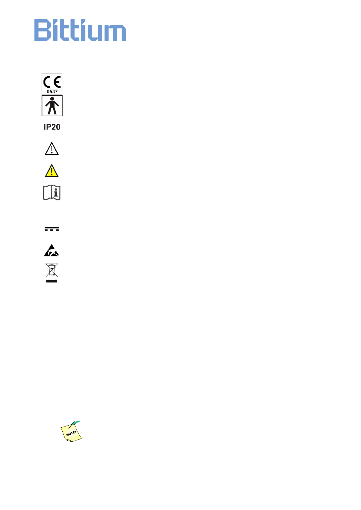
1.2 Symbols Used with the Device
The device is CE-marked for the conformity to Council Directive 93/42/EEC as amended by the
Directive 2007/47/EC regarding medical devices.
The device is equipped with type BF applied parts fulfilling the EN 60601-1 (IEC60601-1)
standard.
The enclosure protection class is IP20 according to EN60529.
Caution.
Warning.
Follow operating instructions.
~
Alternating current (A.C.)
Direct current (D.C.)
ESD sensitive connector.
For EU only: This symbol indicates that this device shall be disposed according to European
Union directive 2002/96/EC on Waste Electrical and Electronic Equipment (WEEE).
1.3 User Responsibility
This product shall be assembled, operated, maintained and repaired in accordance
with the instructions provided.
A defective product should not be used. Parts that are broken, worn, missing,
incomplete, distorted or contaminated should be replaced immediately. Should any
repair or replacement become necessary, we recommend that the device is delivered
to your local distributor or Bittium Biosignals Ltd for service.
The user of the product is solely responsible for any malfunction resulting from
improper use, faulty maintenance, improper repair, damage or alteration by anyone
other than Bittium Biosignals Ltd or their authorized service personnel.
NeurOne system does not provide any automatic analysis or
diagnosis.

Page 10 of 191
800581-2.11 NeurOne System User Manual.doc
1.4 Warranty
All repairs on products under warranty must be performed or approved by Bittium
Biosignals Ltd. Unauthorized repairs will void the warranty. The warranty terms are as
follows:
Warranty: 24 months unless otherwise specified herein below.
Coverage: Parts and labor unless otherwise specified herein below.
All warranties will be invalidated if unauthorized repairs are made to any parts of the
overall system.
The liability of Bittium Biosignals Ltd is limited to the repair of the product under
warranty and specifically excludes consequential loss. The warranty covers all labour
and parts associated with normal use. The warranty does not cover travelling expenses
in case the repair is needed at end-user’s facilities.
Bittium Biosignals Ltd guarantees the spare part supplies for at least 5 years after
delivery date of the product.
Installation of additional equipment that is not specified or approved by Bittium, or is
such quality to render the unit inoperable, may invalidate the warranty.
This warranty does not cover accidental damage or misuse.
The end-user shall ensure that the environment and electrical supply are suitable for
the equipment and are maintained in accordance with the specification of Bittium
Biosignals Ltd.
The end-user shall keep and operate the equipment in a proper and prudent manner
and ensure that only competent persons are allowed to operate it.
The end-user shall not make any addition, modification or adjustment to the equipment
without the prior written consent of Bittium Biosignals Ltd, nor allow persons other than
Bittium staff or authorized agents to adjust repair or maintain it.
Special terms and conditions for parts of the system:
Measurement unit
Warranty: 24 months.
Coverage: Parts and labour except disposable / single use parts.
Interface Cables and Battery Packs
Warranty: 12 months. The warranty does not cover faults caused by improper handling.
Page 11 of 191
800581-2.11 NeurOne System User Manual.doc
2
2
G
GE
EN
NE
ER
RA
AL
L
H
HA
AN
ND
DL
LI
IN
NG
G
2.1 Product Overview
The NeurOne system includes sensitive electronics. Follow these general instructions
when handling the system:
Handle the device carefully.
Be careful not to drop the device on hard surfaces.
Be careful not to batter the device.
Do not wash the device with water and avoid extremely high humid conditions. Do
not use for over 30 minutes in humid place (relative humidity over 80%) without
proper protection.
Do not expose to temperatures under 0 °C / 32 °F / 273 K or above 35 °C / 95 °F /
308 K or relative humidity over 80 % without proper isolation. These include also
storing and transportation of any part of the device.
Do not open the device or any other sealed part of the system.
When disconnecting a cable from the device, pull at the connector. Do not pull at
the cable and do not rotate the connectors.
You should inspect your device and cables regularly. If there is visibly
something broken, it is best to have it repaired at your local distributor or
Bittium Biosignals Ltd.
Use only the power source, cables, electrodes and other accessories
specified by Bittium Biosignals Ltd.
Page 12 of 191
800581-2.11 NeurOne System User Manual.doc
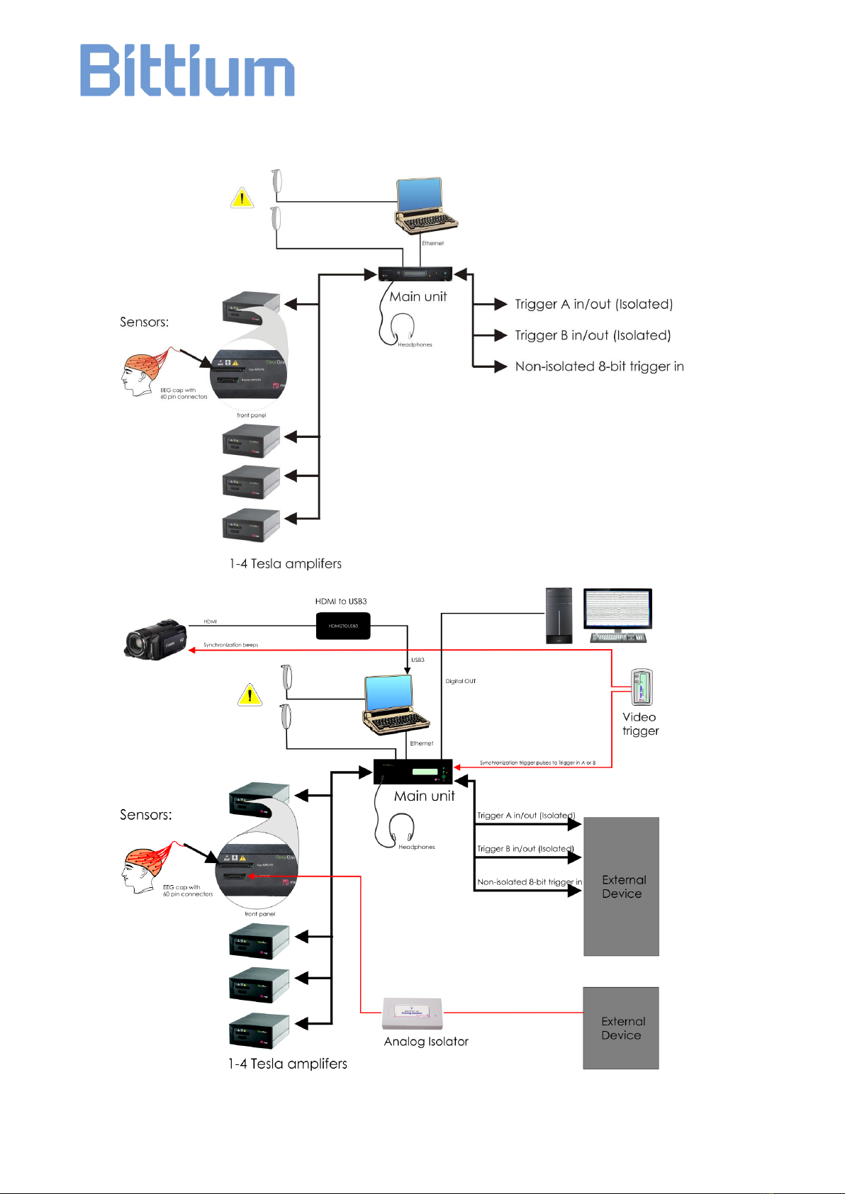
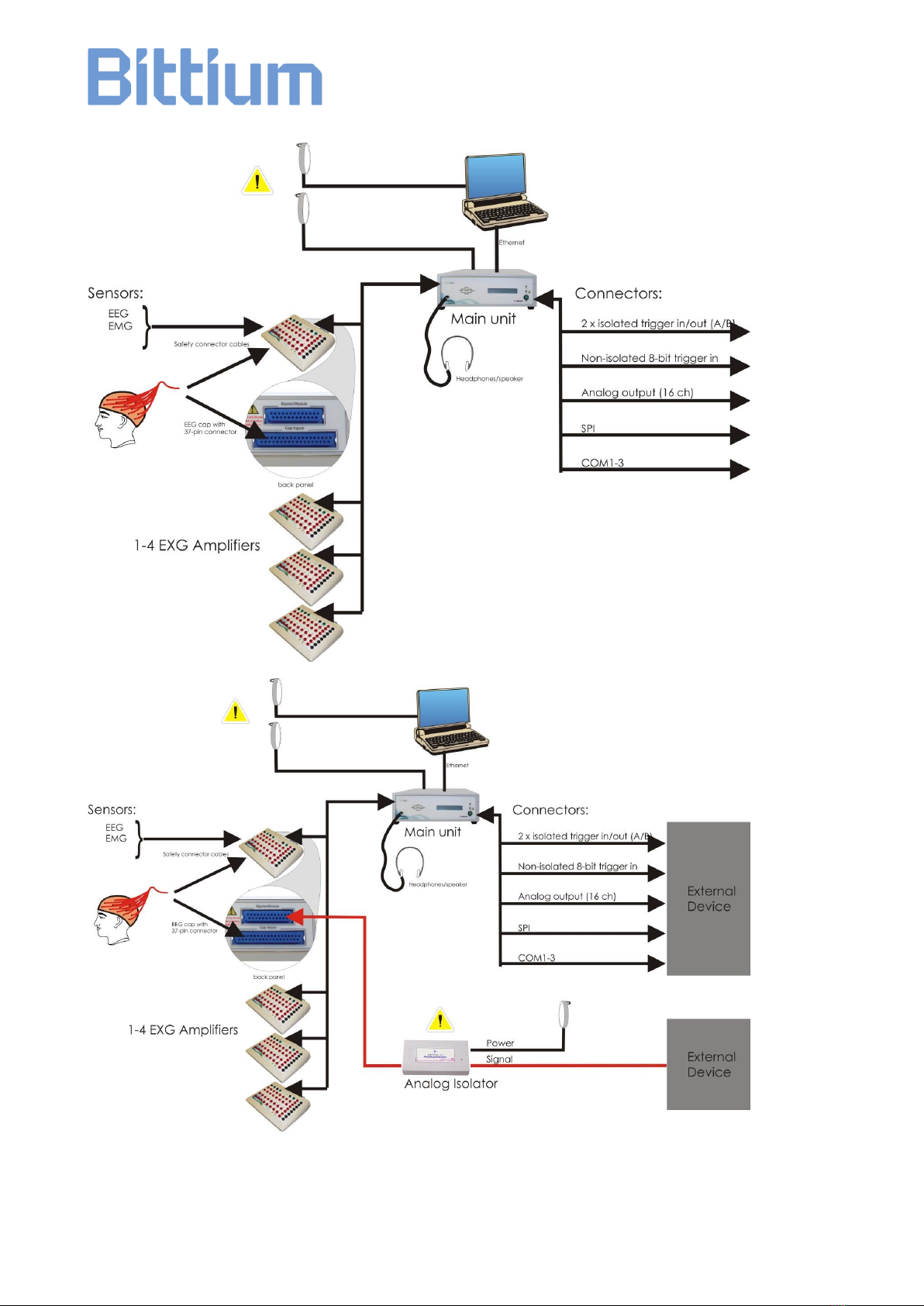
2.2 System Diagrams
Page 13 of 191
800581-2.11 NeurOne System User Manual.doc
Note: SPI and COM port are not yet available and will be enabled by future updates.

Page 14 of 191
800581-2.11 NeurOne System User Manual.doc
2.3 System Functions
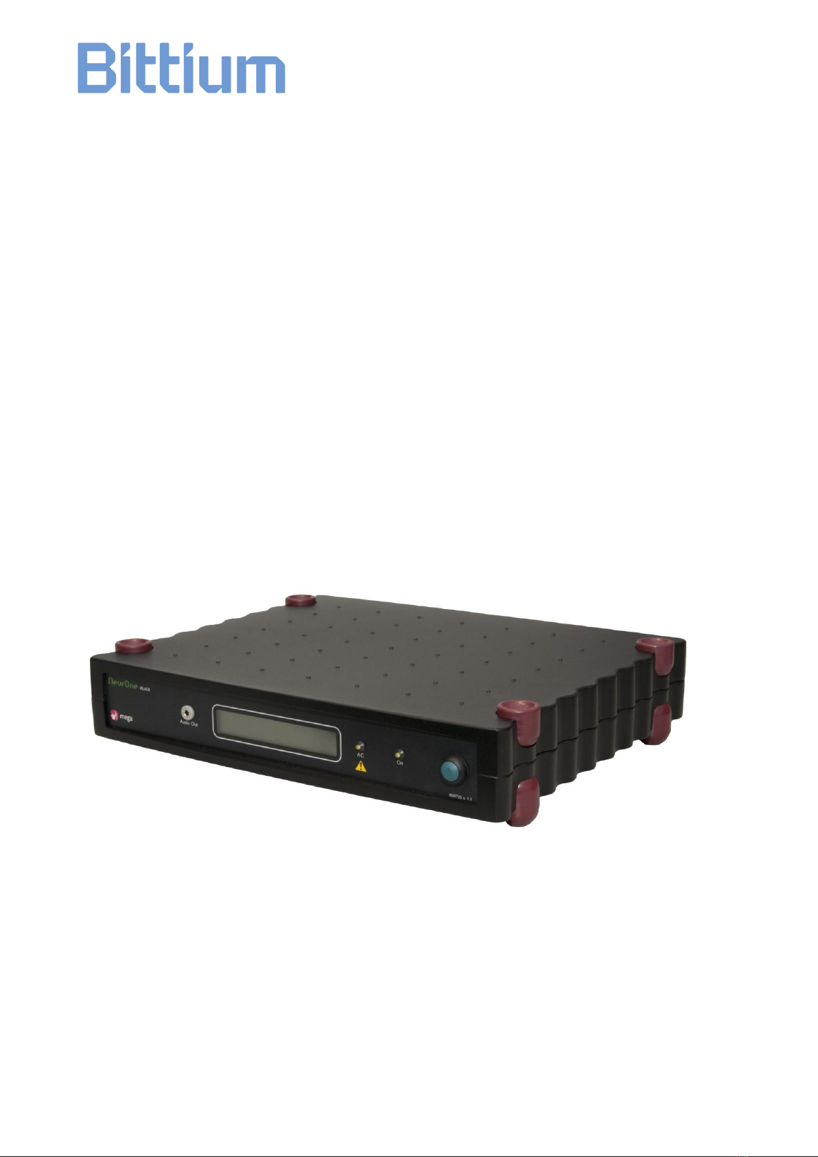
NeurOne System is a monitoring solution for neuroscience measurements. It is
developed for the needs of medical professionals and scientists to detect high
accuracy neurological signals from multiple channels simultaneously without
compromising data integrity. §
System consists of NeurOne Main unit (NeurOne Black) and up to 4 Tesla amplifiers
which are used to collect polygraphic biosignals (EEG, ECG and EMG etc.). One Tesla
amplifier can measure up to 32 unipolar and 8 bipolar channels. Complete NeurOne
system with 4 Tesla amplifiers can measure 160 channels. NeurOne system includes
NeurOne PC operating software which must be installed on the PC. EEG caps, ECG
and EMG electrodes are used as the sensors.
NeurOne PC-software has tools to control all measurement related functionality
commanding NeurOne Main unit through an Ethernet connection. The Main unit
controls the Tesla amplifiers and consolidates incoming data from the amplifiers to a
common data stream that’s sent to the PC. Incoming event triggers are fused to data
stream in the Main unit. Audio output from defined sources takes place in Main unit.
Tesla amplifiers are connected to the NeurOne Main unit via an optic link.
Synchronized measurement takes place in Tesla amplifiers: data acquisition, filtering
and down sampling.
NeurOne PC stores the measured data and provides viewing tools and possibilities to
export data to be used in other applications.
2.4 Usability
The Operator profile for this device is: Healthcare professionals / EEG researcher with
up to date basic computer skills.
The operating principle of the device is designed to keep the operator profile in mind. If
the user is not familiar with EEG measurements, patient isolation principles or result
interpretations it is recommended to have knowledge of this area prior use of this
device.
The device operation does not require repeatable maneuvers which could have
ergonomic influences.
When the system is used with computer and its accessories, please read the computer
manufacturers ergonomic guidelines. It is computer manufacturer’s responsibility to
provide guidelines for proper workstation setup, posture, and health and work habits for
computer users.

Page 15 of 191
800581-2.11 NeurOne System User Manual.doc
2.5 Maintenance and Service
Please follow the maintenance and calibration instructions. You should inspect the
system devices and cables regularly. If there is visible damage, it is best to have it
repaired at your local distributor or Bittium Biosignals Ltd.
2.5.1 Cleaning
You can clean the device using a non-fluffing cloth dampened in cleaning fluid, such as
water and mild hand soap solution. For accessories, like EEG cap, follow the
instructions provided with the accessory.
Disconnect the power supply before cleaning. Be careful not to rub too
forcefully. Do not use alcohol based fluids or corrosive chemicals! Do
not sink the device or cables into the cleaning fluid!
2.5.2 Calibration
The equipment is calibrated at the factory and it does not require regular calibration.
Do not try to open the device, the Power Supply, the cables or other
sealed parts of the system. Only technical personnel, authorized by
Bittium Biosignals Ltd, are allowed to open these parts, subject to the
instructions given by Bittium Biosignals.
2.6 Disposal and Environmental Issues
The packaging material is cardboard. It can be re-cycled according to local regulations.
When the device is not used, consider disconnecting it from the mains current. Note
also that when the device is used according to instructions the service need for the
device is minimized and the life time of the device is optimized.
Please follow your local environment safety regulations when disposing of the system,
or any parts of it. In many countries the electronics re-cycling is possible or even
obligatory.
For EU only: This symbol indicates that this device shall be disposed according
to European Union directive 2002/96/EC on Waste Electrical and Electronic
Equipment (WEEE). If the device is contaminated the directive does not apply.

Page 16 of 191
800581-2.11 NeurOne System User Manual.doc
3
3
S
SO
OF
FT
TW
WA
AR
RE
E
I
IN
NS
ST
TA
AL
LL
LA
AT
TI
IO
ON
N
3.1 System Requirements for the Computer
The NeurOne PC Software requires the following hardware specifications as a
minimum:
Processor: Intel i5 3.0 GHz or better
Screen Resolution: Full HD 1920x1080
Memory (RAM): 4 GB
Graphics card: 1 GB internal memory, dedicated graphics
(DirectX 10 compatibility recommended)
Hard Drive: 1 TB (1000 GB)
Optical Drive: DVD-ROM
Ethernet port: RJ45, 100 / 1000 Mb/s
USB: One USB3 port for video option
Operating System: Windows 7 Professional 64 bit
Recommended PC requirements:
Processor: Intel i7 3.0 GHz or better
Screen Resolution: Full HD 1920x1080
Memory (RAM): 8 GB
Graphics card: 1 GB internal memory, dedicated graphics
(DirectX 10 compatibility recommended)
Hard Drive: 1 TB (1000 GB)
Optical Drive: DVD-ROM
Ethernet port (2 pcs): RJ45, 100 / 1000 Mb/s
USB: One USB3 port for video option
Operating System: Windows 7 Professional 64 bit
3.2 Video Camera Requirements for NeurOne Video Option
When using NeurOne Video Option, the requirements for video camera are:
Video resolution: Full HD (1080p)
Audio Input: Microphone Input
Video Output: HDMI Output

Page 17 of 191
800581-2.11 NeurOne System User Manual.doc
3.3 Installing the NeurOne PC Software
If you are upgrading to NeurOne PC Software v.1.5.x from NeurOne PC Software
version older than 1.4.1.55 you must first install NeurOne 1.4.1.64 and manually back
up your database. Manual database backup is done by copying NeurOneDB.mdf and
NeurOneDB_log.ldf in database folder (default: C:\ProgramData\Mega
Electronics Ltd\NeurOne64\) to a safe location when NeurOne software isn’t
running.
Then install new version 1.5.x as instructed in this chapter.
NeurOne PC Software is a 64-bit application. It uses the Microsoft .NET Framework
4.0, Microsoft Visual C++ 2015 redistributable library and Microsoft SQL Server 2014
Express. The installer will install or update these system parts automatically if they are
not found. Installing the NeurOne PC Software, and the above software components
requires administrative rights on the Windows operating system.
Restart the PC prior to installation.
The installation should start automatically when the installation DVD is inserted into PC
(installation package –NeurOne Installer <version>.exe). The following dialog should
appear (see picture below):
The dialog informs you what components are needed to be installed. Click Install. If you
already have all required requisites installed, this dialog will not be shown.
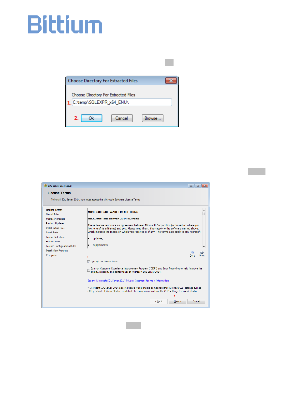
3.3.1 SQL Server 2014 Installation
Page 18 of 191
800581-2.11 NeurOne System User Manual.doc
SQL Server installer will open with extraction path of the installation files. Make sure
that the name of the directory that the files will be installed is short. For example you
can (1) select the folder C:\temp and (2) press OK.
After extraction the installer automatically starts installation of a new database server
instance
Then opens the license terms page. (1) Check “I accept license terms.” and (2) click Next >.
If Microsoft Update is requested click Next>
(DO NOT CHECK THE CHECKBOX)

Page 19 of 191
800581-2.11 NeurOne System User Manual.doc
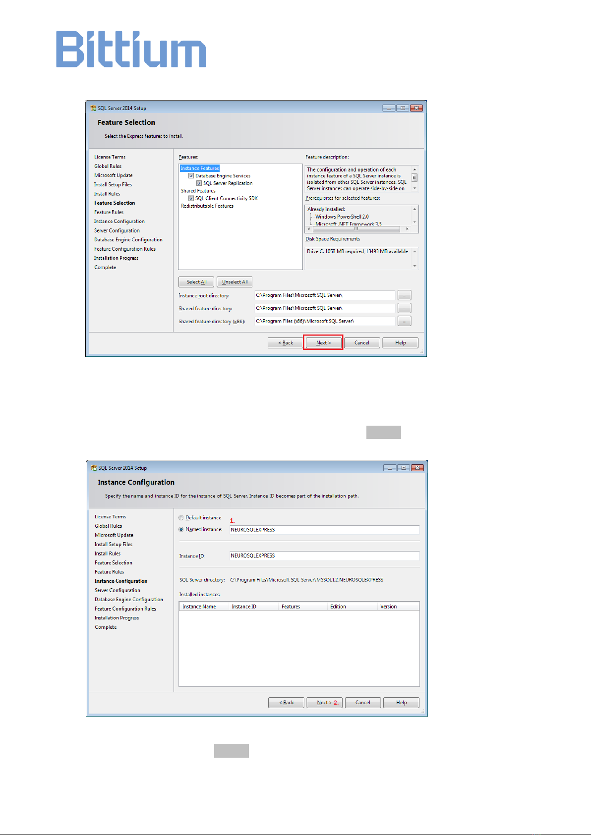
At Product updates click Next>
On the feature selection page make sure all features are selected and click Next >.
Page 20 of 191
800581-2.11 NeurOne System User Manual.doc
On the Instance configuration page (1) ensure that the Named instance and Instance ID
fields are set to value NEUROSQLEXPRESS and (2) click Next >
On Server Configuration click Next >
Table of contents
Other Bittium Medical Equipment manuals

Bittium
Bittium OmegaSnap 3-CH ECG Electrode User manual

Bittium
Bittium Respiro User manual

Bittium
Bittium OmegaSnap User manual

Bittium
Bittium HSAT User manual

Bittium
Bittium OmegaSnap 2-CH ECG User manual

Bittium
Bittium MiniSnap Sensitive 1-CH ECG Electrode User manual

Bittium
Bittium OmegaSnap 1-CH ECG Electrode User manual


