Bizerba VS 12 User manual
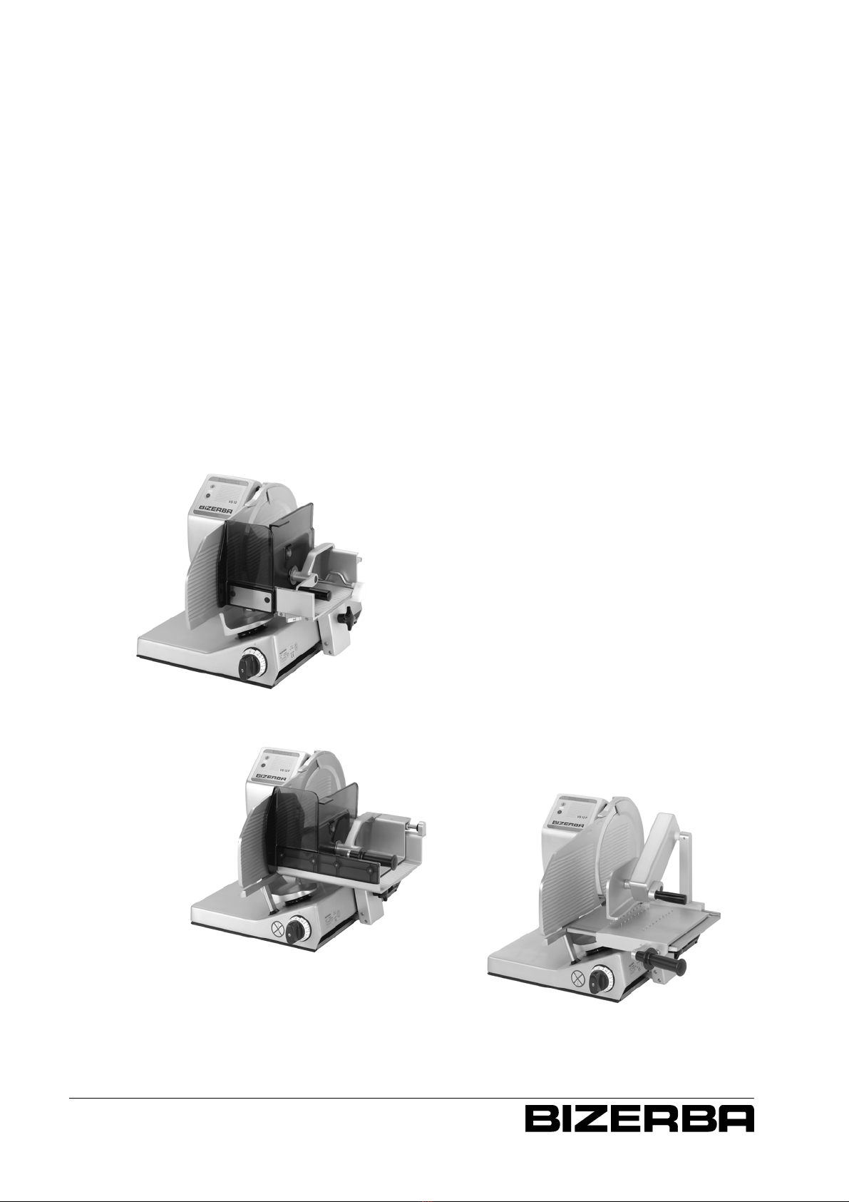
VS 12
VS 12 F--P
VS 12 F
Slicer
VS 12
Operating Instructions
6.080.98.5.10.03

6.080.98.5.10.03Translation of original operating instructions
Alle Rechte vorbehalten
All rights reserved
Tous droits réservés
Reservados todos los derechos
Tutti i diritti riservati
E05 / 2010
Bizerba GmbH & Co. KG,
72336 Balingen
Postfach 10 01 64
72301 Balingen/Germany,
Tel. (+49 7433) 12--0, Fax (+49 7433) 12--2696
e--mail: [email protected]
Internet: http://www.bizerba.com

Date: 27.05.2010
Manufacturer’s signature: ppa. ......................................................................
Signatory’s position: Martin Arndt
Chief Executive Officer Technology (CEO--T)
Bizerba GmbH & Co. KG
Hauptverwaltung Balingen
Postfach 10 01 64, 72301 Balingen
Wilhelm--Kraut--Straße 65
72336 Balingen, Germany
6.080.98.5.10.03
Declaration of conformity
We hereby declare that the design of the machine described below
Description: Slicer
Type: VS12, VS12--S, VS12--T, VS12--S/T,
VS12C, VS12C W, VS12C F,
VS12F, VS12F33, VS12F33--W,
VS12F37, VS12F--W, VS12F--W/T,
VS12F--P, VS12F--P/N, VS12F--P/W,
VS12F--P/N/W, VS12F37--P/N,
VS12F37--P/N/W,
VS12--W, VS12--W/T, VS12--W/S
the applicable requirements in the following EC guidelines:
EC machine guideline 2006/42/EC
EC EMC Guideline 2004/108/EC
Authorized person for combination of technical key documents:
Berthold Roller, Director Quality Management, Bizerba GmbH & Co. KG
The basis for the Declaration of Conformity is the contract documents
(Bizerba order documents). This declaration will lose its validity in the event of
modifications to the above--described device type which have not been agreed with
Bizerba or performed by Bizerba.


6.080.98.5.10.03
VS 12
VS 12 F/VS 12 F--P/VS 12 W/VS 12 C
OPERATING INSTRUCTIONS
1

1
2
3
4
List of Contents
6.080.98.5.10.03
PAGE
GENERAL 4...............................
1.1 Warranty 4.......................................
1.2 Warning notice 5..................................
1.3 Overview/component description 6..................
1.3.1 VS 12 6..........................................
1.3.2 VS 12 F 7........................................
1.3.3 VS 12 F--P 8......................................
1.3.4 VS 12 W 9.......................................
1.4 Dimensional drawing/technical data 10................
1.4.1 VS 12 10..........................................
1.4.2 VS 12 F 11........................................
1.4.3 VS 12 F--P 12......................................
1.4.4 VS 12 W 13.......................................
1.5 Machine description 14.............................
1.6 Products to be cut/application/environmental influences 15..
INSTALLATION 16..........................
2.1 Transport and storage 16...........................
2.2 Installation 16......................................
PAGE
2.3 Electrical connection 17.............................
OPERATING ELEMENTS 18..................
3.1 Keyboard 18.......................................
3.2 Slice thickness setting 19...........................
3.3 Product holder 19..................................
3.3.1 VS 12/VS 12 F/VS 12 W 19..........................
3.3.2 VS 12 F--P 20......................................
3.4 Product fixation device 20...........................
3.5 Bias cut slicing device 21............................
3.6 Feeding carriage 21................................
3.7 Scale 22..........................................
3.8 Weighing operation 23..............................
3.9 Error messages 26.................................
OPERATION/SLICING 28....................
4.1 Long products 28..................................
4.1.1 VS 12/VS 12 W 28.................................
2

5
6
7
8
6.080.98.5.10.03
List of Contents
PAGE
4.1.2 VS 12 F 30........................................
4.1.3 VS 12 F--P 32......................................
4.2 Short products (product ends) 34.....................
4.2.1 VS 12/VS 12 W 34.................................
4.2.2 VS 12 F 36........................................
4.2.3 VS 12 F--P 38......................................
4.3 VS 12/VS 12 W Option: bias cut slicing device 40......
4.3.1 Bias cut with long products 40.......................
4.3.2 Bias cut with short products 42.......................
CLEANING 44..............................
5.1 Preparing for cleaning 44............................
5.2 Cleaning 48.......................................
5.3 Cleaning plan VS 12 50.............................
5.4 Making the machine ready to operate 52..............
BLADE SHARPENING 56....................
6.1 Sharpener 56......................................
6.2 Preparing for sharpening 56.........................
6.3 Attaching of sharpener 57...........................
PAGE
6.4 Sharpening 58.....................................
6.5 Honing 58.........................................
6.6 Removing of sharpener 59..........................
6.7 Removing of sharpening dust 60.....................
ACCESSORIES 62..........................
7.1 Sanitizing/Maintenance/Servicing 62..................
7.2 Disturbances 63...................................
7.3 Optional equipment 63..............................
OPERATING CONDITIONS 64................
8.1 EC directives 64...................................
8.2 Power supply 64...................................
8.3 Air convection 65...................................
8.4 Limiting values for protection type, temperature and air
humidity 65........................................
3

1.1 Warranty GENERAL
6.080.98.5.10.03
Contact us or your local after--sales service, if
any information is not properly understood.
SEquipment should only be transported and
stored in its original packing.
SEquipment should not be started up before
the requirements of the Bizerba operating
conditions are met.
SThe supporting area must be horizontal,
level, stable and non--slippery. Equipment
must be arranged in such a way as to
facilitate operation, working procedures
and service.
SInstallation, commissioning, initial
introduction, cleaning, maintenance and
servicing should only be carried out by the
relevant BIZERBA after--sales service or
by companies or personnel authorized by
BIZERBA.
SThe use of hardware and software which
may be necessary for a data dialog
between BIZERBA and non--BIZERBA
equipment is subject to written approval
from BIZERBA.
SEquipment should not be set into operation
before supervisory and operating
personnel have thoroughly read and
understood these operating instructions.
SThis machine is a technical work resource
which is only suitable for application at
work.
SOnly trained personnel over 14 years
should operate the equipment. Training
should be repeated.
SBIZERBA does not accept liability for
damage arising as a result of installation by
anyone other than
BIZERBA--incorporated or designated
representatives, faulty electrical
connection by the user, improper
operation, inappropriate use, modification
of equipment in any way from its original
form, removal of guards, the use of spare
parts and accessories other than genuine
BIZERBA parts or accessories.
SThe user will be responsible for any
damage or injury arising as a result of
failure to observe the BIZERBA
instructions.
STherefore, it is strongly recommended to
use only genuine BIZERBA spare parts
and accessories.
SNormal wear and tear is not covered by the
guarantee.
To provide operational
assurance and to protect
personnel from possible
injuries, the requirements of
these instructions must be met
before the machine is set into
operation and during operation.
These instructions are subject to revision as
further product development, experience and
investigation may show is necessary or
desirable. Graphics appearing in these
instructions may differ slightly from the model
supplied due to country--specific regulations.
This does not affect the contents of these
operating instructions.
4

1.2 Warning notice
6.080.98.5.10.03
GENERAL INSTALLATION OPERATING
ELEMENTS
OPERATION/
SLICING CLEANING BLADE
SHARPENING ACCESSORIES OPERATING
CONDITIONS
The following warning notice
serves for your own safety.
Failure to comply with it could
result in serious bodily injury.
SFor the space required, see the technical
data as per section 1.4.
SWhen operating the machine, pay special
attention to all movable parts, especially to
the blade and carriage.
SPrevent untrained personnel and
especially children from operating the
machine. Keep them away from the
operating area of the machine.
SPeople with pacemakers should consult a
doctor before operating the machine
(magnetic field).
SDo not tamper with any protective devices
of machine. Do not remove, change or
bypass them. It may result in serious bodily
injury.
SOperate concentrated.
SDo not use machine for products other
than stated in the operating instructions.
SDo not cut frozen products.
SHave damaged power cable immediately
replaced by a qualified and certified
electrician or the relevant BIZERBA
after--sales service.
SKeep working place clean and dry. Provide
non--slippery supporting area.
SKeep machine free of foreign objects.
SBefore cleaning the machine, always
disconnect power cable from the mains.
SImmediately switch machine off if there is
any rough operation or obstruction.
SContact the relevant BIZERBA after--sales
service if you cannot eliminate occurring
malfunctions yourself. 5
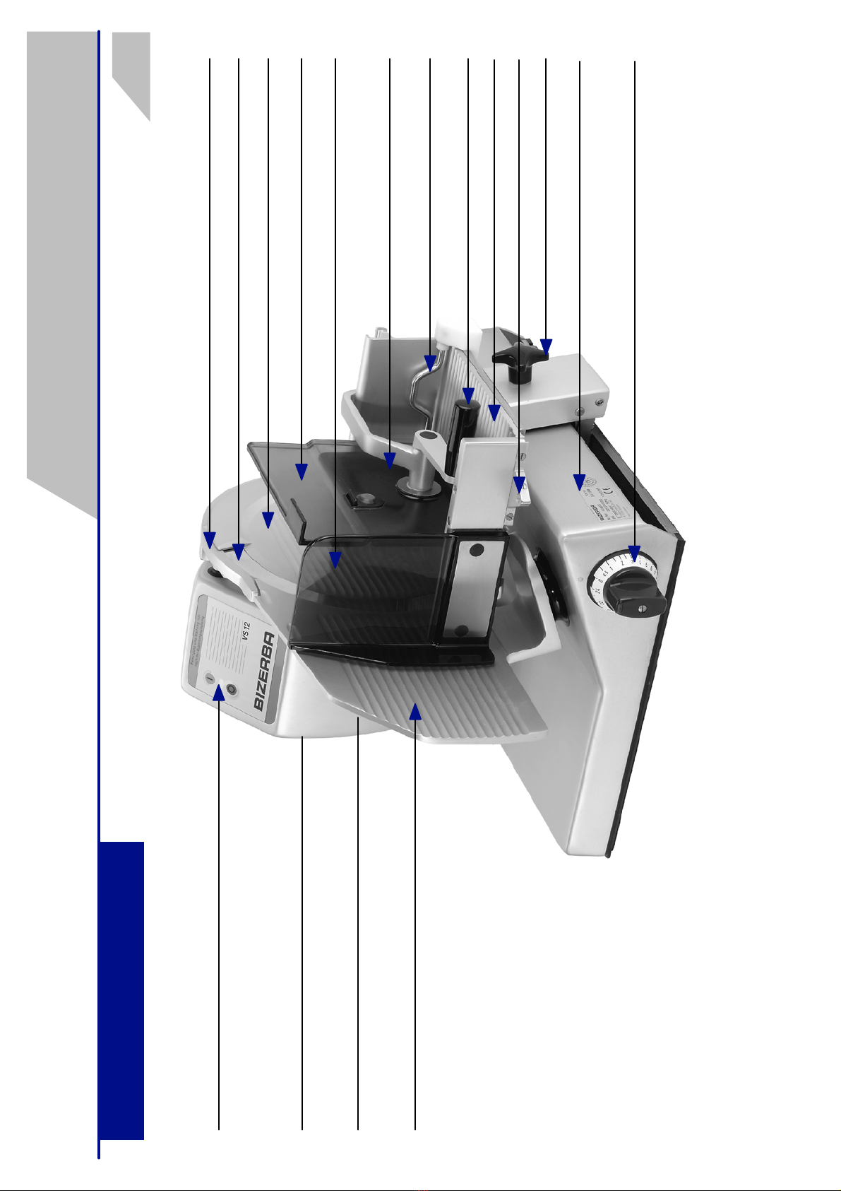
1.3 Overview/component description
1.3.1 VS 12
GENERAL
6.080.98.5.10.03
Blade cover
Accessory kit (not illustrated), containing:
sharpener, special cardboard, cloth, handbrush
with special flat brush, BIZERBA oiler
Deflector
Gauge plate
Keyboard ON/OFF
with pilot lamp
Remnant holder plate
Knob for carriage
Handle for product holder
Carriage
Specification plate: CE symbol
GS plate
Slice thickness control knob
Rear wall
Product fixation device
Blade guard ring
Blade
Guard plate
Three--square knob for blade cover
Bias cut plate
6
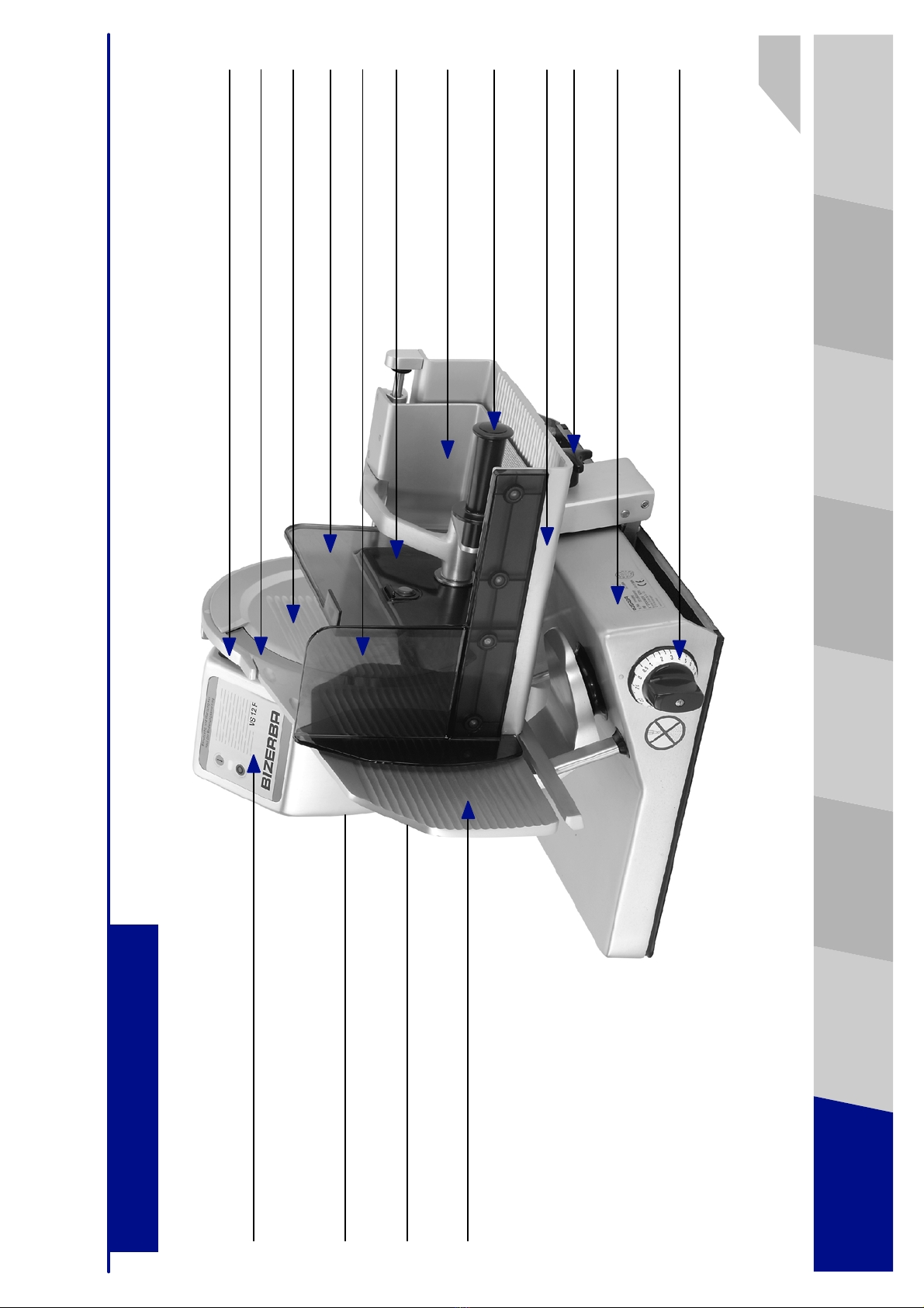
1.3.2 VS 12 F
6.080.98.5.10.03
GENERAL INSTALLATION OPERATING
ELEMENTS
OPERATION/
SLICING CLEANING BLADE
SHARPENING ACCESSORIES OPERATING
CONDITIONS
Guard plate
Accessory kit (not illustrated), containing:
sharpener, special cardboard, cloth, handbrush
with special flat brush, BIZERBA oiler
Three--square knob for blade cover
Deflector
Gauge plate
Keyboard ON/OFF
with pilot lamp
Rear wall
Knob for carriage
Handle for product holder
Carriage
Specification plate: CE symbol
GS plate
Slice thickness control knob
Feeding carriage
Remnant holder plate
Blade guard ring
Blade
Blade cover
7

1.3.3 VS 12 F--P
GENERAL
6.080.98.5.10.03
Accessory kit (not illustrated), containing:
sharpener, special cardboard, cloth, handbrush
with special flat brush, BIZERBA oiler
Three--square knob for blade cover
Deflector
Gauge plate
Keyboard ON/OFF
with pilot lamp Blade cover
Product holder
Knob for carriage
Handle for product holder
Carriage
Specification plate: CE symbol
GS plate
Slice thickness control knob
Feeding carriage
Handle for feeding carriage/carriage
Blade guard ring
Blade
8

1.3.4 VS 12 W
6.080.98.5.10.03
GENERAL INSTALLATION OPERATING
ELEMENTS
OPERATION/
SLICING CLEANING BLADE
SHARPENING ACCESSORIES OPERATING
CONDITIONS
Blade cover
Accessory kit (not illustrated), containing:
sharpener, special cardboard, cloth, handbrush
with special flat brush, BIZERBA oiler
Deflector
Gauge plate
Keyboard ON/OFF
with pilot lamp
Remnant holder plate
Knob for Carriage
Handle for product holder
Carriage
Specification plate: CE symbol
GS plate
Slice thickness control knob
Rear wall
Product fixation device
Blade guard ring
Blade
Guard plate
Three--square knob for blade cover
Load plate
9

1.4 Dimensional drawing/technical data
1.4.1 VS 12
GENERAL
6.080.98.5.10.03
Dead weight = approx. 40,4 kg
Blade diameter = 330 mm
Number of blade revolutions = 266 r.p.m.
THE MOST IMPORTANT TECHNICAL DATA
Product size --round = 224 mm
--rectangular = 224 x 260 mm
Slice thickness control, = 0,5 to 24 mm
infinitely variable
Type of current, voltage, = see specification plate
power consumption
LENGTH
Outside dimensions
LBH
625 mm 570 mm 432 mm
Supporting area
L1 B1
(300) 520 mm (420) 430 mm
Processing area
L2 B2
740 mm672 mm
WIDTH
B1
B
B2
H
L1
L
L2
(L1) (B1)
100/120 mm
L1a/L1b
L1a L1b
10
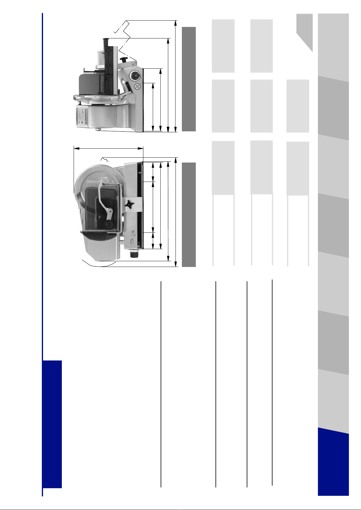
1.4.2 VS 12 F
6.080.98.5.10.03
GENERAL INSTALLATION OPERATING
ELEMENTS
OPERATION/
SLICING CLEANING BLADE
SHARPENING ACCESSORIES OPERATING
CONDITIONS
Dead weight = approx. 47,5 kg
= approx. 105 lbs
Blade diameter = 350 mm
= 13.78”
Number of blade revolutions = 266 r.p.m.
THE MOST IMPORTANT TECHNICAL DATA
Product size --round = 270 mm
= 10.63”
--rectangular = 260 x 315 mm
= 10.24” x 12.40”
Slice thickness control, = 0,5 to 24 mm
infinitely variable = 0.02 to 0.94”
Type of current, voltage, = see specification plate
power consumption
LENGTH
Outside dimensions
LBH
706 mm
27.80”
674 mm
26.53”
480 mm
18.90”
Supporting area
L1 B1
(385) 605 mm
(15.16) 23.82”
(425) 430 mm
(16.73) 16.93”
Processing area
L2 B2
770 mm
30.31”
860 mm
33.86”
WIDTH
B1
B
B2
H
L1
L
L2
(B1)(L1)L1a L1b
100/120 mm
3.94/4.72”
L1a/L1b
11

1.4.3 VS 12 F--P
GENERAL
6.080.98.5.10.03
Dead weight = approx. 50,3 kg
= approx. 111 lbs
Blade diameter = 350 mm
= 13.78”
Number of blade revolutions = 266 r.p.m.
THE MOST IMPORTANT TECHNICAL DATA
Product size --round = 270 mm
= 10.63”
--rectangular = 260 x 325 mm
= 10.24” x 12.80”
Slice thickness control, = 0,5 to 24 mm
infinitely variable = 0.02 to 0.94”
Type of current, voltage, = see specification plate
power consumption
LENGTH
Outside dimensions
LBH
706 mm
27.80”
695 mm
27.36”
480 mm
18.90”
Supporting area
L1 B1
(385) 605 mm
(15.16) 23.82”
(425) 430 mm
(16.73) 16.93”
Processing area
L2 B2
730 mm
28.74”
890 mm
35.04”
WIDTH
B1
B
B2
H
L1
L
L2
(B1)
(L1)
100/120 mm
3.94/4.72”
L1a/L1b
L1a L1b
12

1.4.4 VS 12 W
6.080.98.5.10.03
GENERAL INSTALLATION OPERATING
ELEMENTS
OPERATION/
SLICING CLEANING BLADE
SHARPENING ACCESSORIES OPERATING
CONDITIONS
Dead weight = approx. 42,9 kg
Blade diameter = 330 mm
Number of blade revolutions = 266 r.p.m.
THE MOST IMPORTANT TECHNICAL DATA
Product size --round = 224 mm
--rectangular = 224 x 260 mm
Slice thickness control, = 0,5 to 24 mm
infinitely variable
Type of current, voltage, = see specification plate
power consumption
LENGTH
Outside dimensions
LBH
625 mm 585 mm 432 mm
Supporting area
L1 B1
(300) 520 mm (420) 430 mm
Processing area
L2 B2
755 mm672 mm
WIDTH
B1
B
B2
H
L1
L
L2
(L1) (B1)
100/120 mm
L1a/L1b
L1a L1b
13

1.5 Machine description GENERAL
6.080.98.5.10.03
The machine is designed with the following
guards and protective devices:
The complete machine housing, the gauge
plate, the blade cover, the carriage, the
feeding carriage and the remnant holder plate
of the VS 12 F--P are made of anodized
aluminium.
VS 12 C/VS 12 C W/VS 12 C F
Surface refinement with Ceraclean.
The rear wall,theguard plate and the
remnant holder plate of the
VS 12/VS 12 F/VS 12 W are of transparent,
fracture--resistant and foodstuff--friendly
plastics. All materials used in the food zone
and processing area are designed in
conformity with the applicable sanitation
requirements. All bearings in the visual area
are lubricated with lubricating agents
permitted for use in food zones.
All function keys are integrated into the
operating and display foil. The green ON
and red OFF pushbuttons use a pilot lamp to
control the start of the machine. The red
pushbutton responds already at a slight
touch. A control contactor with a self--holding
circuit prevents the machine from being
automatically restarted after power failure. A
slice thickness setting below ’0’ unlocks the
tilting safety device allowing the carriage to be
tilted in any position.
Sblade guard ring, stationary,
non--removable
Senclosed blade cover, stationary,
removable
Sgauge plate, covering the stroke area
Sprotective circuit to provide protection in
case of power failure
Ssharpener with protective cover of the
exposed blade area
VS 12/VS 12 F/VS 12 W
Srear wall, non--removable
Sunstable equilibrium of product holder in its
upper position
Sforce--guided product holder in a cutting
area of < 60 mm
This gravity feed slicer has the blade
power--driven. An a. c. or three--phase motor
drives the machine via a ribbed belt in almost
noiseless operation.
The product is fed toward the blade by
manually moving the carriage forth and back.
To enhance the frictional property of the
product, all parts coming into contact with the
product are provided with grooves.
VS 12/VS 12 W
The carriage is provided with an additional
product fixation device which prevents the
product from slipping and moving
downwards.
VS 12/VS 12 F/VS 12 W
To position the product to be cut, the product
holder may be swivelled up to its unstable
equilibrium.
VS 12 F/VS 12 F--P
The carriage equipped with an additional
feeding carriage is especially suitable for
cutting of large--surface products.
VS 12 F--P
The product holder is designed with a
clamping device.
VS 12 W
The slicing machine using an integrated scale
permits the sliced product to be
simultaneously weighed.
14

1.6 Products to be cut/application/environmental influences
6.080.98.5.10.03
GENERAL INSTALLATION OPERATING
ELEMENTS
OPERATION/
SLICING CLEANING BLADE
SHARPENING ACCESSORIES OPERATING
CONDITIONS
Sall types of sausage
Sham/bacon
Ssmoked meat with/without rind
Sroast/roast beef
Smeat/meat rolls
Scheese
Sbread
Pay attention to permitted size of
product
Do not cut:
Note
SIf mainly cutting cheese, the use of a
special cheese knife is recommended.
See optional equipment.
Application
SThe slicer is designed for application in
salerooms. It is also permitted for use
under wet environmental conditions by
taking into account the cleaning plan and
protection type IP33.
Operating time
SDesigned for continuous operation.
Working place--related emission
noise level value
SLpA =53dB(A).
SThe value takes into consideration an
instable measuring of 3 dB.
Vibration
SThe total vibration of the items, Which get
into contact with hand and arm is below
2.5m/s2 and therefore below the required
limited value.
Humidity
SProtection type IP 33. High air humidity or
moisture condensation occurring on the
machine may result in machine damage.
Temperature
SPermissible ambient temperatures:
-- 1 0 °Cto+40°C
Products permitted for cutting:
SNON FOOD products
Sbone--in products
Sfrozen food
otherwise you will damage the machine
and risk bodily injury.
15

2.1 Transport and storage
When transporting the machine shoes with steel caps should be worn and
lifting devices should be used.
At least two persons are necessary to move the machine.
Weight of machine is higher than 25 kg.
INSTALLATION
6.080.98.5.10.03
2.2 Installation
Only lift the machine out of the packaging by the
lifting straps. The drawing ”Packing/unpacking
the machine” is included.
Pay attention to the required space (see section
1.4).
Recommended height of working table:
approximately 800 mm
Requirements to be met by the supporting
area:
Shorizontal and level surface
Sstable and non--slippery
Srigid (for the machine weight,
see section 1.4)
16
Convey and store the
machine according to
the symbols indicated on
the packaging.
The lifting straps must only
be used for machine hand-
ling until it is unpacked.
They must not be used as
load--carrying equipment.
Be careful when un-
packing!
Carriage might
move due to its un-
laden weight.
This manual suits for next models
3
Table of contents
Other Bizerba Kitchen Appliance manuals

Bizerba
Bizerba VSI330 F User manual

Bizerba
Bizerba FW N22 User manual

Bizerba
Bizerba GSP H User manual

Bizerba
Bizerba VS12D User manual

Bizerba
Bizerba SE 12/18L User manual

Bizerba
Bizerba A400 User manual

Bizerba
Bizerba VS 12 F--P User manual

Bizerba
Bizerba A400 User manual

Bizerba
Bizerba VS 12W User manual

Bizerba
Bizerba A400 User manual


