manuals.online logo
Brands
  1. Home
  2. •
  3. Brands
  4. •
  5. Blaupunkt
  6. •
  7. Radio
  8. •
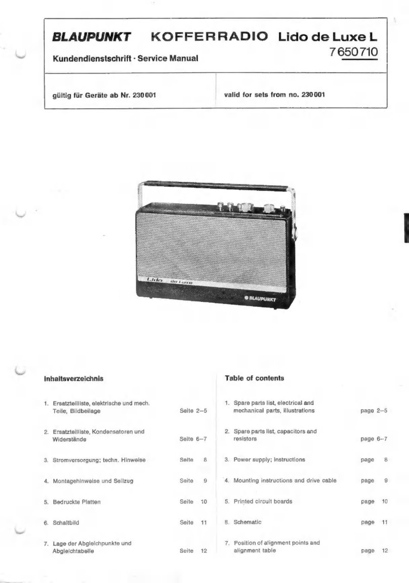
  9. Blaupunkt Sultan User manual

Blaupunkt Sultan User manual

KBD
964-403
BLAUPUNKT-HEIMRADIO
Sultan
7626340
H
601
7626350
Service
Manual
giiltig
fiir
Sultan
7626
340
ab
Nr.
X
120001
valid
for
Sultan
7
626 340
from
No.
X
120
001
giiltig
fir
H601
7626350
ab
Nr.
X
115001
valid
for
H601
7626350
from
No.
X
115001
Sultan
7
626
340
H
601
7626
350
Bedienungsknépfe
Control
knobs
Linke
Knopfgruppe
LH
group
of
knobs
links:
Lautstarkeregler
|
LH:
volume
control
Mitte:
Babregler
centre:
bass
contro]
rechts:
Sopranregler
RH:
treble
control
Rechte
Knopfgruppe
~
RH
group
of
knobs
oben:
Abstimmung
fir
LW,
MW
above:
tuning
of
LW,
MW
and
16
to
41
m
SW
band
und
16-41
m
KW-Band
below:
tuning
of
FM,
49
m
Europe
band,
and
SW
banda-
unten:
Abstimmung
fir
UKW,
49m
Europaband
und
spread
for
16
to
41m
band
KW-Lupe
fir
16-41
m
Band
Inhaltsverzeichnis
|
Table
of
Contents
1.
Ersatzteilliste,
elektrische
u.
mech.
Teiie
Seite
2—5
1.
Spare
parts
list,
electrical
and
2.
Ersatzteiliiste,
Kondensatoren
und
|
mechanical
parts
page
2—5
Widerstande
Seite
6—7
2.
Spare
parts
list,
capacitors
and
resistors
page
6—7
3.
Abgleich
Seite
8
3.
Alignment
page
8
4.
Abgleichtabelle
Seite
9
4.
Alignment
table
page
9
5.
Lage
der
Abgleichpunkte
Seite
9
5.
Position
of
alignment
points
page
9
6.
HF-,
ZF-,
NF-Platte,
PL
1
Seite
10
6.
RF-IF-
AF
board,
PL
1
page
10
7.
Schaltbild
Seite
11-—-12
7..
Schematic
page
11—12
8.
Potentiometer-Platte,
PL
2
Seite
13
8.
Potentiometer
board,
PL
2:
page
13
9.
Seilzige
Seite
13
9.
Drive
cables
page
13
Ersatzteilliste
Eiektrische
und
mechanische
Teile
Lfd.
Nr.
Bestell-Nr.
Pos.
i.
Schaltbild
Bestell-Bezeichnung
Part
Item
Part
No.
Pos.
in
schematic
No.
*
Kennzeichnet
die
einem
VerschleiB
Marks
the
parts
subject
to
a
special
unteriegenen
Teile.
Wir
empfehlen
wear
and
tear.
We
recommend
to
sie
zur
Lagerhaltung.
keep
them
in
stock.
Drucktastensatz
Pushbutton
switch
1
Drucktastensatz,
mech.,
Pushbutton
switch,
mech.
70
SH
6062/04x
2
*
Drucktastenknopf
*
Pushbutton
°6
KF
0231/Oia
3
*
Netzschalter
*
On-off
switch
70
SH
0002/05a
4
|
*
Kontaktschieber
(UKW-49
m)
*
Contact
slide
(FM-49
m)
30
KT
6005/04x
5
|
*
Kontaktschieber
(LW)
*
Contact
slide
(LW)
|
30
KT
6005/08x
6
|
*
Kontaktschieber
*
Contact
slide
(FM
supplement)
30
KT
6005/17x
(FM-Zusatzschieber)
7
|
*
Kontaktschieber
(16-41
m
+
TA)
*
Contact
slide
(16-41
m
+
PU)
30
KT
6005/15x
8
Haltefeder
fur
Kontaktschieber
Retaining
spring
for
contact
slide
68
SF
6022/01x
Bedruckte
Platten
Printed
circuit
boards
20
HF-ZF-NF-Platte,
volist.
RF,
IF
and
AF
board,
compl.
61
PT
6128/21z
PL
4
>
Messerkontakte
(lang)
Knife
contacts
(long)
31
KV
0843/11x
29
Messerkontakte
(kurz)
Knife
contacts
(short)
31
KV
0843/08x
23
Messerkontakte
(doppelt,
kurz)
Knife
contacts
(double,
short)
31
KV
0843/09x
94
Schieberfuhrung
(vorn)
Guide
for
slide
(front)
53
NF
6194/01x
25
Schieberfuhrung
(hinten)
Guide
for
slide
(rear)
53
NF
6194/02x
26
Drahtbugel
Wire
bridge
15
DR
6004/01x
7
AntennenanschluBplatte,
vollst.
Antenna
connection
board,
compl.
05
AT
6021/02z
28
Netztrafoplatte,
volist.
Mains
transformer
board,
compl.
61
PT
6120/21z
PL
5
29
Potentiometerplatte,
vollst.
Potentiometer
board,
compl.
13
CZ
6136/Oiz
PL
2
Spulen
Coils
35
KW-Oszillatorspule
SW
oscillator
coil
87
WC
6169/04z
L
708—710
36
Abstimmkern
Iron
core
(MW)
73
SR
0905/01x
L
708
37
MW
+
LW
Oszillatorspule
MW
+
LW
oscillator
coil
87
WC
6204/01z
L
713-714
38
Abstimmkern
(MW)
Iron
core
(MW)
73
SR
0905/01x
L
713
39
Abstimmkern
(LW)
lron
core
(LW)
73
SR
6008/01x
L
714
40
KW-Vorkreisspule
SW
RF
coil
87
WC
6168/04z
L
703-704
41
Abstimmkern
lron
core
73
SR
0905/01x
L
704
42
ZF-Sperrkreis
IF
rejector
circuit
87
WC
2590/04z
CL
701
43
Abstimmkern
lron
core
73
SR
3478/02x
L
701
Trimmerkondensatoren
Trimmer
capacitors
50
Trimmerkondensator
10—40
pF
Trimmer
capacitor
10—40
pF
81
TK
0715/04x
C
706
51
Trimmerkondensator
3-10
pF
Trimmer
capacitor
3—10
pF
81
TK
0715/03x
©
707
52
Trimmerkondensator
4—20
pF
Trimmer
capacitor
4—20
pF
81
TK
0715/01x
©
709,
710
Drossein
Chokes
60
HF-Drossel
RF
choke
87
WC
6034/0ix
D
701,
705
61
HF-Drossel
RF
choke
87
WC
5023/28x
OD
702,
704
62
HF-Drossel
RF
choke
87
WC
2351/49x
D
703
63
Ferritperle
Ferrite
pearl
40
MF
0767/10n
D
706
64
Ferritperle
Ferrite
pearl
40
MF
0767/20n
OD
838
65
HF-Drossel
RF
choke
87
WC
2351/53x
D
781
66
HF-Drossel
RF
choke
87
WC
2375/01iz
OD
837
Bandfilter
IF
transformers
70
FM-Einzelkreis
FM
single
circuit
91
ZF
6003/01z
L717
71
Abstimmkern
Iron
core
73
SR
3473/01x
L
717
72
AM-FM
Bandfilter
IF
transformer
for
AM-FM
91
ZF
0739/282
L
720—723
73
Abstimmkern
lron
core
73
SR
3473/01x
L
720,
721
Spare
Parts
List
Electrical
and
Mechanical
Parts
|
Lfd.
Nr.
Bestelibezeichnung
Bestell-Nr.
Position
im
Schaltbild
Part
Part
No.
Position
in
schematic
Schichtwiderstande
Composition
resistors
33.Q
+
10%%o
1/8
W
89
WI
2199/07n
R
705
68
Q
+
5
9%/y
1/8
W
89
WI
2199/11n
R715
100
Q
+
5
fq
1/5
W
89
WI
2200/13n
R784
150
Q
+
10%o
1/8
W
89
WI
2199/15n
R
731,
803
180
Q
+
52%/q
1/8
W
89
WI
2199/16n
R703
200
Q
+
5
%%
1/5W
89
WI.
2200/74n
R781,
783
220
Q
+
5g
1/3W
89
WI
2203/17n
R
750
820
Q
+
40
%p
1/8
W
89
WI
2199/24n
R
806
1kQ
+
59/4
1/8
W
89
Wi
2199/25n
R759
1kQ
+
10%
1/3
W
89
WI
2203/96n
R712,
718
1kQ
+
5%
1,5
W
89
WI
2220/25n
R751
2,7
kQ
+
5%7/q
1/8
W
89
WI
2208/30n
R
802
2,7
kQ
+
5%o
1/3
W
89
WI
2203/30n
R752
8,2
kQ
+5
%p
1/5
W
89
WI
2200/36n
R
786
10
kQ
7S
fo
1/8
W
89
WI
2199/37n
R701
15
kQ
+
10%/o
1/8
W
89
WI
2199/39n
R
805
22
kQ
+
10%
1W
89
WI
2205/41n
R710,
711
22
kQ
+
5
%/p
1/8
W
89
WI
2199/41n
R713
33
kQ
+
5
%g
1/8
W
89
WI
2199/43n
R704
39
kQ
+5
4p
1/5W
89
WI
2200/44n
R785
A7
kQ
+
5%
1/8
W
89
WI
2208/45n
R
801
47
kQ
+
10
%/o
1/8
W
89
WI
2199/45n
R
804
56
kQ
F
10%7o
1
Ww
89
WI
2205/46n
R714
82
kQ
ome
|
1/8
W
89
WI
2199/48n
R724
100
kQ
+
10%o
1/8
W
89
WI
2199/49n
R
837,
758,
120
kQ
+
5
%p
1/8
W
89
WI
2199/50n
R720
270
kQ2
+
10
%p
1/8
W
89
WI
2199/54n
R
760
330
kQ
+
5%/g
1/8
W
89
WI
2199/55n
R
727
470
kQ
+
5%
1/8
W
89
WI
2199/57n
R
702
1MQ
+
5%
1/8
W
89
WI
2199/61n
R706,
719,
761
2,2
MQ
+
5%/q
1/8
W
89
WI
2203/65n
R729
10
MQ
+
54/y
1/3
W
89
WI
2203/73n
R757
Abgleich
2.1
Lid
ce
3.2
3.3
Vorbereitung
zum
Abgleich
Skalenzeiger
bei
eingedrehtem
Drehkondensator
auf
die
Markierung
(Mittelwellenskala)
stellen.
Tonblende
auf
,hell",
Kurzwellenlupe
auf
,O"
Laut-
starkeregler
auf
Maximum.
Wechselstrominstrument
oder
Multavi
R
(Ri
=
7500
&2)
an
die
Sekundarseite
des
Ausgangstransformators
an-
schlieken
(50
mW
=
0,5
V
an
der
Sekundarseite
des
Aus-
gangstransformators
gemessen).
AM-Abgleich
ZF-Abgleich:
Mehsender
Uber
einen
Kondensator
von
10
nF
an
G
1
—
ECH
81
<3)
ankoppeln.
ZF-Kreise
in
der
an-
gegebenen
Reihenfolge
auf
Maximum
abstimmen
(s.
Ab-
gleichtabelle).
Zur
Messung
der
ZF-Empfindlichkeit
ist
der
Meksender
Uber
einen
Kondensator
von
10
nF
an
das
G
1
—
ECH
8)
bzw.
G
1
—-
EAF
801
anzuschliehen.
HF-Abgleich:
Sollten
beim
Abgleich
der
MW
und
LW
Sto-
rungen
Uber
die
Ferritantenne
auftreten,
so
sind
die
ZF-
Kreise
L
726
und
L
727
mit
je
10
kQ
zu
bedampfen.
Fur
den
Abgleich
der
Kurzwellenbander
16—41
m
und
49
m
entfallt
die
Dampfung.
Der
Mehsender
wird
tber
die
inter-
nationale
Ersatzantenne
an
die
Antennenbuchse
<1)
an-
geschlossen.
Abgleich
nach
Abgleichtabelle
durchfihren.
FM-Abgleich:
Zum
Messen
der
Richtspannung
ein
Rdéhrenvoltmeter
zwi-
schen
Katode
und
Gitter
3
der
EAF
801
<7)
Uber
einen
Vorwiderstand
von
1
MQ
anschliehen.
Die
Richtspannung
an
G
3
der
EAF
801
soll
beim
Abgleich
immer
0,7
Voli
betragen.
ZF-Abgleich
mit
Meffsender:
Modulierten
Meksender
an
einen
geschlitzten
Metallzylin-
der,
der
Uber
die
ROhre
ECC
85
geschoben
wird,
und
nur
bis
zu
den
Oberkanten
der
Anoden
reichen
darf,
anschliehen.
Kern
von
L
782
herausdrehen.
ZF-Filter
L
781
—
L
111
auf
Maximum
der
Richtspannung
abgleichen.
Dann
L
782
auf
NF-Maximum
am
Outputmeter
abstimmen.
Richtspannung
und
die
Spannung
am
Outputmeter
mussen
auf
Maximum
sein.
Bereichsabgleich:
Meksender
auf
94,5
MHz
einstellen.
Mit
der
UKW-Abstimmung
die
Frequenz
von
94,5
MHz
aufsuchen,
den
Zeiger
auf
die
Frequenzmarke
94,5
MHz
auf
der
Skala
hinschieben
und
C
107
auf
Maximum
ab-
gleichen.
Achtung!
C
113
nur
nachstimmen,
wenn
sich
der
Bereich
verschoben
hat.
NF.
Tongenerator
Uber
eine
RC-Kombination,
100
kQ
parallel
zu
1
000
pF,
an
die
TA-Buchse,
bzw.
an
G
1
-
E(C)L
86
an-
schliehen.
Alignment
2.1
2:2
3.1
3.2
3:3
4,1
Preparation
for
Alignment
Turn
in
tuning
capacitor
and
set
dial
pointer
to
cali-
bration
mark
(MW
dial).
Tone
control
to
“treble”,
SW
bandspread
to
"O"
and
volume
control
to
maximum.
Connect
a
VTIVM
or
Multavi
R
(Ri
=
7500
Q)
to
the
output
transformer
secondary
(50
mW
=
0.5
V
measured
at
the
output
transformer
secondary).
AM
Alignment
IF
alignment:
Connect
signal
generator
via
a
10
nF
capa-
citor
to
the
control
grid
of
tube
ECH
81
<3).
Align
the
IF
circuits
in
given
sequence
to
maximum
(see
alignment
table).
For
measuring
the
IF
sensitivity
connect
signal
generator
via
a
10
nF
capacitor
to
the
control
grid
of
the
tube
ECH
81,
resp.
EAF
801.
RF
alignment:
If,
during
the
alignment
of
MW
and
LW
interference
should
be
present
via
the
ferrite
antenna,
the
IF
circuits
L
726
and
L
727
must
be
damped
with
10
kQ
each.
The
damping
can
be
omitted
for
the
alignment
of
the
SW
bands
16
to
41
m
and
49
m.
The
signal
genera-
tor
is
connected
via
the
dummy
antenna
jack
<1).
Carry
out
alignment
according
to
alignment
table.
FM
Alignment
For
measuring
the
nominal
volfage
connect
a
VIVM
via
a
1
MQ
resistor
between
cathode
and
grid
of
the
EAF
801
<7)
During
alignment,
the
nominal!
voltage
at
G
3
of
the
EAF
801
must
always
be
0.7
V.
IF
alignment
with
signal
generator:
Connect
the
modu-
lated
signal
generator
to
a
slit
tube
shield
(slotted
metal
cylinder)
which
is
slid
on
the
tube
ECC
85
up
to
the
upper
edges
of
the
plate.
Turn
out
core
of
L
782.
Align
IF
transformer
L
781
—
L
111
for
maximum
of
nominal
voltage.
Adjust
L
782
for
AF
maximum
reading
at
the
outputmeter.
The
nominal
voltage
as
well
as
the
voltage
at
the
outputmeter
must
be
at
their
maximum.
Band
alignment:
Set
signal
generator
to
94.5
Mc.
Set
FM
tuning
to
94.5
Mc,
slide
pointer
to
calibration
mark
94.5
Mc
of
the
dial
and
align
C
107
to
maximum.
Attention!
Only
readjust
C
113
if
the
band
has
been
dis-
placed.
AF
Connect
AF
generator
via
a
RC
circuit,
100
k2
in
parallel
with
1000
pF,
to
the
PU
jack,
resp.
to
the
control
grid
of
the
tube
E(C)L
86.
Abgleichtabelle
Alignment
Table
Wellenbereiche
145
—
345
kHz
515
—
1620
kHz
5,95
—
6,25
MHz
7,0
—
18,2
MHz
FM
{UKW]
87,4
—
104
MHz
Wavebands
2069
+
—
869,5
—
345
ke
2069
=
—
869.5
582,5
—
185
——
1620
ke
582.5
—
185
50,43
—
48
49
m
(SW)
6.25
Mc
50.43
—
48
42,86
—
16,5
16—41
m
(SW)
7.00
—
18.2
Me
42.86
—
16.5
3,43
—
2,88
FM
87.4
—
104
Mc
3.43
—
2.88
Hoi
i
aot
Mehsender
Gerat
AM-
und
NF-Empfindlichkeit
bezogen
auf
F
janet
Ganetalor
Set
A
50
mW
Ausgangsleistung;
FM
0,7
V
an
Bereich
'g
Abgleichelamente
Ug
3—k,
EAF
801,
AM
and
AF
sensitivity
Band
an
Frequenz
Bereich
Skalenzeiger
for
50
mW
output;
FM
0.7
V
to
Ug
3—k,
Adjustments
auf
to
Frequency
Band
Pointer
to
EAF
801
ZF/iF
G
1
ECH
81
ca.
1600
kHz
460
kHz/ke
MW
(AM)
<3)
>
L
727,
726,
723,
722
ab/from
ab/from
G
1
-
EAF
801:
G
1
-
ECH
&1:
appr.
1600
kc
Max.
/
max.
ca.
/
approx.
800
pV}
ca.
/
approx.
10
pV
ill
a
ee
ae
Sone
Vorkreis/RF
fab/from
G1
-ECH81|
ab
Ant./from
ant.
6,1.
MHz/Mc
L
708
L
704
<
35
uV
<
25
nV
KW
<f
L
781,
721,
720,
717,
112,
10,7
MHz/Mc
104
MH2z/Mc
111
Max.
/
max.
b/from
G
1
EAF
801:|ab/from
G
1
ECH
81:
L
782
NF
Max.
/
AF
max.
ca.
/
appr.
160
mV
|
ca.
/
appr.
2.5
mV
sa5
Miizime
|
C113
[e107
Moximox]
<<
12
BV
Tongenerator
ab
TA-Buchse
iber
|
Uber
RC-Glied
/
ab/from
G1
-
E(C)L86:|
200
kQ:
42
mV
/
AF
generator
1000
Hz/cs
Q,
'
390
mV
from
PU
jack
via
RC
circuit
via
200
k92:
42
mV
Lage
der
Abgleichpunkte
Position
of
Alignment
Points
L720
oben/top
ECH81
L721_unten/bottom
L111
oben/top
L717
L112
unten/bottom
ECC85
C13
_/S
L714
“eS
L847
or
86
a»
L726
oben/top
oO
,
L727
unten/bottom
R782
22
oben/
top
L782
oben/top
L723unten/bottom
-
L781
unten/bottom
+
MRA
ope
AM
ends
eate
tpt
tte
tag
halen
td
bela
inl
tinting
ef-s
Bedruckte
Piatten
Die
Anschiukpunkte
auf
den
Platten
sind
durch
Zahlen
gekenn-
zeichnet
und
stimmen
mit
denen
im
Schaltbild
iberein.
Neben
den
Anschlukpunkfen
ist
vermerkt,
wohin
die
abgehenden
Leitungen
fihren.
HF-.,
ZF-
und
NF-Platte
Bedruckungsseite
UKW
Tet
C
C839
FM
unit
C
C840
PL
1
C
840
FM
unit
5
B+
Jing
cet
Meld:
mundi
Mali
geist
yy
etd
ttle
bape
ein
gH
Steels
Alma
oa
Printed
Circuit
Boards
Connection
points
on
the
boards
are
marked
by
numbers
which
correspond
to
those
in
the
schematic.
Next
to
the
connection
points
is
an
indication
of
where
the
outgoing
leads
lead
to.
RF,
IF
and
AF
Board
Printed
Side
UKW
Teil
5
UKW
Teil
7
FM
unit
7
7638(12)
(ib)
(ita)
(11)
951
LA
Buchse
LA&38
Speaker
jack
avG:
a
er
ar
a
a
ae
ae
ee
a
a
a
a
ee
eee
ee
ee
er
=}
9
1___77V
96V_-9
(62V)
(31V)
8
2
C7
|
8
2
12
7
oe,
SG,5V
9,
3
216V
Pont
\
Be
/
(205V)
:
5
v/200mA
(240V)
5
——
EAF
801
ECL
86
CN3
O47
|
V839
V84l
05-35
}
i
op
|
C7029
,
Lautstarkeregler
Lit
yas
|
10
rr
oe
clipe
Hes
bk
ni
@
volume
sentol
oe
$ ‘
:
:
lerte
ohne
Klammern
in
Schalterstellun
ita!
tan
Ed
7
:
Belastbarkeit
/
Rating
Nennspannung
/
Nominal
voltage
Werte
eingeklammert
in
Schalterstellung
FM
®
eee
ane
Put
Lg
oe
oe
ee
ee
te
te
vawntagesmeasured
with
VM
Soprarregie
d
2W
1W
VW
144
VgW
gw
Ferriipert
<250V
250V
400V
500V
toleranz
Elk,
as
Values
in
brackets
for
position
FM
©
Treble
control
Bead
$25°%,0d
OSpF
aa
or
TTT
gaa
|
R761
200
x7e1
R782
Res
\
LA838
al
‘
ia
T
838
D
(1d)
i
is
a
~
C770
ee
10n
/
77,51045/0,830
38
hy
R805
ee
aoe
HY
15k
eee
C715
: 3
ee
700
op
6716
paige
R804)
on
a
G7k
HL
Set
,
via
efe
33n
e701
s38
ee
ee
ee
ece
9
int.
Ersatzantenne
nur
fur
AM
MBe10
Int.
dummy
antonly
for
AM
a
eae
Z
n
1200
[~20uH
R729
An
Mefisender
400
|
An
Antennenbuchse
:
L
4
Signal
generator!
340
Antenna
jack
10
Ce
ee
eg
n
Schalterdiagramm
/
Switch
diagram
FM
R731
Aus
UKW
150
QQ_o
LW
MW
16-4Im
49m
I
genessen
mit
Lage
der
Schaltelemente
Bereich
|
Schwingsp.
|
Rohrervoltmeter
an
Position
of
components
Bauteile
Abgangspunkte
Band
|
Osc.
voltage
ae
rier
atbas
T
951
No.
Units
Tie
points
35~10,0V
24BV
il
atald
board
3,5
—
—
|
3
ao
837
a
C
‘e
781
-
795
Ratio-Filter
|
MW
|
50
12;
V
b?7
c¢7
YW
©
Sasso
Ratio
detector
S
215V
w)
wz
jenvws|eteme
|
ao
ee
og
ee
ZF/
Feng
10,7
MHz/Mc
Fur
Werte
ohne
Bezeichnung
pF
der
0
einsetzen
Read
pF
or
0
unless
otherwise
mted
35/08
/0,25N
S27/04/11N
Anderungen
vorbehalten
!
220-240V/0,3A
on
:
110-127¥/06A
Modifications
reserved!
trage/siow
blow
Gezeichnete
Schalterstellung:
FM
@
ochaltkontakt
Shown
in
position:
FM
Switch
contact
|
7
626
340
7
626
350
=
oe
|
-12-
Potentiometer-Platte
Seilzige
fir
AM-
und
FM-Abstimmung
xO
Seid
L
atthe
alti
ete!
ane,
pga
MMM
R810
Q7)
86
G7)- -(6)
(o}
PL
2
Potentiometer
Board
Bedruckungsseite
Printed
Side
R810
OD
@@
Bestiickungsseite
Components
Side
R808
ut
ee
Drive
cable
Assys
for
AM
and
FM
Tuning
AM
ca.
1,3
m/
approx.
1.3m
FM
ca.
1,7
m/
approx.
1.7m
FOE
EEE
Knderungen
vorbehalten!
Nachdruck
—
auch
auszugsweise
—
nur
mit
Quellenangabe
gestattet
Notizen
/Notes
Printed
in
Germany
Modifications
reserved!
Reproduction
—
also
by
extract
—
only
permitted
with
indication
of
authorities
used

This manual suits for next models

3

Other Blaupunkt Radio manuals

Blaupunkt BTA-6000 User manual

Blaupunkt

Blaupunkt BTA-6000 User manual

Blaupunkt KC BT 25 User manual

Blaupunkt

Blaupunkt KC BT 25 User manual

Blaupunkt BA-10 Installation and operation manual

Blaupunkt

Blaupunkt BA-10 Installation and operation manual

Blaupunkt Sirius America SR04 User manual

Blaupunkt

Blaupunkt Sirius America SR04 User manual

Blaupunkt A-R G 01-E User manual

Blaupunkt

Blaupunkt A-R G 01-E User manual
Blaupunkt PP30BT JOBSITE User manual

Blaupunkt

Blaupunkt PP30BT JOBSITE User manual

Blaupunkt BTD-7000 User manual

Blaupunkt

Blaupunkt BTD-7000 User manual

Blaupunkt Lido de Luxe L User manual

Blaupunkt

Blaupunkt Lido de Luxe L User manual

Blaupunkt PP12BK User manual

Blaupunkt

Blaupunkt PP12BK User manual

Blaupunkt IR50DAB User manual

Blaupunkt

Blaupunkt IR50DAB User manual

Blaupunkt PP20 User manual

Blaupunkt

Blaupunkt PP20 User manual

Blaupunkt RX+ 35e User manual

Blaupunkt

Blaupunkt RX+ 35e User manual

Blaupunkt RX+ 10 User manual

Blaupunkt

Blaupunkt RX+ 10 User manual

Blaupunkt BB11BK User manual

Blaupunkt

Blaupunkt BB11BK User manual

Blaupunkt PP5BR User manual

Blaupunkt

Blaupunkt PP5BR User manual

Blaupunkt PP11BT User manual

Blaupunkt

Blaupunkt PP11BT User manual

Blaupunkt BR-50DAB User manual

Blaupunkt

Blaupunkt BR-50DAB User manual

Blaupunkt Derby H User manual

Blaupunkt

Blaupunkt Derby H User manual

Blaupunkt RX 19-1 User manual

Blaupunkt

Blaupunkt RX 19-1 User manual
Blaupunkt IR10BT User manual

Blaupunkt

Blaupunkt IR10BT User manual

Blaupunkt Lido User manual

Blaupunkt

Blaupunkt Lido User manual

Blaupunkt PP15DAB User manual

Blaupunkt

Blaupunkt PP15DAB User manual

Blaupunkt BD-320 User manual

Blaupunkt

Blaupunkt BD-320 User manual
Blaupunkt BSD-9000 User manual

Blaupunkt

Blaupunkt BSD-9000 User manual

Popular Radio manuals by other brands

Roadstar HRA-1000 Service manual

Roadstar

Roadstar HRA-1000 Service manual

Pliant Crewcom 2400 operating manual

Pliant

Pliant Crewcom 2400 operating manual

Adapt4 XG1 installation manual

Adapt4

Adapt4 XG1 installation manual

PURE Oasis Flow quick start guide

PURE

PURE Oasis Flow quick start guide

Sony ICF-S79W Specifications

Sony

Sony ICF-S79W Specifications

Oricom UHF300 user guide

Oricom

Oricom UHF300 user guide

Cobra 29 LX OEM B owner's manual

Cobra

Cobra 29 LX OEM B owner's manual

jotron TR-7750C Operator's manual

jotron

jotron TR-7750C Operator's manual

Thrane&Thrane Sailor 6216 User & installation manual

Thrane&Thrane

Thrane&Thrane Sailor 6216 User & installation manual

Sony ICF-EX5MK2 manual

Sony

Sony ICF-EX5MK2 manual

nosted Igland IG095232 manual

nosted

nosted Igland IG095232 manual

Magnavox MCR220BK quick start

Magnavox

Magnavox MCR220BK quick start

Radwin 5000 Configuration guide

Radwin

Radwin 5000 Configuration guide

Promate iRADIO user guide

Promate

Promate iRADIO user guide

M/A-Com P5100 Series Operator's manual

M/A-Com

M/A-Com P5100 Series Operator's manual

Maas KCB-3000 instruction manual

Maas

Maas KCB-3000 instruction manual

GME TX2700 instruction manual

GME

GME TX2700 instruction manual

Shyam RM24 Installation and configuration guide

Shyam

Shyam RM24 Installation and configuration guide

manuals.online logo
manuals.online logoBrands
  • About & Mission
  • Contact us
  • Privacy Policy
  • Terms and Conditions

Copyright 2025 Manuals.Online. All Rights Reserved.