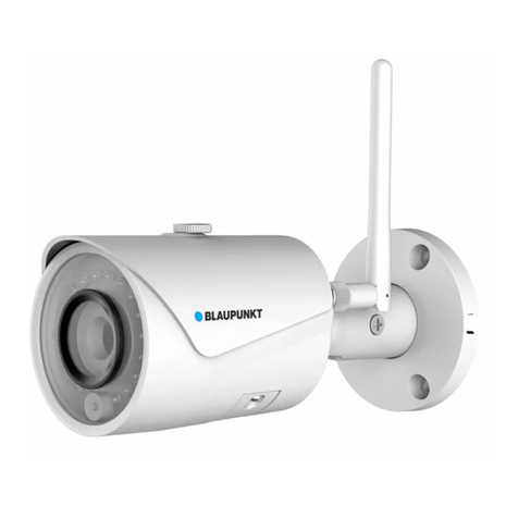
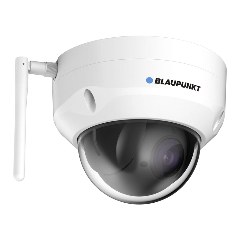
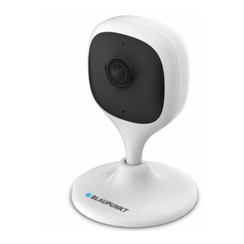
Blaupunkt VIO-D40 User manual

Home Security IP Camera
Enjoy it.
Quick Start Guide
IP Camera VIO-D40


EN Quick Start Guide
IP Camera VIO-D40
4
DE Schnellstart-Anleitung
IP Kamera VIO-D40
10
FR Mode d’emploi
Caméra IP VIO-D40
16
FI Käyttöopas
Sisäinen IP-kamera VIO-D40
34
ES Manual de usuario
Cámara IP para interiores VIO-D40
28
IT Manuale utente
Telecamera IP VIO-D40
22

4
English
1. Kit Content
VIO-40 IP Camera
English | Manual
Antenna
Power Supply EU type
3 wall screws / 3 plastic anchors Mounting map sticker
Quick Start Guide
NOTE:
•This manual is for reference only. Slight dierence may be found in the user
interface. All the designs and software here are subject to change without prior
written notice.
•All trademarks and registered trademarks mentioned are the properties of their
respective owners.

5
English
2. Product Description
1. Dome cover
2. Dome housing
3. Camera Power connector
4. Ethernet Network port
Indicator LED status: Camera status:
Red light on Camera booting up
Green light slow ashing Booting completed, waiting for WiFi
conguration
Green light quick ashing Wi smart conguration in progress.
Green light on Wi connection succeeded, operate normally.
Red and green lights ash
alternately
Camera rmware upgrade
Red light slow ashing Network connection failure or disconnected from
the network
Red light quick ashing Device malfunction, fail to boot up or SD card
malfunction. Please go to chapter 6“Help”.
5. Wireless antenna
6. Waterproof ring
7. Reset button
8. Micro SD card slot
9. Indicator light 1
10. Indicator light 2
NOTE:
This quickstart guide explains the installation and registration of the VIO camera. If
you want to learn more about the camera or the Cam4Home Plus app please check
chapter 6.
1
2
4
3
567
8
10
9

6
English
Download and install the“Cam4Home Plus”APP to
your smartphone from the App Stores.
3. Learn in a Camera
Connect your smartphone to your Wi-Fi network.
Step 1:
Step 2:
NOTE: If you are using a dual-band router, make sure that your smartphone is
connected to a 2.4 GHz WiFi Network and not to a 5GHz Wi Network. To learn
more about this please check your router manual.
Open the“Cam4Home Plus”APP. Create a user account by pressing the
“sign up”button located at the bottom left hand side.
To add a new camera tap the“+”button at the top right of the screen and
scan the QR code of the camera (refer to chapter 2 product description). Then follow the
instructions on the App to complete the camera registration.
Step 3:
Step 4:
NOTE: If you encounter any problem during the registration, check Chapter 5
Camera settings:
To access the camera settings go to the camera dasboard and tap the settings icon
at the top right.
4. Cam4Home Plus Management
Camera dashboard:
Tap on your camera under the main“device”menu. This will bring you to the camera
dashboard, where you can see the camera live stream video.
Push notications
On the device menu tap the 3 dot icon and select“Alarm Notications” .
Tap the“Alarm Notication”button to activate / deactivate the push notications.
NOTE: To receive push notications“Motion detection”must be enabled.
Important: Ensure that you have given permission to show pop up notications on your
smartphone permission settings.
Motion detection
To enable / disable motion detection go to: Camera dashboard --> Settings icon --> Arm
settings --> Motion detection. Note: Motion detection is enabled by default.
Video Storage
To storage video recordings the camera needs to have a Micro-SD card installed (see
chapter 5.1) or a Cloud Storage Plan activated.

7
English
5. Installation
•Check your WiFi signal strength and make sure that the WiFi signal is strong at
the location of your camera. For best performance, the smartphone needs to be
connected to a Wi-Fi network.
•Note: We recommend taking a picture of the label at the back of the camera. In case you
need to check the serial number, MAC address or QR-Code at a later stage.
Step 1:
5.1. Micro SD installation (optional)
•Locate the Micro SD-Card compartment of the D40. (refer to chapter 2 point )
•Slide the Micro-SD card slot to the OPEN position as displayed on the Micro-SD
card slot. After the Micro-SD card slot is in the open position open it and place the
Micro-SD card inside. Close the Micro-SD card slot and move it to the LOCK position
as displayed on the Micro-SD card slot.
8
NOTE: The Micro SD-Card is mandatory for local recording. Please make sure the
Micro SD-Card is CLASS10 rated. Supported are Micro SD-Cards from 8GB to 256GB .
Use the included hex wrench to open the dome cover by unfastening three
inner hex screws. (see below picture).
Take out the mounting map sticker and stick it on the ceiling or the wall.
Step 2:
Step 3:
5.2. Installation without mounting bracket
Find the desired installation location for the camera. Position the camera
where a power socket is in sucient proximity. Turn the camera ON and use the live
view image from the app to position the camera where everything to monitor is well in
view.
1. Antenna
2. U-shaped side exit
3. Rotational Bracket
4. LED Ring
5. Ceiling or Wall
6. Plastick Anchor
7. Dome Pedestal
8. Installation Screw
9. Dome Cover
10. Inner Hex Wrench
10
4
5
6
7
8
9
3
2
1

8
English
Drill through the 3 small marked points and install the plastic anchors on
the 3 small holes. Then choose one of the option bellow:
Step 5:
Adjust the dome camera according to the mounting map sticker and line
up the three screw holes in the dome pedestal to the three plastic anchors holes. Fix the
three screws in the three plastic anchors rmly.
Step 6:
Adjust the dome camera lens by moving the camera rotation bracket, and
check the position of the camera with the live image of the camera on your mobile
device. The camera rotation bracket can be moved manually by 355 degrees left to right
and 64 degrees up or down.To prevent that the LEDs on the LED ring get blocked by
the metal housing of the dome camera it is important to rotate the LED ring horizontal-
ly by 355 degrees and adjust the lens image to the desired position.
Note: When it rotates to 64° vertically, please pay attention to the image rotation direction to
avoid the outer cover blocking IR light and inuencing IR eect.
Step 7:
Use three Inner hex wrench screws to x the Dome housing on the pedestal.
Step 8:
5.3. Installation with mounting bracket (optional)
•The VIO-DMB1 mounting bracket is an optional accessory purchased separately from
the camera. If you desire to install the camera with the mounting bracket please refer
to the manual inside the mounting bracket box.
Connect the Camera Power connector to the included power supply cable.
Then connect the power supply cable to the power line socket. Optional: If you want
to install your camera via Ethernet cable, connect your camera to the router using an
Ethernet cable.
Step 9:
•If the ethernet network port and camera power connector need to exit from the back
of the camera through the installation surface, drill a hole according to the size of the
bigger hole on the mounting map sticker. (For the big hole ideally use a SDS-max
20mm drill)
•If the Ethernet Network port and Camera Power connector need to exit from the side
of the camera, the cable must go through the U-shape side exit on dome pedestal.
Use the mounting map sticker, to mark the position of the drilling points.
There are three holes for the screws and a big hole for the ethernet network port and
the camera power connector.
Step 4:
NOTE:
If due to special circumstances, such as a reinforced concrete wall, it’s not possible
to drill a hole of 20mm diameter, you have the option to cut o the thick Ethernet
Network port - see“Chapter 2. Product Appearance”, and seal it with a proper sealing
tape. With this option only a 12mm diameter drill is needed.
Alert: If you decide to cut o the Ethernet Port, you will lose the possibility to connect
the camera by Ethernet cable to a router or NVR. Additionally, you lose your right of
return.
9
English
6.5 Factory Reset
Plug in the camera and wait 1 minute until it boots up.
Step 1:
6. Help
If you experience any issue or have questions go to the FAQ in the app at:
“Me”menu -> Settings --> FAQ
For additional help, contact our technical support. To nd
your country customer support service, visit:
http://security.blaupunkt-service.com
6.1 FAQ
6.2 Cam4Home Plus Manual
6.3 How to Videos
If you want to learn more details of the Cam4Home Plus APP, download the Main APP
manual, with the following steps:
Visit: https://www.blaupunkt.com/service
1. On the 1st dropdown menu select your language
2. On the 2nd dropdown menu select“VIO-Series”
3. On the 3rd dropdown menu select “Manual”
4. Click“Submit”
5. Locate and click on“VIO-- Cam4Home Plus - Manual”
6.4 Customer Support and Returns
For“How-to-Videos”on the installation and registra-
tion please visit our youtube channel by scanning
the QR code. And then select your language from the
playlist.
Press the reset button (refer to chapter 2) for 15 seconds until the red Indi-
cator light turns on and starts ashing.
Wait until the green indicator light ashes slowly.
Now the camera is reverted to default settings.
Step 2:
Step 3:
Step 4:
1 2
3
4
Returns: If you wish to return your camera, we strongly advise that you rst delete
any camera paired to your account before sending the camera back.

10
Deutsch
1. Lieferumfang
VIO-D40 IP Kamera
Deutsch | Schnellstart-Anleitung
Antenne
Netzteil EU-Typ
3 Wandschrauben /
3 Kunststodübel
Montage-Schablone
Schnellstart-Anleitung
HINWEIS:
•Diese Schnellstart-Anleitung ist nur eine Ansatz. Es kann Abweichungen im
Vergleich zur tatsächlichen Benutzeroberäche geben. Alle Designs und die
Software können ohne Vorankündigung jederzeit geändert werden.
•Alle vorkommenden Markenzeichen und registrierten Marken sind Eigentum der
entsprechenden Eigentümer.

11
Deutsch
2. Geräteübersicht
1. Schutzabdeckung
2. Gehäuse
3. Kamera Stromanschluss
4. Ethernet-Netzwerkanschluss
LED-Statusanzeige: Kamerastatus:
Rote LED an Kamera wird hochgefahren
Grüne LED blinkt langsam Startvorgang abgeschlossen, Warten auf WLAN-
Konguration
Grüne LED blinkt schnell Smarte-WLAN-Konguration wird durchgeführt
Grüne LED an WLAN-Verbindung erfolgreich, normale
Funktionsweise.
Rote und grüne LED blinken
abwechselnd
Firmware-Aktualisierung der Kamera
Rote LED blinkt langsam Netzwerkverbindungsfehler oder Verbindung
zum Netzwerk getrennt
Rote LED blinkt schnell Gerätestörung, Startvorgang fehlgeschlagen
oder Fehlfunktion der SD-Karte. Bitte fahren Sie
mit Kapitel 6„Hilfe“ fort.
5. WLAN Antenne
6. Wasserdichter Ring
7. Reset-Taste
8. Micro SD-Kartenfach
9. Status LED 1
10. Status LED 2
HINWEIS:
Diese Schnellstart-Anleitung erklärt die Installation und Registrierung der VIO-
Kamera. Wenn Sie mehr über die Kamera oder die Cam4Home Plus-App erfahren
möchten, lesen Sie bitte Kapitel 6.
1
2
4
3
567
8
10
9

12
Deutsch
Laden Sie die„Cam4Home Plus“ App aus dem App
Store auf Ihr Smartphone herunter und installieren Sie diese.
3. Einlernen der Kamera
Verbinden Sie Ihr Smartphone mit Ihrem WLAN Netzwerk.
Schritt 1:
Schritt 2:
HINWEIS: Wenn Sie einen Dualband-Router verwenden, stellen Sie sicher, dass
Ihr Smartphone mit einem 2,4-GHz-WLAN-Netzwerk und nicht mit einem 5-GHz-
WLAN-Netzwerk verbunden ist. Um mehr darüber zu erfahren, lesen Sie bitte die
Anleitung Ihres Routers.
Önen Sie die„Cam4Home Plus“ App. Erstellen Sie ein Benutzerkonto,
indem Sie auf die Schaltäche“Registrieren”unten links klicken.
Um eine neue Kamera hinzuzufügen, tippen Sie auf die Schaltäche„+“
oben rechts auf dem Bildschirm und scannen Sie den QR-Code der Kamera (siehe
Kapitel 2 Produktbeschreibung). Folgen Sie dann den Anweisungen in der App, um die
Kamera-Registrierung abzuschließen.
Schritt 3:
Schritt 4:
HINWEIS: Wenn Sie während der Registrierung auf ein Problem stoßen,
lesen Sie Kapitel 5.
Kameraeinstellungen:
Um auf die Kameraeinstellungen zuzugreifen, gehen Sie zur Kamera-Übersicht
und tippen Sie auf das Einstellungssymbol oben rechts.
4. Cam4Home Plus App Funktionen
Kamera-Übersicht:
Wählen Sie nach dem Setup Ihre Kamera im“Geräte Menü”aus. Sie gelangen nun zur
Übersicht der Kamera, hier sehen Sie das Live-Stream-Video der Kamera.
Push-Benachrichtigungen:
Tippen Sie im“Geräte Menü”auf das Symbol und wählen Sie“Alarm-
benachrichtigungen” . Tippen Sie dann auf die Schaltäche“Alarm-
benachrichtigung”, um die Push-Benachrichtigungen zu aktivieren / deaktivieren.
HINWEIS: Um Push-Benachrichtigungen zu erhalten, muss“Bewegungserken-
nung”aktiviert sein.
Wichtig: Stellen Sie sicher, dass Sie der App die Berechtigung erteilen, Push-
Benachrichtigungen auf dem Startbildschirm anzuzeigen.
Bewegungserkennung:
Um die Bewegungserkennung zu aktivieren / gehen Sie zu: Kamera-Übersicht
-> Einstellungssymbol -> Bewegungserkennungs Einstellungen ->
Bewegungserkennung. Hinweis: Die Bewegungserkennung ist standardmäßig aktiviert.
Videospeicher:
Zum Speichern von Videoaufnahmen muss auf der Kamera eine Micro-SD-Karte (siehe
Kapitel 5.1) installiert oder ein Cloud-Speicherplan aktiviert sein.

13
Deutsch
Wählen Sie den gewünschten Installationsort für die Kamera aus. Position-
ieren Sie die Kamera so, dass sie den gewünschten Bereich überwachen kann. Bitte
denken Sie daran, dass sein Stromanschluss in Reichweite des Kabels vorhanden sein
muss. Überprüfen Sie die Signalstärke des WLAN-Netzes, am Installationsort und
überprüfen Sie den Bildausschnitt in der„Live Überwachung“.
5. Installation
•Überprüfen Sie die Stärke Ihres WLAN-Signals und stellen Sie sicher, dass das WLAN
Signal am Standort Ihrer Kamera stark genug ist. Für eine optimale Bildübertragung
muss das Smartphone mit einem WLAN-Netzwerk verbunden sein.
•Hinweis: Wir empfehlen, das Etikett auf der Rückseite der Kamera zu fotograeren. Falls
Sie zu einem späteren Zeitpunkt die Seriennummer, MAC-Adresse oder den QR-Code
überprüfen müssen.
Schritt 1:
5.1. Installation der Micro-SD-Karte (optional)
•Suchen Sie das Micro SD-Kartenfach der D40. (siehe Kapitel 2 Punkt )
•Um eine SD-Karte einzusetzen (nicht mitgeliefert) ist es erforderlich, den Kartenhalter
zunächst in die“OPEN”Position zu schieben wie auf dem Micro-SD-Halter abgebildet.
Nach dem Einsetzen der Karte diesen wieder in die“LOCK”Position schieben. Jetzt ist
die Micro-SD-Karte installiert und kann verwendet werden.
8
HINWEIS: Die Micro-SD-Karte ist für die lokale Aufzeichnung von Videoereignissen-
notwendig.Vergewissern Sie sich, dass die Micro SD-Karte CLASS10-zertiziert ist.
Unterstützt werden Micro-SD-Karten von 8 GB bis 256 GB.
Verwenden Sie den mitgelieferten Inbusschlüssel, um das Dome-Gehäuse
zu önen, indem Sie die drei Innensechskantschrauben lösen. (siehe Bild unten).
Schritt 2:
5.2. Montage ohne Wandhalterung (VIO-DMB1)
1. Antenne
2. Aussparung für Kabel
3. Drehhalterung
4. LED-Ring
5. Decke oder Wand
6. Kunststodübel
7. Kamerafuß
8. Schrauben
9. Dome-Gehäuse
10. Inbusschlüssel
Nehmen Sie die Montage-Schablone heraus und kleben Sie diese an die
Decke oder an die Wand.
Schritt 3:
10
4
5
6
7
8
9
3
2
1

14
Deutsch
Bohren Sie durch die 3 kleinen markierten Punkte und bringen Sie die Kunst-
stodübel an den 3 kleinen Löchern an. Wählen Sie dann eine der folgenden Optionen:
Schritt 5:
Richten Sie die Domekamera gemäß der Montage-Schablone aus und richt-
en Sie die drei Schraubenlöcher im Kamerafuß an den drei Bohrlöchern der Kunststo-
dübel aus. Befestigen Sie nun die drei Schrauben in den drei Kunststodübeln.
Schritt 6:
Stellen Sie das Domekameraobjektiv durch Bewegen der Drehhalterung ein
und überprüfen Sie die Position der Kamera anhand des Livebilds der Kamera auf Ihrem
Smartphone. Die Drehhalterung kann manuell um 355 Grad von links nach rechts und
64 Grad nach oben oder unten bewegt werden. Um zu verhindern, dass die LEDs am
LED-Ring vom Metallgehäuse der Dome-Kamera blockiert werden, ist es wichtig, den
LED-Ring horizontal um 355 Grad zu drehen und das Objektivbild in die gewünschte
Position zu bringen.
Hinweis: Achten Sie bei einer vertikalen Drehung von 64 ° auf die Bilddrehrichtung, um zu
vermeiden, dass die äußere Abdeckung das IR-Licht blockiert und den IR-Eekt beeinusst.
Schritt 7:
Befestigen Sie das Dome-Gehäuse mit den drei Innensechskantschrauben
am Kamerafuß.
Schritt 8:
5.3. Montage mit Wandhalterung (optional)
•Die VIO-DMB1-Montagehalterung ist ein optionales Zubehör, das separat von der
Kamera erhältlich ist. Wenn Sie die Kamera mit der Montagehalterung installieren
möchten, lesen Sie bitte die Anleitung im Lieferumfang der Montagehalterung.
Schließen Sie den Kamera-Stromanschluss an das mitgelieferte Netzteil
an. Schließen Sie dann das Stromkabel an die Steckdose an. Optional: Wenn Sie Ihre
Kamera über ein Ethernet-Kabel installieren möchten, schließen Sie Ihre Kamera mit
einem Ethernet-Kabel an den Router an.
Schritt 9:
•Wenn der Ethernet-Netzwerkanschluss und der Kamera-Stromanschluss auf der
Rückseite der Kamera durch die Decke oder Wand geführt werden sollen, bohren Sie
ein Loch, das der Größe des größeren Lochs auf der Montage-Schablone entspricht.
(Verwenden Sie für das große Loch idealerweise einen SDS-max 20-mm-Bohrer.)
•Wenn der Ethernet-Netzwerkanschluss und der Kamera-Stromanschluss an der Seite
der Kamera herausgeführt werden müssen, muss das Kabel durch die U-förmige
Aussparung am seitlichen Ausgang des Kamerafuß geführt werden.
Verwenden Sie die Montage-Schablone, um die Position der Bohrpunkte zu
markieren. Es gibt drei Löcher für die Schrauben und ein großes Loch für den Ether-
net-Netzwerkanschluss und den Kamera-Stromanschluss.
Schritt 4:
HINWEIS:
Wenn aufgrund besonderer Umstände, wie z. B. einer Stahlbetonwand, kein Loch mit
einem Durchmesser von 20 mm gebohrt werden kann, haben Sie die Möglichkeit,
den dicken Ethernet-Netzwerkanschluss“siehe Kapitel 2”abzuschneiden und ver-
siegeln Sie es mit einem geeigneten Dichtungsband. Mit dieser Option wird nur ein
Bohrer mit 12 mm Durchmesser benötigt. Warnung: Wenn Sie den Ethernet-Netzw-
erkanschluss abschneiden, verlieren Sie die Möglichkeit, die Kamera über ein Ether-
net-Kabel an einen Router oder einen NVR anzuschließen. Außerdem verlieren Sie Ihr
Rückgaberecht.

15
Deutsch
6.5 Zurücksetzen auf Werkseinstellungen
Schließen Sie die Kamera an und warten Sie 1 Minute, bis sie hochfährt.
Schritt 1:
6. Hilfe
Wenn Sie Probleme oder Fragen haben, lesen Sie die FAQ in der App unter:
“Ich”Menü -> Einstellungen --> FAQ
Weitere Hilfe erhalten Sie von unserem technischen
Support. Um den Kundendienst Ihres Landes zu nden,
besuchen Sie: http://security.blaupunkt-service.com
6.1 FAQ
6.2 Cam4Home Plus Anleitung
6.3 How to Videos
Wenn Sie mehr über die Cam4Home Plus-App erfahren möchten, laden Sie die Anlei-
tung der Cam4Home Plus-App mit den folgenden Schritten herunter:
Besuchen Sie: https://www.blaupunkt.com/service
1. Wählen Sie im 1.Dropdown-Menü Ihre Sprache aus
2. Wählen Sie im 2.Dropdown-Menü“VIO-Series”
3. Wählen Sie im 3. Dropdown-Menü“Manual”.
4. Klicken Sie auf“Submit”.
5. Klicken Sie nun auf“VIO-- Cam4Home Plus - Manual”
6.4 Kundenservice & Rücksendung
Für“How-to-Videos”zur Installation und Registrierung
besuchen Sie bitte unserenYoutube-Kanal, indem Sie
den QR-Code scannen. Wählen Sie anschließend Ihre
Sprache aus der Wiedergabeliste aus.
Drücken Sie die Reset-Taste (siehe Kapitel 2) 15 Sekunden lang, bis die rote
Status LED aueuchtet und zu blinken beginnt.
Warten Sie, bis die grüne Status LED langsam blinkt.
Jetzt wird die Kamera auf die Werkseinstellungen zurückgesetzt.
Schritt 2:
Schritt 3:
Schritt 4:
1 2
3
4
Rückgabe: Falls Sie Ihre Kamera zurückgeben möchten, empfehlen wir dringend,
dass Sie zuerst alle mit Ihrem Konto verknüpften Kameras löschen, bevor Sie die
Kamera zurücksenden.

16
Français
1. Contenu de la boîte
Camera IP VIO-D40
Français | Guide rapide
Antenne
Adaptateur secteur de type EU
3 vis / 3 chevilles plastique Gabarit autocollant de montage
Ce guide
NOTE :
•Ce manuel est pour votre référence uniquement, des di érences peuvent
apparaître dans l’interface utilisateur. Les designs et interfaces sont susceptibles
d’être modiés sans préavis.
•Toutes les marques citées sont la propriété de leurs dépositaires respectifs.

17
Français
2. Product Description
1. Capot du dôme
2. Corps du dôme
3. Câble d’alimentation
4. Port réseau Ethernet
Etat du voyant : Etat de la caméra :
Rouge xe La caméra démarre
Vert, clignotant lentement Démarrage terminé, attente de la conguration
WiFi
Vert, clignotant rapidement Conguration WiFi en cours
Vert xe Connexion WiFi OK, fonctionnement normal
Rouge et Vert, clignotants
alternativement
Mise à jour du Firmware de la caméra
Rouge, clignotant lentement Connexion réseau échouée ou déconnexion du
réseau
Rouge, clignotant rapidement Défaillance système, ou carte SD. Pour de l’aide,
voir le chapitre 6“Aide”.
5. Antenne
6. Joint d’étanchéïté
7. Bouton Reset
8. Emplacement Micro SD
9. Voyant 1
10. Voyant 2
NOTE :
Ce guide rapide explique l’installation et l’enregistrement de la caméra. Si vous voulez
en apprendre d’avantage sur celle-ci ou l’application Cam4Home, veuillez vous
rendre au chapitre 6.
1
2
4
3
567
8
10
9

18
Français
Téléchargez et installez l’app“Cam4Home Plus”sur
votre smartphone depuis votre magasin d’applications
3. Enregistrer une caméra
Connectez votre téléphone à votre réseau WiFi.
Etape 1
Etape 2
NOTE : Si vous utilisez un routeur dual-band, vériez que votre smartphone est
connecté au réseau 2.4 Ghz et non sur celui de 5Ghz. Pour en apprendre plus,
rendez-vous sur le manuel de votre routeur.
Ouvrez l’app“Cam4Home Plus”. Créez un compte utilisateur en appuyant
sur le bouton“s’inscrire”situé en bas à gauche du bouton“Connectez-vous”.
Pour ajouter la caméra, appuyez sur le bouton“+”en haut à droite. Suivez
ensuite les instructions de l’application pour terminer l’enregistrement de la caméra.
Etape 3
Etape 4
NOTE : Si un problème survient durant l’enregistrement, allez au chapitre 5.
Réglages caméra :
Pour accéder aux réglages de la camera, allez dans son tableau de bord et appuyez sur
l’icone réglages en haut à droite.
4. Gestion de Cam4Home Plus
Tableau de bord caméra :
Après la conguration, sélectionnez votre caméra dans le menu“Mon appareil”, cela
vous emmenera sur son tableau de bord, où vous pourrez voir sa vidéo en direct.
Notications push :
Dans le menu du périphérique, appuyez sur l’icone et sélectionnez “Notications
d’alarme” . Appuyez sur “Notications d’alarme”pour les activer/désactiver.
NOTE : Pour recevoir les notications, la détection de mouvement doit être active.
Important : Assurez-vous que vous avez donné la permission à l’application d’acher
des notications sur le téléphone.
Détection de mouvement :
Pour activer/désactiver ce paramètre : Tableau de bord Caméra --> --> Réglages
Armement --> Détection de mouvements. Cette option est activée par défaut.

19
Français
5. Installation
•Vériez la force de votre signal WiFi, et assurez-vous qu’il soit fort à l’endroit de votre
caméra. Pour de meilleures performances, votre smartphone doit être connecté àun
réseau WiFi .
•Note : Nous recommandons de prendre une photo de l’étiquette située en dessous de la
caméra, an d’accèder au numéro de série, l’adresse MAC ou au QR Code plus tard.
Etape 1
5.1. Installation de la carte Micro SD (facultatif)
•Cherchez le compartiment Micro SD de la caméra D40. (voir chapitre 2 point )
•Glissez l’emplacement sur la position OPEN comme indiqué sur celui-ci. Ouvrez
l’emplacement et placez la carte Micro SD à l’intérieur. Fermez l’emplacement Micro
SD et glissez le en position LOCK comme indiqué sur celui-ci.
8
NOTE : Une carte Micro SD est obligatoire pour l’enregistrement en local.
Assurez-vous que la carte soit de Class 10 au minimum et de 8GB à 256GB
Utilisez la clé héxagonale fournie pour ouvrir le capot du dôme en devissant
les vis à tête hexagonales intérieures. (see below picture).
Collez le gabarit de montage à l’endroit d’installation désiré.
Etape 2
Etape 3
5.2. Installation sans le support de montage
Installez la caméra à proximité d’une prise électrique. Allumez la caméra,
et utilisez la vue en direct de l’application pour positionner la caméra sur l’endroit que
vous souhaitez surveiller (contrôlez le champ de vision de la caméra).
1. Antenne
2. Sortie latérale
3. Support rotatif
4. Anneau lumineux IR
5. Mur ou plafond
6. Cheville plastique
7. Base du dôme
8. Vis d’installation
9. Capot du dôme
10. Clé héxagonale
10
4
5
6
7
8
9
3
2
1

20
Français
Percez les 3 trous que vous avez marqués et installez les chevilles plastiques
Ensuite, choisissez une des options ci-dessous :
Etape 5
Ajustez la caméra selon le gabarit de montage, et alignez les 3 futs de vis
présents dans la base du dôme avec les 3 chevilles plastiques installées dans le mur.
Insérez les vis dans les futs puis serrez-les au maximum dans les chevilles.
Etape 6
Ajustez l’objectif de la caméra en bougeant le support rotatif, et vériez
la position de la caméra avec la vidéo en direct depuis votre smartphone. Le support
rotatif peut être manipulé sur 355° de gauche à droite et de 64° de haut en bas. Pour
empêcher que les LEDs sur l’anneau lumineux IR ne soient bloquées par le capot
métallique du dôme, il est important de bouger l’anneau de 355° et ensuite d’ajuster
l’image de l’objectif sur la position désirée.
Note : Lorsque vous bougerez de haut en bas le support rotatif, veuillez faire attention à
éviter que le capot extérieur ne bloque ou renvoie la lumière infrarouge de l’anneau IR.
Etape 7
Utilisez les 3 vis à tête hexagonale pour xer le dôme sur sa base.
Etape 8
5.3. Installation avec support de montage facultatif
•Le support VIO-DMB1 est un accessoire additionnel à acheter séparément de la
caméra. Si vous désirez installer la caméra avec ce support, veuillez vous référer au
manuel dans la boite du support VIO-DMB1.
Branchez le connecteur d’alimentation de la caméra sur le câble d’alimen-
tation fourni. Puis branchez le cable d’alimentation sur une prise murale. Facultatif : Si
vous souhaitez utiliser votre caméra via le câble Ethernet, connectez un câble entre
votre routeur et le connecteur Ethernet de la caméra.
Etape 9
•Si le port Ethernet et le connecteur d’alimentation de la caméra ont besoin de sortir
depuis l’arrière de celle-ci, percez un trou de 20mm à l’endroit indiqué sur le gabarit
de montage.
•Si le port Ethernet et le connecteur d’alimentation de la caméra ont besoin de sortir
sur le côté de la caméra, passez-les par la sortie latérale de la base du dôme.
Utilisez le gabarit pour marquer la position des trous à percer. Il y a 3 trous
pour les vis d’installation et un trou plus grand pour le passage des cables comprenant
le port Ethernet et le connecteur d’alimentation.
Etape 4
Table of contents
Languages:
Other Blaupunkt Security Camera manuals

Blaupunkt
Blaupunkt IRC-S2 User manual

Blaupunkt
Blaupunkt VIO-HS20 User manual

Blaupunkt
Blaupunkt VIO-DP20 User manual

Blaupunkt
Blaupunkt HOS-X20 User manual

Blaupunkt
Blaupunkt VIO-B10 User manual

Blaupunkt
Blaupunkt VIO-DP20 User manual

Blaupunkt
Blaupunkt VIO-B40 User manual

Blaupunkt
Blaupunkt VIO-DP20 User manual