EN | 2D8125MUX | Installation and Operation Guide | 1.0
2 Bosch Security Systems, Inc. | 12/15 | F01U034973-03
Contents
1.0 Introduction............................................... 3
1.1 Description...................................................... 3
1.2 Listings............................................................3
1.3 Specifications.................................................. 3
2.0 Operation .................................................. 4
3.0 Installation................................................. 4
3.1 Installing the enclosure................................... 4
3.2 Wiring to the control panel ............................. 5
3.2.1 Disconnecting the Battery and Transformer ...5
3.2.2 Wiring Procedure ............................................5
4.0 Program Multiplex Bus Points .................... 6
4.1 Connecting the D5060 Programmer ...............6
4.2 Programming................................................... 8
4.2.1 Powering the D5060 .......................................8
4.2.2 Programming Points........................................ 8
4.2.3 Removing a Point from the D8125MUX........... 8
4.2.4 Interrogation Mode .........................................9
4.3 Wiring the D8125MUX to Multiplex Points......9
4.4 Using Power B and MUX BUS B (Optional)...10
4.5 Wiring Multiplex Devices to the Multiplex Bus
...................................................................... 10
4.6 Installing a Multiplex Device .........................11
4.6.1 Adding Multiplex Devices to the Control Panel
...................................................................... 11
4.6.2 Removing Multiplex Devices from the Control
Panel .............................................................11
4.7 Point Matrix Tables ....................................... 13
4.8 Single Input Multiplex Devices......................21
4.9 MX250 Photoelectric Smoke Detectors and
MXB2W Base or D7050 Photoelectric Smoke
Detector and D7050-B6 Base........................21
4.10 DS7460(i) Dual Input Multiplex Module .......22
4.11 DS7432 Eight Input Remote Module.............22
4.12 DS7465(i) Input/Output Module................... 23
5.0 Testing the System................................... 24
5.1 Local Walk Test (Command 44)....................24
5.2 Missing Multiplex Points ............................... 24
5.3 Extra Multiplex Points ...................................24
5.4 Ground Fault Notification on Multiplex Devices
...................................................................... 24
6.0 Troubleshooting....................................... 25
Figures
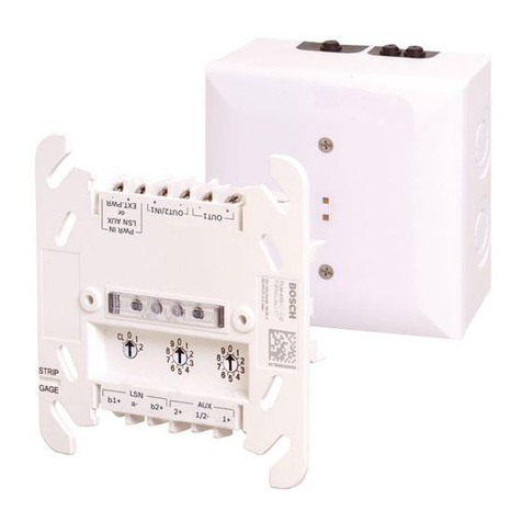
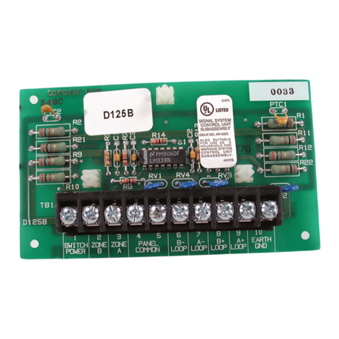
Figure 1: D8125MUX Multiplex Bus Interface Module
..................................................................4
Figure 2: Installation diagram ..................................4
Figure 3: D8125MUX Wiring Diagram ......................5
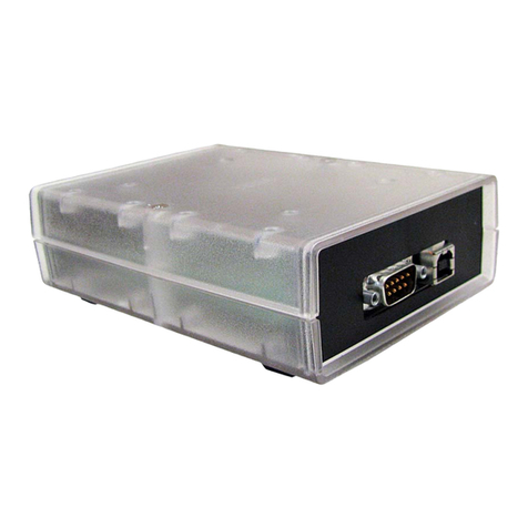
Figure 4: D5060 Multiplex Point Programmer..............6
Figure 5: Installing Multiplex Points without DIP
Switches Wiring Diagram..........................7
Figure 6: Installing Multiplex Points with DIP
Switches Wiring Diagram..........................7
Figure 7: Programmer Cables (included) ................7
Figure 8: Wiring the D8125MUX to Detection
Systems Multiplex Points .........................9
Figure 9: Wiring Multiplex Devices to MUX Bus.....10
Tables
Table 1: Specifications ...........................................3
Table 2: Operation LED Descriptions.....................4
Table 3: D5060 LED Definitions ................................6
Table 4: Point Type Entry Code..............................8
Table 5: D8125MUX Line Length ..........................10
Table 6: Control Panel to D8125MUX Distance....10
Table 7: Multiplex Devices....................................11
Table 8: Point Conversion Table...........................12
Table 9: DS7457i, DS7461i, and DS7465i Switch
Settings When Using D8125MUX on
ZONEX 1 .................................................14
Table 10: DS7457i, DS7461i, and DS7465i Switch
Settings When Using D8125MUX on
ZONEX 2 .................................................17
Table 11: DS7460i Switch Settings When Using
D8125MUX..............................................19
Table 12: Single Input Multiplex Device Point
Response Configuration .........................21
Table 13: MX250, MX250TH, D7050, and D7050TH
Point Type Configuration........................21
Table 14: DS7460(i) Point Type Configuration ......22
Table 15: DIP Switch Settings................................22
Table 16: DS7432 Point Type Configuration ..........23
Table 17: DS7465(i) Point Type Configuration ......23
Table 18: Troubleshooting......................................25
