4BA-166
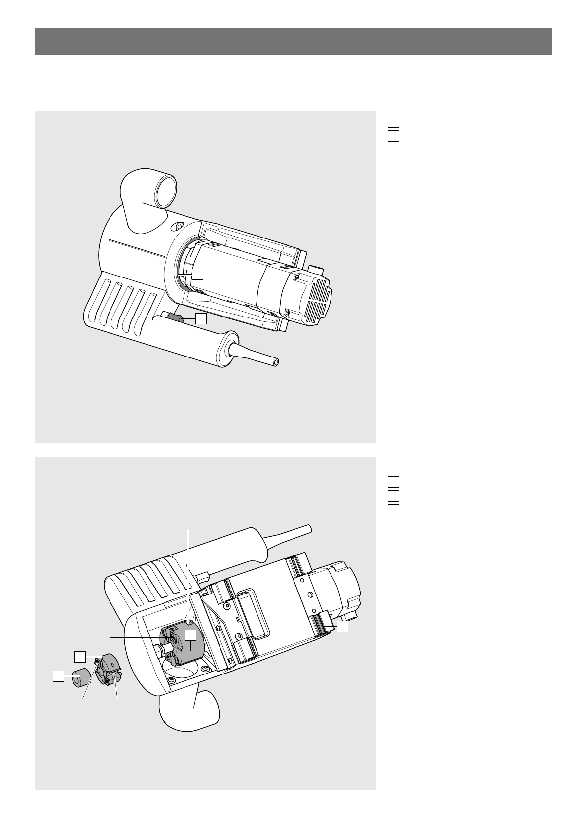
M35.7200.NA – Bottom router
NOTE
■The NOTE sign indicates information that should be observed.
Risk levels WARNING
■WARNING indicates a danger that could lead to serious injury if not avoided.
CAUTION
■CAUTION indicates a danger that could lead to injury if not avoided.
WARNING
WARNING
Serious cuts.
Failure to heed this warning may result in personal
injury.
➢Only push the carriage by the handle.
Serious cuts.
Failure to heed this warning may result in personal injury.
➢The bottom router must be disconnected from the pow-
er supply before set-up, cleaning and maintenance.
➢The bottom router is only intended for use by one person.
➢KEEP CHILDREN AWAY. All visitors should be kept safe distance from work area.
➢MAKE WORKSHOP KID PROOF with padlocks, master switches,
or by removing starter keys.
➢WEAR PROPER APPAREL. Do not wear clothing, gloves, neckties, rings,
bracelets, or other jewelry which may get cought in moving parts. Nonslip
footwear is recommended. Wear protective hair covering to contain long hair.
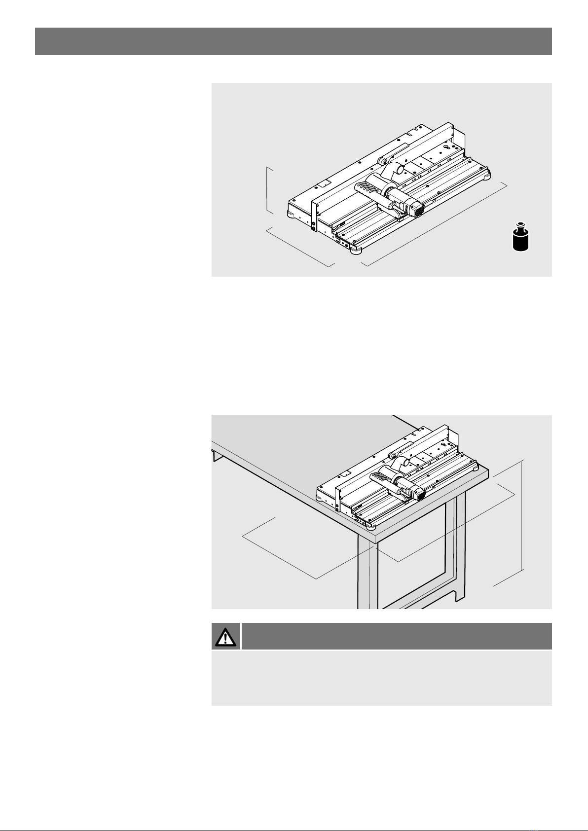
➢Only attach the bottom router to a sufficiently stable table.
➢Operate with the bottom router only when the router carriage [S1] is mounted
➢Ensure there is sufficient lighting.
➢Only operate the bottom router with the dust extraction system on.
➢Before starting work, you should check that the protection devices and
mechanical parts are functioning properly. Any damaged parts should be
replaced by original parts from Blum.
➢Do not make any changes or alterations to the bottom router.
➢For your own safety, use only those accessories which are recommended or
specified in the instruction manual or Blum sales catalog.
➢Check the electrical cable for damage.
WARNING