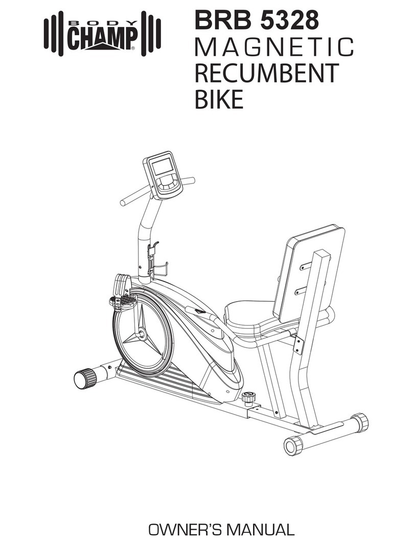
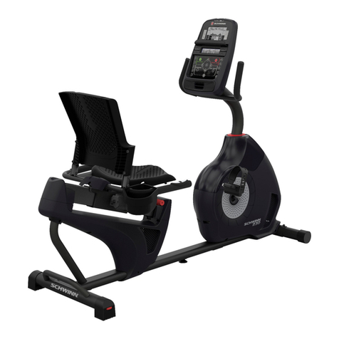
Body Champ BRB 3800 User manual

BRB 3800
MAGNETIC
RECUMBENT
BIKE
OWNER’S MANUAL
* This item is for consumer use only and it is not meant for commercial use.

This page intentionally left blank

General Information
Page 1
Warranty
Body Flex Sports warrants your product for
a period of 1 year for the frame and 90 days
on all parts if the item is used for the intended
purpose, properly maintained and not used
commercially. Any alterations or incorrect
assembly of the product will void this warranty.
Proof of purchase must be presented for any
warranty validation (no exceptions). This
warranty applies to the original purchaser only
and is not transferable.
This warranty does not cover abuse or defects
caused during use, storage or assembly.
During the warranty period, Body Flex Sports
reserves the right to:
a). provide replacement parts to the
purchaser in an effort to repair the item.
b). repair the product returned to our
warehouse (at the purchaser’s cost).
c). replace the product if neither of the two
previously mentioned actions effect repair.
This warranty does not cover normal wear and
tear on upholstery.
Questions
If you have any questions concerning the
assembly of your item or if any parts are
missing, please DO NOT RETURN THE
ITEM TO THE STORE OR CONTACT THE
RETAILER. Our dedicated customer service
staff can help you with any questions you may
have regarding the assembly of this unit and
can also mail you replacement parts.
Customer Support
Customer Support is open 9:00 a.m. to 5:00
p.m. (Pacic Time) Monday through Friday.
Please contact us by any of the following
means.
Body Flex Sports, Inc.
21717 Ferrero Parkway, Walnut, CA 91789
Telephone: (888) 266 - 6789
Fax: (909) 598 - 6707
Email: info@bodyexsports.com
Safety
Before you undertake any exercise program,
please be sure to consult with your doctor.
Frequent strenuous exercise should be
approved by your doctor and proper use
of your product is essential. Please read
this manual carefully before commencing
the assembly of your product or starting to
exercise.
• Please keep all children away from this item
when in use. Do not allow children to climb or
play on them when they are not in use.
• Supervise teenagers while they use this unit.
• For your own safety, always ensure that there
is at least 3 feet of free space in all directions
around your product while you are exercising.
• Regularly check to see that all nuts, bolts and
ttings are securely tightened. Periodically
check all moving parts for obvious signs of
wear or damage.
• Clean only with a damp cloth, do not use
solvent cleaners. If you are in any doubt, do
not use your product; contact CUSTOMER
SUPPORT.
• Before use, always ensure that your product
is positioned on a solid, at surface. If
necessary, use a rubber mat underneath to
reduce the possibility of slipping.
• Always wear appropriate clothing and
footwear such as training shoes when
exercising. Do not wear loose clothing that
could become caught in moving parts during
exercise.
• Do not use this unit if it is not functioning
properly or if it is not fully assembled.
• Do not use this unit for commercial purposes.
Storage and Use
Your product is intended for use in clean
dry conditions. You should avoid storage in
excessively cold or damp places as this may
lead to corrosion and other related problems.
Weight Limit
Your product is suitable for users weighing:
250 pounds or less.
BRB 3800

Hardware & Tool List
The following hardware is used to assemble your unit. Please take a moment to familiarize yourself with these
items. Please note some of this hardware is already pre-assembled on the machine. Do not be alarmed if you
see parts on this page that are not included in your hardware packet
#12. Carriage Bolt (M8x70 mm)
[4 Pieces]
#16. Hex Bolt (M8x65 mm)
[2 Pieces]
#13. Hex Bolt (M10x70 mm)
[6 Pieces]
#14. Hex Bolt (M10x65 mm)
[1 Piece]
#15. Hex Bolt (M10x45 mm)
[2 Pieces]
#17. Screw (M8x20 mm)
[10 Pieces]
Pre-assemble [4 Pieces]
#18. Screw (M5x12 mm)
[4 Pieces]
Pre-assemble
#20. Screw (M5x8 mm)
[2 Pieces]
Washer
#23. Washer (M10)
[4 Pieces]
#24. Washer (M8)
[8 Pieces]
Pre-assemble [2 Pieces]
#22. Arc Washer (M8)
[8 Pieces]
Pre-assemble [2 Pieces]
#21. Spring Washer (M8)
[10 Pieces]
Pre-assemble [4 Pieces]
Nut
#25. Nylon Nut (M10)
[9 Pieces]
#26. Nut (M8)
[4 Pieces]
Tool
#53. Tool 1
[2 Pieces]
#54. Tool 2 (5 mm)
[1 Pieces]
Bolt
BRB 3800 Page 2

Parts Listing
The following parts list describes all of the parts illustrated on the
exploded diagram on the following page. Please note, most of
these parts are already pre-assembled on your unit.
BRB 3800 Page 3
Part# Description Part# Description
01 Main Frame 28 Knob Bolt (M8x25 mm)
02 Bottom Frame 29 End Cap for Rear Stabilizer
03 Backrest Cushion Frame 30
A
djustable End Cap for Front Stabilize
r
04 Seat Cushion Frame 31 Square Inner Cap (50x50x1.5t)
05 Seat Cushion Support Frame 32 Round Inner Cap (25x1.5t)
06 Right Rear Handle Bar 33 Main Frame Sleeve
07 Left Rear Handle Bar 34 Bottom Frame Sleeve
08 Front Handle Bar 35 Foam Grip
09 Front Post 36 Foam Grip
10 Front Stabilizer 37 Right Pedal
11 Rear Stabilizer 38 Left Pedal
12 Carriage Bolt (M8x70 mm) 39 Crank
13 Hex Bolt (M10x70 mm) 40 Handle Pulse
14 Hex Bolt (M10x65 mm) 41 Sensor Wire 1
15 Hex Bolt (M10x45 mm) 42 Sensor Wire 2
16 Hex Bolt (M8x65 mm) 43 Sensor Wire 3
17 Screw (M8x20 mm) 44 Sensor Wire 4
18 Screw (M5x12 mm) 45 Sensor Wire 5
19 Screw (M4x20 mm) 46 Sensor Wire 6
20 Screw (M5x8 mm) 47 Sensor Wire 7
21 Spring Washer (M8) 48 Tension Control
22 Arc Washer (M8) 49 Tension Control Cable
23 Washer (M10) 50 Monitor
24 Washer (M8) 51 Seat Cushion
25 Nylon Nut (M10) 52 Backrest Cushion
26 Nut (M8) 53 Tool 1
27 Spring Loaded Knob (M16x30 mm) 54 Tool 2

Exploded Diagram
The following diagram is provided to help you familiarize yourself with the parts and
hardware that will be used during the assembly process. Please note that not all of the
parts and hardware you see here will be used while you are assembling the machine
because some of these items are already pre-installed. Please continue to the next
page to begin the assembly process and use this page only as a reference guide for
parts and hardware.
BRB 3800 Page 4

BRB 3800
Assembly Step 1
Page 5
Hardware Required
A
B
C
A.) Stabilizer Assembly
Align the Front Stabilizer (#10) to the Main Frame (#01). Attach
them together by inserting two Carriage Bolts (#12) through the
Front Stabilizer (#10) followed by the Main Frame (#01). Secure
them together using two Arc Washers (#22), two Spring Washers
(#21) and two Nuts (#26).
Please Note that the Front Stabilizer (#10) is the one with end
caps that spin.
B.) Stabilizer Assembly
Align the Rear Stabilizer (#11) to the Bottom Frame (#02). Attach
them together by inserting two Carriage Bolts (#12) through the
Rear Stabilizer (#11) followed by the Bottom Frame (#02). Secure
them together using two Arc Washers (#22), two Spring Washers
(#21) and two Nuts (#26).
C.) Frame Assembly
Connect Sensor Wire 3 (#43) to Sensor Wire 4 (#44). Pull up the
Spring Loaded Knob (#27) and slide the Bottom Frame (#02)
into the Main Frame (#01). Slide the Bottom Frame (#02) further
into the Main Frame (#01) for shorter users and further out for
taller users. Once you select the desired setting, screw the Spring
Loaded Knob (#27) into the Main Frame (#01) and through the
Bottom Frame (#02) to secure it in place. Tighten them using two
Screws (#20).
#12. Carriage Bolt (M8x70 mm)
[4 Pieces]
#20. Screw (M5x8 mm)
[2 Pieces]
Washer
#22. Arc Washer (M8)
[4 Pieces]
#21. Spring Washer (M8)
[4 Pieces]
Nut
#26. Nut (M8)
[4 Pieces]
Bolt
Assembly Instructions

#34 Bolt (M8x15 mm)
[8 Pieces] #36 Bolt (M8x45 mm)
[1 Piece]
#38 Bolt (M8x55 mm)
[2 Pieces] #40 Bolt (M8x70 mm)
[2 Pieces]
#33 Nut (M8)
[5 Pieces]
#37 Washer (M8) [18 Pieces]
6 mm [1 Piece] S13-14-15-φ5 [1 Piece]
BOLT
NUT
WASHER
TOOL
#34 Bolt (M8x15 mm)
[8 Pieces] #36 Bolt (M8x45 mm)
[1 Piece]
#38 Bolt (M8x55 mm)
[2 Pieces] #40 Bolt (M8x70 mm)
[2 Pieces]
#33 Nut (M8)
[5 Pieces]
#37 Washer (M8) [18 Pieces]
6 mm [1 Piece] S13-14-15-φ5 [1 Piece]
BOLT
NUT
WASHER
TOOL
BRB 3800
A.) Pre-Assembled Hardware Removal
Remove the four Screws (#17), four Spring Washers (#21), two
Arc Washers (#22), two Washers (#24) that are pre-assembled
on the top of the Main Frame (#01) and set them aside.
B.) Tension Controller Installation
With the help of an assistant, connect the Sensor Wire 4 (#44) to
Sensor Wire 5 (#45) and Sensor Wire 6 (#46) to Sensor Wire 7
(#47). Please refer to the illustrated diagram on the bottom and
assemble the Tension Control (#48).
C.) Center Post Assembly
Once the Tension Control (#48) is properly installed, carefully slide
the Front Post (#09) in to the Main Frame (#01) with the tension
knob control on the right hand side. Secure both sides of the Front
Post (#09) using a two Washers (#24), two Spring Washers (#21)
and two Screws (#17) that were previously removed. Please refer
to the illustrated diagram below. Secure the front of the Front Post
(#09) to the Main Frame (#01) using two Arc Washers (#22), two
Spring Washers (#21) and two Screws (#17) that were previously
removed.
TENSION WIRE ASSEMBLY
Insert the tip of the Tension Control (#48) wire into the Tension
Control Cable (#49) head at an angle. Tilt the Tension Control
(#48) wire into the crevice and then pull upward.
SENSOR WIRE ASSEMBLY
Assembly Instructions
Assembly Step 2
Page 6
Hardware Required
#17. Screw (M8x20 mm)
[4 Pieces]
Washer
#24. Washer (M8)
[2 Pieces]
#22. Arc Washer (M8)
[2 Pieces]
#21. Spring Washer (M8)
[4 Pieces]
Bolt

BRB 3800
Assembly Step 3
Page 7
Hardware Required
A.) Backrest Cushion Frame Assembly
Connect Sensor Wire 2 (#42) to Sensor Wire 3 (#43). Insert
two Hex Bolts (#15) through two Washers (#23) followed by
the Bottom Frame (#02) and Backrest Cushion Frame (#03).
Secure them together using two Nylon Nuts (#25).
B.) Seat Cushion Frame Assembly
1. Align and attach the Seat Cushion Support Frame (#05) to
the Bottom Frame (#02). Insert a Hex Bolt (#14) through a
Washer (#23) followed by the Bottom Frame (#02) and the
Seat Cushion Support Frame (#05). Secure them together
using a Washers (#23) and a Nylon Nut (#25).
2. Connect Sensor Wire 1 (#41) to Sensor Wire 2 (#42). Insert
two Hex Bolts (#13) through the Seat Cushion Frame (#04)
and the Backrest Cushion Frame (#03), then secure them
together using two Nylon Nuts (#25).
3. Insert two Hex Bolts (#13) through the Seat Cuhion Support
Frame (#05) and the Seat Cushion Frame (#04), then secure
them together using two Nylon Nuts (#25).
#13. Hex Bolt (M10x70 mm)
[4 Pieces]
#14. Hex Bolt (M10x65 mm)
[1 Piece]
#15. Hex Bolt (M10x45 mm)
[2 Pieces]
Washer
#23. Washer (M10)
[4 Pieces]
Nut
#25. Nylon Nut (M10)
[7 Pieces]
Bolt
A
B-2
B-3
B-1
Assembly Instructions

BRB 3800
Assembly Instructions
Assembly Step 4
Page 8
Hardware Required
A.) Front Handle Bar Assembly
Attach the Front Handle Bar (#08) to the Front Post (#09).
Secure it directly in to the Front Post (#09) using two Arc
Washers (#22), two Spring Washers (#21) and two Screws
(#17).
B.) Rear Handle Bar Assembly
Connect the Left Hand Pulse (#40) to Left Sensor Wire 1
(#41) and connect the Right Hand Pulse (#40) to Right
Sensor Wire 1 (#41). Align the Left Rear Handle Bar (#07)
and the Right Rear Handle Bar (#06) to the Seat Cushion
Frame (#04). Insert two Hex Bolts (#13) though the Left
Rear Handle Bar (#07) followed by the Seat Cushion Frame
(#04) and the Right Rear Handle Bar (#06). Secure them
together using two Nylon Nuts (#25).
#13. Hex Bolt (M10x70 mm)
[2 Pieces]
#17. Screw (M8x20 mm)
[2 Pieces]
Washer
#22. Arc Washer (M8)
[2 Pieces]
#21. Spring Washer (M8)
[2 Pieces]
Nut
#25. Nylon Nut (M10)
[2 Pieces]
Bolt
A
B

Assembly Instructions
Assembly Step 5
Hardware Required
CAUTION: DO NOT OVERTIGHTEN BOLTS!
A.) Cushion Assembly
Bolt the Backrest Cushion (#52) to the Backrest Cushion
Frame (#03) using a total of two Hex Bolts (#16) and two
Washers (#24). Bolt the Seat Cushion (#51) to the Seat
Cushion Frame (#04) using a total of four Washers (#24)
and four Screws (#17).
B.) Pedal Assembly
Screw Right Pedal (#37) into the right crankshaft by turning
the Right Pedal (#37) clockwise.
Screw Left Pedal (#38) into the left crankshaft by turning the
Left Pedal (#38) counterclockwise.
BRB 3800 Page 9
#16. Hex Bolt (M8x65 mm)
[2 Pieces]
#17. Screw (M8x20 mm)
[4 Pieces]
Washer
#24. Washer (M8)
[6 Pieces]
Bolt
A
B

BRB 3800
Assembly Step 6
Page 10
Hardware Required
Monitor Assembly
Remove the four Screws (#18) that are pre-assembled on the
back of the Monitor (#50) and set them aside. Connect the
Sensor Wire 7 (#47) to the Monitor (#50) and also connect the
Sensor Wire 5 (#45) to the Monitor (#50). Carefully tuck in the
excess wiring from the Monitor (#50) in to the Front Post (#09)
and align the holes on the Monitor (#50) and Front Post (#09).
Secure them together using four Screws (#18) that were
previously removed.
The assembly process is complete. Please ensure all nuts, bolts
and knobs are securely tightened before using the cycle.
#18. Screw (M5x12 mm)
[4 Pieces]
Bolt
Assembly Instructions

BRB 3800 Page 11
Computer Operation
Key Functions:
ENTER:
1. Press this button to confirm the setting value of Year- Month- Date- Hour-Minute and alarm.
2. Press this button to select functions of Distance- Time- Calorie- T.H.R to be preset.
3. Hold this button down two seconds to reset all the value of Distance/ Time/ Calorie/ T.H.R to be zero.
UP:
1. Increase the setting value during setting mode. ( The monitor has to be in stop condition.)
Hold this button down for 2 seconds or longer to quickly to reach the desire setting value.
2. Select the function and display on the main screen during exercise.
( Speed- RPM- Distance-Time- Calorie- Pulse)
DOWN:
1. Decrease the setting value during setting mode. (the monitor has to be in stop condition.)
Hold this button down for 2 seconds or longer to quickly to reach the desire setting value.
2. Select the function and display on the main screen during exercise.
( Pulse- Calorie- Time- Distance- RPM- Speed)
MEASURE:
Press this button to enter the setting mode of your personal data of Gender, Age, Height and Weight. After
finished
setting, press it again to measure your Body fat ration, Body type & BMI. (The monitor has to be in stop
condition.)
RECOVERY:
Press this button to measure your pulse recovery condition during stop condition.
Functions
1. Calendar: Display the month, date and week.
2. Temperature: Display current room temperature from 10℃ to 60℃.

Computer Operation
BRB 3800 Page 12
3. CLOCK: Display the current time.
4. ALARM: The monitor has the alarm function.
5. SCAN: Display all function value from SPEED-RPM- DISTANCE-TIME-CALORIE-PULSE.
6. SPEED: Display current training speed. Maximum speed is 99.9 MILE/H.
7. RPM: Display current rotation per minute.
8. DIST: Accumulate the total distance form 0.00 up to 999.9 Mile. Or users can preset the target distance
they want to reach.
9. TIME: Accumulate the workout time from 00:00 to 99:59. Or users can preset the target time they want.
10. CAL: Accumulate the calories consumption from 0 to 9999. Or users can preset the target Calories they
want to consume.
11. PULSE: Display the current heart rate in beats per minute.
12. T.H.R.: Users can preset their Target Heart Rate for training.
13. Body Fat Measurement: Display body fat ratio, body type and BMI.
14. Pulse recovery: Check the condition of pulse recovery when stop exercising.
Operation Instructions:
1. Batteries Installation
Please install 2 pieces of AA 1.5V batteries in the battery case on the back of monitor.
(Whenever Batteries are removed, all the functions values will be reset to zero.)
2. The full LCD display will be shown with Bi sound at the same time after batteries installation, then the
wheel size will be shown 2 seconds. After that the LCD will display calendar, time and room
temperature.
3. Calendar/ Clock
Use UP or DOWN key to set the value while the number of year, month, date and time is blinking then
press ENTER key to confirm the setting value.
Press REOVERY and MEAUSRE keys together can enter setting mode of Calendar during stop mode.
Calendar, room temperature and time will show out while stop exercising and without pressing key over
256 seconds, and reset all the function value to be zero.
Alarm
Use UP or DOWN key to set the value while the number of hour and minute for alarm is blinking, press
ENTER key to confirm each setting value. After that press UP or DOWN key to have the alarm signal
on the display then press ENTER key to confirm it. Once the alarm is ringing, press any key to stop it.
4. Preset Dist/ Time/Cal/T.H.R.
Press ENTER key to enter setting mode.
Use UP or DOWN key to set the target value while the number is blinking then press ENTER key to
confirm each value.
a. Dist:
The monitor will count up the distance from 0.0 ~ 999.9 Mile without setting the value.
Users can set the target value from 0.5 to 999.5 Mile then the monitor will count down from the
setting value.
Once reach the setting value, the monitor will alarm then the value will count up from 0.0.
b. Tme:
The monitor will count up the time from 00:00 to 99:59 without setting the value.
Users can set the target value from 1:00 to 99:00 then the monitor will count down form the setting
value.
Once reach the setting value, the monitor will alarm then the value will count up from 00:00.

Computer Operation
c. CAL:
The monitor will count up the calories form 0.0 to 9999 without setting the value.
User can set the target value from 10 to 9990 then the monitor will count down form the setting
value.
Once reach the setting value, the monitor will alarm then the value will count up from 0.0.
d. T.H.R. (Target Heart Rate)
Users can preset the target heart rate from 60 to 220.
Place your palms on the both of the contact pads and the monitor will show up your heart rate in
beat per minute on the LCD display.
Once your heart rate reach your setting value (T. H.R.), the pulse rate will be blinking until your
heart rare under your T.H.R.
5. Body Fat Measurement
Press MEASURE key to enter setting your personal date of Gender, age, height and weight.
Use UP or DOWN key to select and set up your data and press ENTER key to confirm each data.
(The default values for each data are Gender- Male, Age- 30, Height- 175 cm and weight-150 lbs.)
After that press MEASURE button and place your palms on the both of contact pads.
The display will show out Body type, Body Fat ratio and BMI.
Body Types:
There are 5 body types divided according to the Fat% calculated.
Type 1 is Ultra Slim type (body fat 5% ~ 9%).
Type 2 is Slim type (body fat 10% ~ 19%).
Type 3 is Ideal-healthy type (body fat 20% ~ 29%).
Type 4 is Fat type (body fat 30% ~ 39%).
Type 5 is Ultra body fat type (40% ~50%)
BMI: Body Mass Index
Calculate from your personal data to show the value from 1.0 ~ 99.99.
Body Fat%
Calculate from your personal data to show the value from 5 ~ 50%.
Press any key to return to the main display.
6. Pulse Recovery:
Check the condition of pulse recovery after exercising for a period of time.
Press RECOVERY key and also apply the heart rate detector appropriately while stop exercising. The
test will last 1 minute and Time will count down from 1:00 to 0:00 also shown on the LCD display. After
that the result will show out on the LCD from F1.0 to F6.0, the increment is 0.1. F1.0 means the best,
and F6.0 means the worst.
Press any key except RECOVERY key to return to the main display.
BRB 3800 Page 13

Proof of purchase
Model Number BRB 3800
version: 04-19-2010
BRB 3800
Table of contents
Other Body Champ Exercise Bike manuals

Body Champ
Body Champ BF 2700 User manual

Body Champ
Body Champ EASY BODY RIDER CT601 User manual

Body Champ
Body Champ BRB 5200 User manual

Body Champ
Body Champ BRB3785 User manual

Body Champ
Body Champ BRM 6110 User manual

Body Champ
Body Champ BRB 5007 User manual

Body Champ
Body Champ BRB 5288 User manual

Body Champ
Body Champ BRB5688 User manual

Body Champ
Body Champ BRB 5885 User manual

Body Champ
Body Champ BF 620 User manual
