Bolondi SW 053-A.01 User manual
SW 053-A.01 MANUAL Rev.00 Last update 02.12.2020
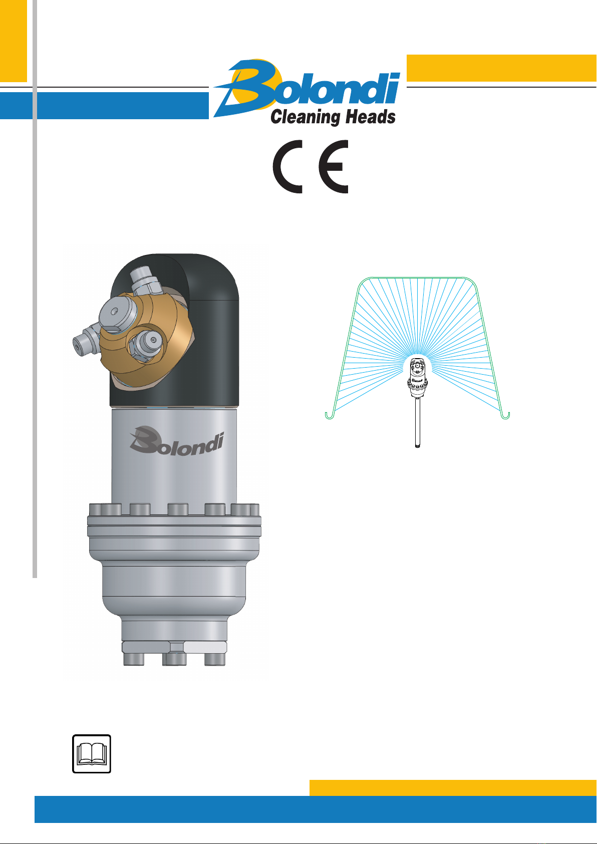
SERVICE MANUALSERVICE MANUAL
SW 053-A.01
SERIAL N°:XXXXXXXX
WARNING: THIS MANUAL IS AN INTEGRAL PART OF THE MACHINE AND MUST BE READ AND
KEPT FOR REFERENCE
Translation of the original instructions

SW 053-A.01-MANUAL Rev.00
Last update 02.12.2020
2
INDEX
DECLARATION OF INCORPORATION OF INCOMPLETE MACHINES.....................................3
REFERENCE LEGISLATION .........................................................................................4
TERMS OF WARRANTY...............................................................................................5
1) INTRODUCTION ...................................................................................................6
2) RECEIVING AND UNPACKING .................................................................................7
3) CONDITIONS AND LIMITS OF USE ..........................................................................8
4) GENERAL SAFETY INSTRUCTIONS...........................................................................9
5) TECHNICAL SPECIFICATIONS .................................................................................10
6) DIAGRAM OF THE ASSEMBLY .................................................................................12
7) INSTALLATION AND COMMISSIONING (WARNINGS)..................................................13
8) CHOICE OF DIFFUSER ACCORDING TO FLOW RATE ...................................................14
9) MAINTENANCE .....................................................................................................15
10) SPARE PARTS .....................................................................................................26
TABLE “B” TORQUE WRENCH SETTINGS.......................................................................27
EXPLODED VIEW ......................................................................................................28
3
SW 053-A.01-MANUAL Rev.00
Last update 02.12.2020
DECLARATION OF INCORPORATION OF INCOMPLETE MACHINES
The undersigned Bolondi Ivano in his role of Legal Representative of Ocina meccanica
Bolondi Ivano and Person authorised to constitute the technical folder, DECLARES under
his own responsibility that the material supplied, indicated in this manual and to which this
declaration refers, consists of a washing head that complies with:
– The applicable essential safety requirements (1.1.2 – 1.1.3 – 1.1.5 – 1.3.1 – 1.3.2 –
1.3.3 – 1.3.4 – 1.3.9 – 1.5.1 - 1.5.2 – 1.5.3 – 1.5.4 – 1.5.6 – 1.5.7 – 1.5.8 – 1.5.13 –
1.5.14 – 1.6 – 1.7) of appendix I of machinery directive 2006/42/EC
– The applicable essential safety requirements of directive 2014/68/UE (pressurised
equipment classied in art. 4 cat. 3)
It also complies with the following harmonised European standards:
ISO TR 14121-2:2013 - Guidance document for risk assessment
UNI EN ISO 12100:2010 - Safety of machinery - General principles for design.
The undersigned also declares that the incomplete machine cannot be started-up until the
machine on which it will be incorporated and of which it will become part has been identied
and declared to be compliant with the provisions of directive 2006/42/EC; in other words
until the incomplete machine to which this declaration refers has become an integral part of
the end machine.
The pertinent technical documents have been drawn-up in compliance with appendix VII B.
We shall forward the information concerning the incomplete machine by fax, e-mail or other
means following a reasonable request from National authorities.
(00A-01CE-00-EN)
BOLONDI IVANO
The legal representative
Ivano Bolondi

SW 053-A.01-MANUAL Rev.00
Last update 02.12.2020
4
REFERENCE LEGISLATION
AIRBORNE NOISE AND VIBRATIONS:
Sound intensity measurements relating to the noise produced by the machine were taken in
compliance with DIR. 2006/42/CE.
The acoustic pressure was measured at the workstation, at 1 m from the machine surface
and 1.6 m o the ground, in normal machine operating conditions.
Sound intensity measurements gave readings below 70 dB(A).
Measurement of vibrations was not made as these were considered clearly below risk levels.
The intensity of the sound produced by machine operation is normally below sound intensity
caused by the impact of washing water against the walls to be washed.
(00D-LdrCE-00-EN)

5
SW 053-A.01-MANUAL Rev.00
Last update 02.12.2020
TERMS OF WARRANTY
1) The manufacturer guarantees the rotating head to be free of manufacturing or material
defects.
2) Warranty: 2 years for EC countries, 1 year for countries outside the EC (valid from date
of delivery).
3) The warranty excludes: all parts subject to normal wear, damage due to carelessness or
improper use.
4) The validity of the warranty shall be decided indisputably by the manufacturer.
5) The warranty excludes labour and transport costs, which are always the responsibility of the
purchaser.
6) All spare parts replaced under warranty must be returned to the manufacturer, carriage
paid, within a maximum of 20 days..
7) The warranty on the nished product or its components shall be void if the product is
tampered with, modied, or has parts manufactured by third parties installed on it wi-
thout prior authorisation from Bolondi.
8) Competent court: Judicial Authority of the court of Reggio Emilia, Italy
(00C-Garanzia-00-EN)
SW 053-A.01-MANUAL Rev.00
Last update 02.12.2020
6
INTRODUCTION
1
Read this operating and maintenance manually carefully before using the head. Only by
following the instructions herein and becoming familiar with the symbols used is it possible
to obtain conditions of maximum eciency and safety. The contents of this manual are in
compliance with machine directive 2006/42/EC and subsequent amendments. The Manu-
facturer reserves the right to make any modications without notice and without incurring
any sanctions on condition that the main technical safety features are not aected. The
Manufacturer is not responsible for personal injury or material damage resulting from the
non-observance of the indications that accompany the symbol.
N.B.:
For accident prevention purposes the equipment must be tted with suitable devices to
prevent automatic re-starting when the equipment is powered after a shut-down. The head
must not be used without these devices. The Manufacturer declines all responsibility in the
case of improper use of the equipment.
N.B.:
Please consult the chapter EXPLODED VIEW for all the numbers and references in the
manual.
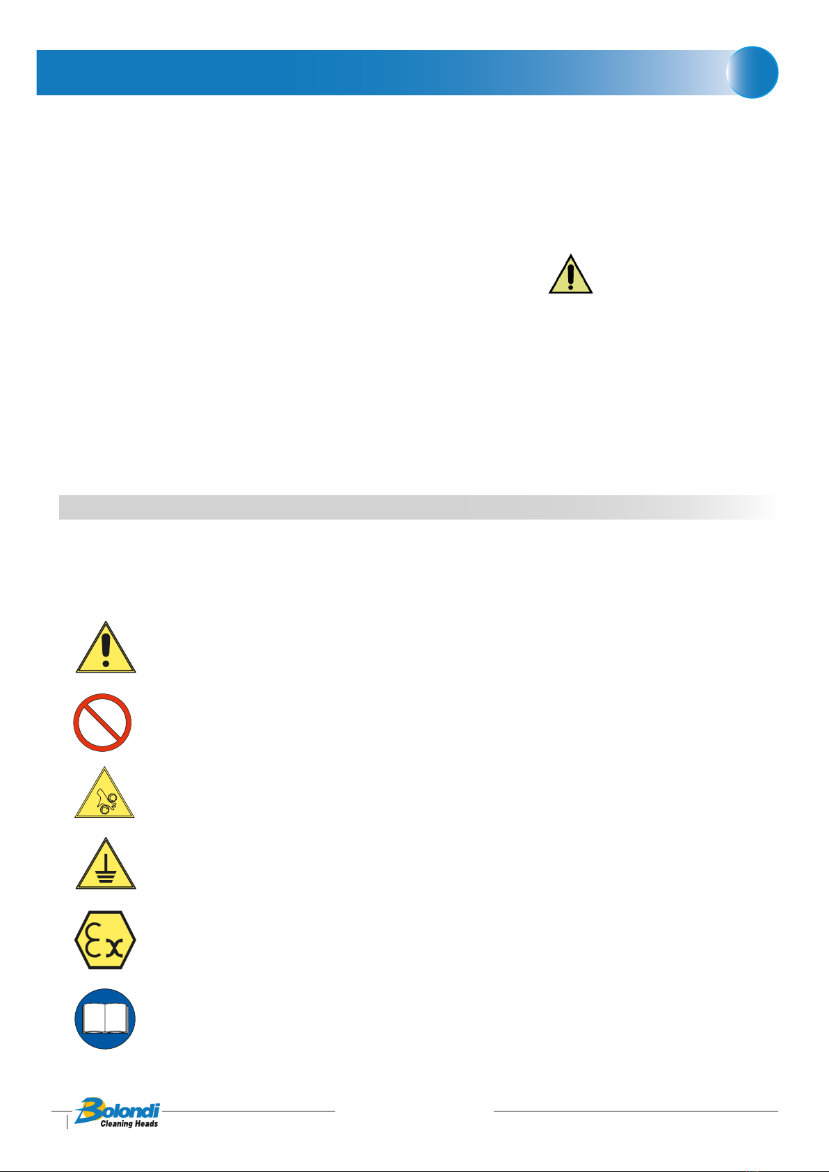
1.1) SAFETY WARNING SYMBOLS
Below are the symbols used in this manual to warn the user of possible risks, which may
arise during handling, positioning and use.
(01-000-01-EN)
WARNING Safety warning sign. Failure to comply can cause serious
personal injuries or damage to the equipment.
PROHIBITION Operations or manoeuvres not permitted
WARNING Moving parts may harm people
HAZARD Ground
PRECAUTION Suggestions and legislation on the subject of protection
against explosions
READ Read the instructions given
7
SW 053-A.01-MANUAL Rev.00
Last update 02.12.2020
RECEIVING AND UNPACKING
2
2.1) CHECKING AND UNPACKING
2.1.1) On receipt, make sure that the model and technical specications correspond with
the order.
2.1.2) Make sure that goods were not damaged during transport.
2.1.3) Any damage found when the goods are received must be documented and the sen-
der informed within 3 days of receipt.
2.1.4) Disposal of packaging: the purchaser is responsible for following the correct proce-
dure and applicable regulations in their country for disposing of the consumables
and refuse created by unpacking the product.
INSTRUCTIONS FOR CORRECT WASTE MANAGEMENT
Material
Paper and cardboard (EWC code 15 01 01)
Plastic (EWC code 15 01 02)
Wood (EWC code 15 01 03)
2.2) DEMOLITION AND DISPOSAL
It is the purchaser’s responsibility to follow the correct procedure and comply with the cur-
rent laws in force in his country as regards to disposing of consumables and materials resul-
ting from demolition.
Please remember that by waste is meant any substance or object under obligation of dispo-
sal.
According to their origin and pursuant to the above mentioned Decree, waste products are
classied as urban or special waste and, depending on their dangerous characteristics, as
hazardous or non-hazardous waste.
Waste resulting from the demolition of the machine is classied as special waste.
WARNING: it is forbidden to mix together dierent categories of hazardous
waste and hazardous waste with non-hazardous waste.
INSTRUCTIONS FOR THE MOST APPROPRIATE HANDLING OF WASTE
Ferrous materials (EWC code 17 04 05):
As this is recyclable material (secondary raw materials), it should be taken to an authorised
collection centre.
Plastic materials (EWC code 16 02 16):
Recycling permitted where landll disposal is performed for urban-type waste.
Incineration permitted in plants equipped with post-combustion and y-ash capture sy-
stems.
Follow applicable national legislation, as amended.
(02-000-00-EN)

SW 053-A.01-MANUAL Rev.00
Last update 02.12.2020
8
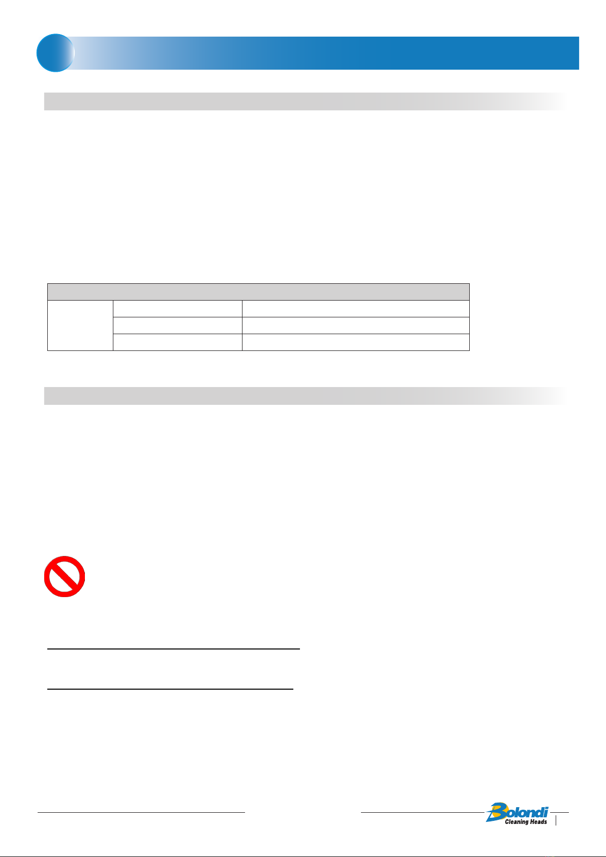
CONDITIONS AND LIMITS OF USE
3.1) Never point the jet of water at people, animals or electrical parts.
3.2) Always check that the equipment and the safety features are in good working before
using the machine. It is forbidden to use the equipment if it is not in perfect condition.
3.3) Intended use: the head was designed exclusively for washing closed contai-
ners.
3.4) Improper use: any other use that does not comply with the safety standards indicated
in this manual is to be considered improper.
3.5) Declaration of the manufacturer: if the head is installed, as a component, on machines
or systems, it is forbidden to use it before the latter have been declared to comply
with the provisions of the Machine Directive.
(03-000-00-EN)
3
9
SW 053-A.01-MANUAL Rev.00
Last update 02.12.2020
GENERAL SAFETY INSTRUCTIONS
4.1) The equipment must be started only by personnel in charge of the plant and only after
it has been validated.
4.2)
Ensure that the device is securely blocked by the anging
.
4.3)
When the equipment is inside the container or plant, check that it does not collide with any
of the moving parts.
4.4) Before start-up, check that all the openings, valves, etc., are closed and allow no pres-
surised jets escape.
4.5) Make sure the supply pipes and connection ttings are suitable for the working pressu-
res/ow rates and for the type of uids used.
4.6) Ensure that the screwed coupling of the connecting hoses is airtight.
4.7) Make sure the supply motor pump is tted with a relief valve and its setting is compati-
ble with the head.
4.8) Make sure the quantity and diameter of the nozzles are suitable for the characteristics
of the plant (pump pressure and ow).
4.9) The high pressure hose must be perfectly intact (to avoid the risk of bursting). If the
high pressure hose is damaged, it must be replaced immediately.
4.10) Do not inspect the container or plant when the head is working or in the presence of
considerable quantities of vapour.
4.11) Each time before using and after each use, make sure the screws are perfectly tight.
See table B “tightening torques”.
4.12) The symbol marked on the head draws the operator’s attention to situations
that could jeopardise workers’ safety.
4.13) The general safety and accident prevention regulations laid down by law must be ob-
served, as well as the warnings given in the operating instructions
(04-00CE-00-EN)
4

10
SW 053-A.01-MANUAL Rev.00
Last update 02.12.2020
TECHNICAL SPECIFICATION
FLOW 10 - 60 LT/MIN
PRESSURE MAX 150 BAR
HYDROSTATIC TEST PRESSURE 255 BAR
MAX OPERATING TEMPERATURE 90 °C
WATER INLET 1/2”
FILTER 700 MICRON
NUMBER OF NOZZLES 2 - 3 - 4
NOZZLES 1/8” NPT
O.RING NBR - EPDM - VITON
SEALS PTFE+CARBON FIBRE
MATERIAL AISI 316 - ALUMINUM - BRASS
MIN.CENTER LINE THROUGH HOLE Ø114 MM
MIN.MANUAL THROUGH HOLE Ø90 MM
DIFFUSER SEE CHART “A”
CONICAL GEARS FIXED Z=22 ROTATING Z=23
MODULE 2
FULL CYCLE 23 ROTATIONS
FULL CYCLE TIME 15” AT 90 RPM
WEIGHT KG ~2,700
5

11
SW 053-A.01-MANUAL Rev.00
Last update 02.12.2020
ᴓ86
112200°°
ᴓ62
204
WATER INLET 1/2”G
VERSIONE
FOGLIO
NOTE:
SCALA
SW053-AA
1:1 A3
CODICE:
01
DATA
01 02 03 04 05
MONTECCHIO E. (RE) - ITALY
CONTR.:
CLEANING HEADS
DATA:
DISEGN.:
09.03.20
CR
VERSIONE
DM
VERSIONE
FOGLIO
DATA
06 07 08 09 10
DESCRIZIONE:
XXXX
09.03.20
SW 053-A.01
APPLICATION DRAWING

12
SW 053-A.01-MANUAL Rev.00
Last update 02.12.2020
DIAGRAM OF THE ASSEMBLY
1) Rotating head
2) Nozzle
3) Nozzle-holder
4) Identication plate
5) Main body
6) Water inlet
(06-SW053-00-EN)
6
5
4
3
2
3-way version 4-way version
1
6

13
SW 053-A.01-MANUAL Rev.00
Last update 02.12.2020 13
INSTALLATION AND COMMISSIONING (WARNINGS)
7
During installation and commissioning, comply with the indications in Chapter 04
of the General Safety Standards in this Manual. If the aforesaid indications are not
complied with, the Manufacturer shall not be held liable.
See the Technical Data Chapter in the Manual for the pump/head connection and
fastening.
Before switching on, it is advisable to ush the system to get rid of any waste or
impurities.
Any breakage or problem due to waste and/or impurities is not covered by the
warranty.
It is advisable to install a 60 micron lter between the head and the pump assembly.
Install a safety valve on the head delivery, set at the maximum pressure indicated
on the rotating head or in the Technical Data Chapter in this Manual.
N.B. Do not turn the nozzle holder by hand.
N.B. The head is calibrated with the specications required in the order.
If there are any changes to these parameters, please contact the Manufacturer.
Any breakages or problems due to parameters that do not conform with specications, shall
not be covered by the warranty.
(07-AQM-00-EN)

14
SW 053-A.01-MANUAL Rev.00
Last update 02.12.2020
CHOICE OF DIFFUSER ACCORDING TO FLOW RATE
(08-CA0285-00-EN)
TABLE “A”
FLOW
LT/MIN 10 15-18 20-25 30-35 40-45 50-55-60
DIFFUSER
CODE
DF1910 DF1920 DF1930 DF1940 DF1950 DF1960
PARAMETERS: 100 BAR - T=20°C
8
Upon consignment, the head is built as requested in the order placed.
If the ow rate is varied, for best use replace the diuser pos.4.
From table “A”, choose the most suitable diuser pos.4 for the new parameters.
It is understood that in the event of variations, the nozzles pos.30 must also be replaced.
Before you make any changes you are recommended to contact the manufacturer.
Follow the procedure given in the maintenance manual to replace the internal diuser.

15
SW 053-A.01-MANUAL Rev.00
Last update 02.12.2020
MAINTENANCE
WARNING:
Disconnect the head from the system before starting any routine or extra-
ordinary maintenance.
IMPORTANT: See the chapter entitled Exploded Drawing for the numbering and refe-
rences used
IMPORTANT: See Table “B” for the torque values of components tightened with a
torque wrench
Lubricant recommended for maintenance: PETRONAS TUTELA ZETA 2 grease.
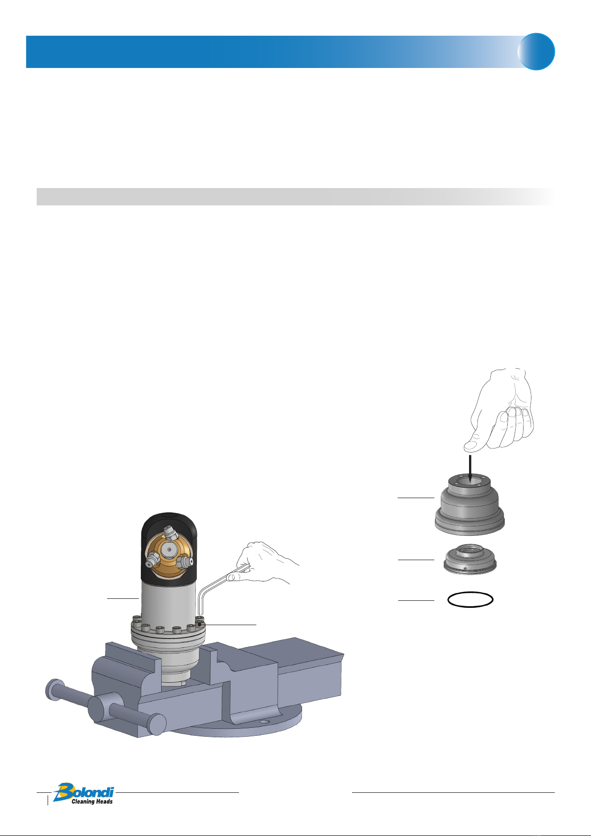
9.1) CLEANING THE INLET FILTER POS.3
Disassembly
9.1.1) Use a 5 mm allen wrench to loosen and remove the screws pos. 2, disassemble the
lter holder ange pos.1, and remove the cartridge pos.3 (Fig.9.00).
9.1.2) Clean the cartridge pos.3 thoroughly, make sure there is no breakage, and t back
in place (pay attention as shown in g.9.01)
Fig. 9.01
3
Ok No 2
1
3
26
Fig. 9.00
9
16
SW 053-A.01-MANUAL Rev.00
Last update 02.12.2020
Assembly
9.1.3) Grease the lter holder ange pos.1 by the O-ring pos.26.
9.1.4) Put the lter holder ange pos.1 back in its seat.
9.1.5) Tighten the screws pos.2 using a torque wrench.
9.2) REPLACING THE DIFFUSOR POS.4
Disassembly
9.2.1) Remove the inlet lter as explained in section 9.1.1.
9.2.2) Use a 5 mm allen wrench to loosen the twelve screws pos.2 from the body pos.23,
see g.9.02.
9.2.3) Remove the top casing pos.24 and push out the diusor pos.4 (Fig. 9.03), then re-
place it after having selected the desired diusor as per table “A” chapter 8.
MAINTENANCE
Fig. 9.02
2
23
Fig. 9.03
24
4
27
9
17
SW 053-A.01-MANUAL Rev.00
Last update 02.12.2020
Assembly
9.2.4) Check and if necessary replace the O-Ring pos.27.
9.2.5) Fit the diusor on the impeller kit “pos.5”, making sure to position the washer pos.6
correctly (see g.9.04).
9.2.6) Position the top casing and secure it with the twelve screws pos.2.
Use a torque wrench to tighten.
9.2.7) Re-t the inlet lter as specied in section 9.1.3 at 9.1.5.
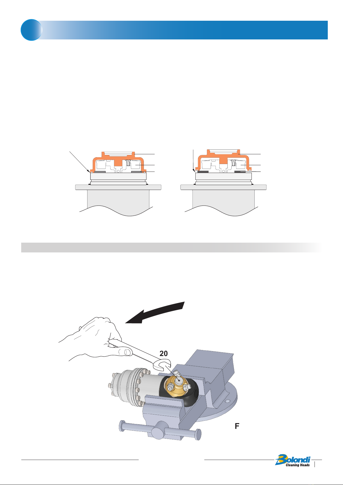
9.3) REPLACING SEALS POS.29 IN THE NOZZLE HOLDER HUB POS.17
Disassembly
9.3.1) Use a 17 mm xed jaw spanner to unscrew the pin pos.20 (Fig.9.05).
MAINTENANCE
20
Fig. 9.05
9
Fig. 9.04
Pos.4
Kit “Pos.5”
Pos.6
Kit “Pos.5”
Pos.6
Pos.4
OK NO

18
SW 053-A.01-MANUAL Rev.00
Last update 02.12.2020
MAINTENANCE
9.3.2) Slide out the pin pos.20 from the nozzle holder crown and remove the washers
pos.15 - 19 (Fig.9.06).
9.3.3) Use the dedicated tool to remove the seals and the O-ring pos.29 from their seats
on the nozzle holder unit (Fig.9.07).
20
19
17
15
Fig. 9.06
Fig. 9.07
29
9
19
SW 053-A.01-MANUAL Rev.00
Last update 02.12.2020
MAINTENANCE
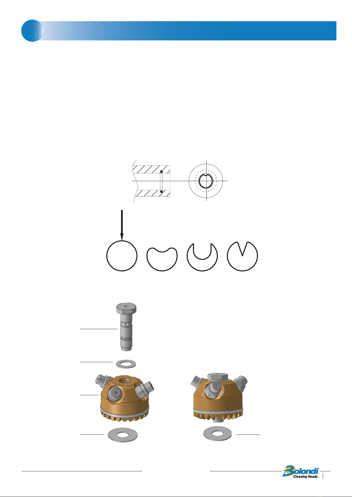
Assembly
9.3.4) Put the O-ring back in its seat rst and then the seal ring pos.29, making it adher
perfectly to the O-ring using a blunt tool. To facilitate the introduction of the ring,
follow the indications shown in g.9.08.
9.3.5) Make sure all components are tted correctly in their seats and lubricate with grea-
se.
9.3.6) Fit the washer pos.19 on the pin pos.20 rst, then insert the pin in the nozzle hol-
der crown (to make it easier to t the threaded part through the seals, turn as if
screwing), then t the second washer pos.15 (Fig.9.09).
OK NO NO
Fig. 9.08
Fig. 9.09
20
19
17
15 15
9

20
SW 053-A.01-MANUAL Rev.00
Last update 02.12.2020
9.3.7) Apply a few drops of loctite 572 on the thread of the pin pos.20, screw the com-
plete unit onto the casing pos.16 (Fig.9.10), and tighten using a 17 mm xed jaw
spanner, checking for correct coupling of the bevel gears pos.13 and pos.17 (see
exploded view diagram).
Use a torque wrench to tighten.
MAINTENANCE
Fig. 9.10
Loctite 572
9
Table of contents
Other Bolondi Cleaning Equipment manuals


