Bolondi XC 061-AAM.04 Manual

OPERATING AND MAINTENANCE
MANUAL HEADS mod. XC 061-AAM.04
XC 061-AAM.02-MANUAL Rev.03
SERIAL N°: 18241334
WARNING: THIS MANUAL IS AN INTEGRAL PART OF THE MACHINE AND
MUST BE READAND KEPT FOR REFERENCE.
Translation of the original instructions

XC 061-AAM.02-MANUAL Rev.03
2
INTRODUCTION
DECLARATION OF INCORPORATION OF INCOMPLETE MACHINES pag. 3
REFERENCE LEGISLATION pag. 4
TERMS OF WARRANTY pag. 4
1) INTRODUCTION pag. 5
2) RECEIVING AND UNPACKING pag. 5 ÷ 6
3) CONDITIONS AND LIMITS OF USE pag. 6
4) GENERAL SAFETY STANDARDS pag. 7
5) TECHNICAL SPECIFICATIONS pag. 8÷9
6) DIAGRAM OF THEASSEMBLY pag. 10
7) INSTALLATION AND COMMISSIONING pag. 10÷11
8) INDICATIVE CHOICE OF THE DIFFUSER
AND NOZZLE BASED ON THE FLOW RATE pag. 12
9) MAINTENANCE pag. 13÷21
10)
SPARE PARTS pag. 22
TABLE “B” TORQUE WRENCH SETTINGS pag. 22
REGISTRATION OF JOBS DONE - NOTE pag. 23÷25
EXPLODED VIEW pag. 26
SPARE PARTS pag. 27

XC 061-AAM.02-MANUAL Rev.03 3
Via Volta 4
42027 Montecchio (R.E.) ITALY
Tel.+39 522 864434 Fax. +39 522 865780
ROTOJET ...
MATRIC. - SERIAL N. ...
ANNO - YEAR ...
PORTATA - FLOW MAX ... lt/min
PRESSIONE - PRESSURE MAX ... bar
TEMP. MAX ... °C
BOLONDI IVANO
The legal representative
Ivano Bolondi
DECLARATION OF INCORPORATION OF INCOMPLETE MACHINES
TheundersignedBolondiIvanoinhisroleofLegalRepresentativeofOfficina
meccanica Bolondi Ivano and Person authorised to constitute the technical
folder, DECLARES under his own responsibility that the material supplied,
indicated in this manual and to which this declaration refers, consists of a
washing head that complies with:
- The applicable essential safety requirements (1.1.2 – 1.1.3 – 1.1.5
– 1.3.1 – 1.3.2 – 1.3.3 –1.3.4 – 1.3.9 – 1.5.2 – 1.5.3 –1.5.4 –1.5.6 –
1.5.7–1.5.8– 1.5.13 – 1.6 – 1.7)ofappendixIofmachinerydirective
2006/42/EC
- The applicable essential safety requirements of directive 97/23/EC
(pressurised equipment classified in art. 3 cat. 3)
It also complies with the following harmonised European standards:
UNI EN 14121:2009 - Risk Assessment Principles
UNIENISO12100:2010-Safetyofmachinery-Generalprinciplesfordesign.
The undersigned also declares that the incomplete machine cannot be
started-up until the machine on which it will be incorporated and of which
it will become part has been identified and declared to be compliant with
the provisions of directive 2006/42/EC; in other words until the incomplete
machine to which this declaration refers has become an integral part of the
end machine.
The pertinent technical documents have been drawn-up in compliance with
appendix VII B.
Weshallforwardtheinformationconcerningtheincompletemachinebyfax,e-
mailorothermeans following a reasonable request fromNationalauthorities.
(00A-01CE-06-EN)

XC 061-AAM.02-MANUAL Rev.03
4
REFERENCE LEGISLATION
AIRBORNE NOISE AND VIBRATIONS:
Sound intensity measurements relating to the noise produced by the machine were taken in
compliance with DIR. 2006/42/EC.
The acoustic pressure was measured at the workstation, at 1 m from the machine surface
and 1.6 m off the ground, in normal machine operating conditions.
Sound intensity measurements gave readings below 70 dB(A).
Measurement of vibrations was not made as these were considered clearly below risk levels.
The intensity of the sound produced by machine operation is normally below sound intensity
caused by the impact of washing water against the walls to be washed.
(00D-010-01-EN)
TERMS OF WARRANTY
1) The Manufacturer guarantees the rotating head as free of material or construction faults
and defects.
2) Warranty: 2 years from the date of delivery for EEC countries, 1 year from the date of
deliveryfornon-EECcountries.Duringthisperiod the Manufacturer undertakes to repair
orreplacepartsthatpresentacknowledgedconstructiondefectsfreeof charge excluding
transport and labour costs which are entirely at the expense of the purchaser.
3) The warranty does not cover: all parts that are subject to wear, parts that have been
damaged due to improper use or negligence; these parts are always and entirely at the
Customer’s expense.
4) The validity of the warranty is at the exclusive and unquestionable judgement of the
Manufacturer.
5) All spare parts replaced under warranty must be returned to the Manufacturer carriage
free within 20 days maximum, failure to do so shall cause the warranty to be invalidated.
6) The warranty shall become invalid if the head is intentionally tampered with without the
written authorisation of the Manufacturer.
7) Any disputes shall be assigned to the jurisdiction of the JudicialAuthority of the Reggio
Emilia Law Court.
(00C-01-Garanzia-EN)

XC 061-AAM.02-MANUAL Rev.03 5
Via Volta 4
42027 Montecchio (R.E.) ITALY
Tel.+39 522 864434 Fax. +39 522 865780
ROTOJET ...
MATRIC. - SERIAL N. ...
ANNO - YEAR ...
PORTATA - FLOW MAX ... lt/min
PRESSIONE - PRESSURE MAX ... bar
TEMP. MAX ... °C
Read this operating and maintenance manually carefully before using the head. Only by
following the instructions herein and becoming familiar with the symbols used is it possible
to obtain conditions of maximum efficiency and safety. The contents of this manual are
in compliance with machine directive 2006/42/EC and subsequent amendments. The
Manufacturer reserves the right to make any modifications without notice and without
incurring any sanctions on condition that the main technical safety features are not affected.
The Manufacturer is not responsible for personal injury or material damage resulting from
the non-observance of the indications that accompany the symbol.
The symbol represents a safety warning.
Failure to follow the instructions given can cause serious personal injury.
N.B.: for accident prevention purposes the equipment must be fitted with suitable
devices to prevent automatic re-starting when the equipment is powered after a shut-
down. The head must not be used without these devices. The Manufacturer declines
all responsibility in the case of improper use of the equipment.
(01-000-01-EN)
2) RECEIVING AND UNPACKING
1) INTRODUCTION
2.1) CHECKING AND UNPACKING
2.1.1) Check on receipt that the goods delivered correspond to those ordered.
2.1.2) Make sure that goods were not damaged during transport.
2.1.3)Any damage found when the goods are received must be documented and the sender
informed within 3 days of receipt.
2.2) MARKING AND IDENTIFICATION
Upon receiving the head, make sure the marking shown
below is identical to that stamped on the machine.

XC 061-AAM.02-MANUAL Rev.03
6
2.3) DEMOLITION AND DISPOSAL
It is the purchaser’s responsibility to follow the correct procedure and comply with the current
laws in force in his country as regards to disposing of consumables and materials resulting
from demolition.
Pleaserememberthatbywaste is meant any substance or object under obligation of disposal.
According to their origin and pursuant to the above mentioned Decree, waste products are
classified as urban or special waste and, depending on their dangerous characteristics, as
hazardous or non-hazardous waste.
Waste resulting from the demolition of the machine is classified as special waste.
WARNING! It is forbidden to mix together different categories of hazardous
waste and hazardous waste with non-hazardous waste.
INSTRUCTIONS FOR THE MOST APPROPRIATE HANDLING OF WASTE.
Ferrous materials:
Ferrous materials are recyclable (secondary raw materials) and must be given to the relevant
authorised collection centres.
Plastics:
Recycling Allowed where carried out.
Dispose of in dumps for waste assimilable to urban waste.
IncinerationAllowed in plants equipped with post-combustion and a system to eliminate dust
before being let into the atmosphere.
(02-000-00-EN)
3) CONDITIONS AND LIMITS OF USE
3.1) Never point the jet of water at people, animals or electrical parts.
3.2) Always check that the equipment and the safety features are in good working
beforeusingthemachine.Itis forbidden to use the equipment if it is not inperfect
condition.
3.3) Intended use: the head was designed exclusively for washing closed
containers.
3.4) Improper use: any other use that does not comply with the safety standards
indicated in this manual is to be considered improper.
3.5) Declaration of the manufacturer: if the head is installed, as a component, on
machinesorsystems,itisforbidden to use it before the latter have been declared
to comply with the provisions of the Machine Directive.
(03-000-00-EN)

XC 061-AAM.02-MANUAL Rev.03 7
4) GENERAL SAFETY STANDARDS
Fig.4.0
2
1
RETE
4.1) The equipment
should be used by
the persons assigned,
having specific training
or having shown the
necessarycompetence,
only. It forbidden for
children or adolescents
to use the equipment.
4.2) Never leave the
equipment unattended.
4.3) Before using, and after
each operation, make
sure the screws are
perfectly tight. See
table B “tightening
torques”.
4.4) Make sure that the
supply motor pump is
fitted with a relief valve
and that the valve
setting is compatible
with the head.
4.5) Makesurethat the supply pipesandconnectionsaresuitablefor the working pressures
and for the type of fluids used.
4.6) Makesure thatthequantity anddiameterof thenozzlesis suitableforthecharacteristics
of the plant (pressure and flow rate of pump).
4.7) Install a relief cock (1) that is as near the water inlet (2) as possible when the head is
in use but always remains on the outside and is easily accessed by the operator (Fig.
4.0).
4.8) The cock should be normally closed and the head should only be started inside the
container to be washed and with the container properly closed.
4.9) The screw connections of all the flexible connecting pipes must be airtight.
4.10) The high pressure flexible pipe must be in perfect condition (danger of bursting). If the
high pressure flexible pipe is damaged it must be replaced immediately.
4.11) Never inspectthecontainerwhentheheadis workingorin thepresenceof considerable
quantities of vapour.
4.12) The symbol marked on the head drawstheoperator’sattentiontosituations
that could compromise human safety.
4.13) The general safety and accident prevention regulations laid down by law must be
observed as well as the warnings given in the operating instructions.
(04-000-02-EN)

XC 061-AAM.02-MANUAL Rev.03
8
5) TECHNICAL SPECIFICATION
FLOW 10 - 60 L/min
PRESSURE 5 - 150 bar
HYDROSTATIC TEST PRESSURE 255 bar
MAX OPERATING TEMPERATURE 90 °C
WATER INLET 1/2”
FILTER 700 MICRON
NUMBER OF NOZZLES 2 - 4
NOZZLES 1/8” NPT
O.RING NBR - EPDM - VITON
SEALS PTFE + CARBON FIBRE
BUSHING AISI 316
MATERIAL AISI 316
MIN.CENTER LINE THROUGH HOLE 95 mm
MAX.MANUAL THROUGH HOLE 76 mm
EXTERNAL HOSE LENGTH ON REQUEST XXXX mm
DIFFUSER SEE CHART “A”
ROTATION SPEED 22 ÷ 28 RPM
FULL CYCLE 31 ROTATIONS
FULL CYCLE TIME 1.3 MIN. A 24 RPM
WEIGHT Kg. 3.5

XC 061-AAM.02-MANUAL Rev.03 9
Ø76
Ø95
XXXX
XXXX
XXXX
ø86
157
1/2"G
ø62
18
ø27
36
31
0.8
RETTIFICA
=XC 061AAM.01
CODICE:
0.8
400-1000
TOLLERANZE GENERALI classe m UNI-EN 22768/1
6-30
0.2
XX.XX.XX
file: XC 061 AAM cm
DESCRIZIONE:
RUGOSITA'
3.2
(UNI 4600)
1.6
SGROSS.
FINITURA
=
=
GREZZO
=
0.1
NOTE:
- -
0-6
DATA
FOGLIO
+:+:
MODIFICA
-
+
120-400
XC 061 AAM.01
APPLICATION DRAWING
0.3
-
30-120
XXXX
+:0.5 -
:+:
123
CLEANING HEADS
MONTECCHIO E. (RE) - ITALY
07.05.08
1000-2000
1.2
-
+:
DISEGN.:
SCALA
DATA:
1:4
CR
45
CONTR.:
A4
DM
0
MOD.
XC 061-AAM.02-MANUAL Rev.03
10
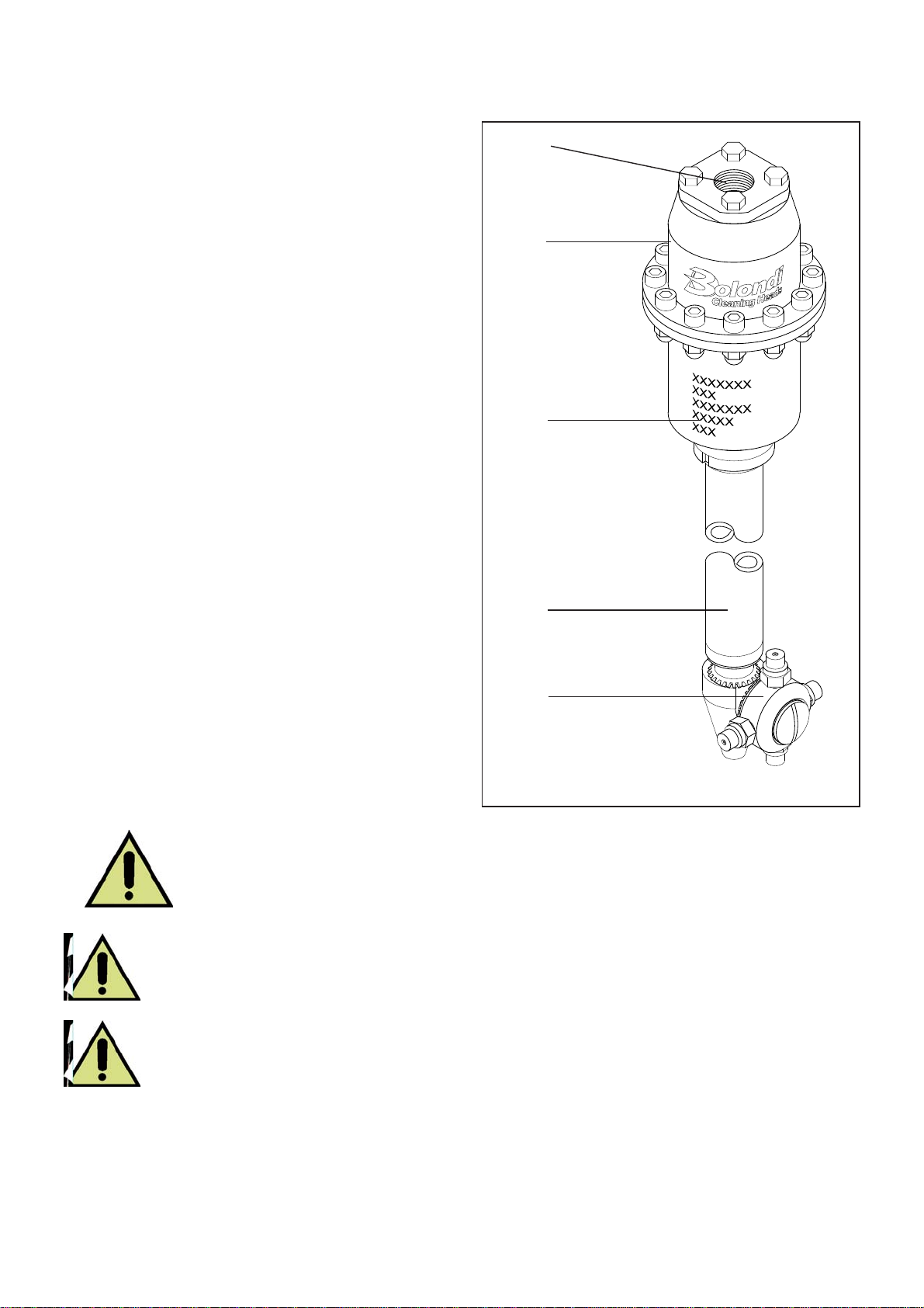
1) Water inlet
2) Main body
3) Identification plate
4) Stem
5) Nozzle-holder
6) DIAGRAM OF THE ASSEMBLY
7) INSTALLATION AND COMMISSIONING
Before you actually start the system, you are recommended to purge it to
eliminate any sludge or impurities. Breakages or problems caused by soiling
will not be accepted under warranty.
On the head inlet install a safety valve set at the maximum pressure shown
on its mark or at page 8 of this manual.
7.1) Put the head (1) in the container to be washed.
7.2) Secure the head to the container via the flange (2). Contact the manufacturer for special
flanges.
Fig. 6.0
2
1
3
4
5

XC 061-AAM.02-MANUAL Rev.03 11
7.3) Make sure the cover of the container is closed correctly (3) to prevent liquid from spur-
ting out in the work phase.
7.4) Connect the head to the pump using a ½” union and high pressure hose [see max.
pressure punched on hose].
Install a safety cock between the head and the supply pump, as explained in chapter 04
section 4.6 4.7.
7.5) Make sure the materials of the head components are compatible with the chemical
specifications of the fluids used.
7.6) Make sure the technical specifications, flow rate and pressure of the head (page 8) are
compatible with the specifications of the pump installed on the system.
7.7) Only in these conditions is the head in the ideal working position, simultaneously having
all the necessary safety requirements.
7.8) The head is set for the specifications indicated on page 8 of this manual. If these para-
meters vary, please contact the manufacturer.
Breakages or problems due to parameters that fail to comply with the specifications
will not be accepted under warranty.
(07-XC061A-01-EN)
Fig. 7.0
1
3
2
RETE

XC 061-AAM.02-MANUAL Rev.03
12
8) INDICATIVECHOICEOFTHEDIFFUSERANDNOZZLEBASED
ON THE FLOW RATE
TABLE “A”
Flow
l / min Diffuser
code Flow
l / min Diffuser
code
15 DF0403 40 DF0419
20 DF0403 45 DF0419
25 DF0405 50 DF0420
30 DF0406 55 DF0420
35 DF0408 60 DF0420
Upon consignment, the head is built as requested in the order placed.
If the flow rate and pressure vary, replace the diffuser (pos.33) and the nozzle (pos.55) to
ensure optimum operation.
From table “A”, choose the most suitable diffuser pos.33 for the new parameters.
Before you make any changes you are recommended to contact the manufacturer.
Follow the procedure given in the maintenance manual to replace the internal diffuser.
(08-RW186AA-00-EN)
XC 061-AAM.02-MANUAL Rev.03 13
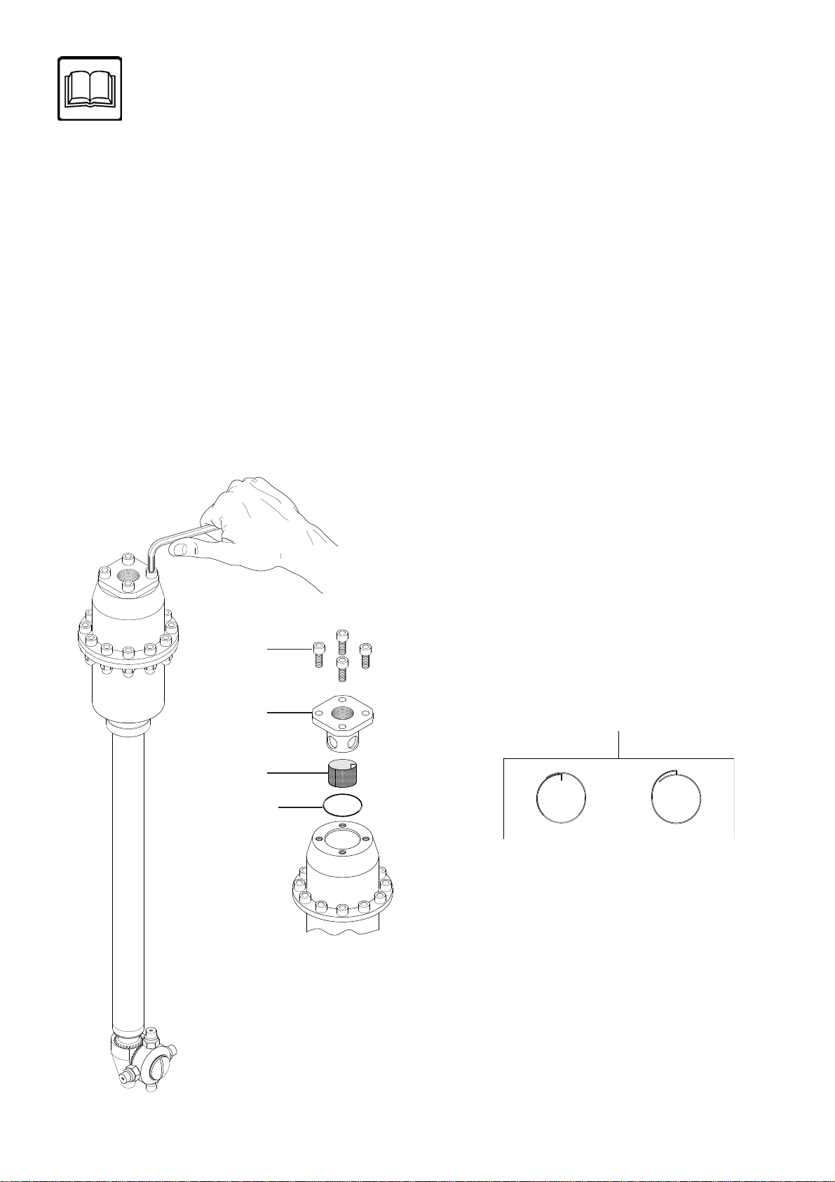
Fig. 9.0
57
62
63
64
9) MAINTENANCE
Fig. 9.1
63
Ok No
WARNING:
Disconnect the head from the hydraulic system before starting any routine or extraor-
dinary maintenance.
(NB. For all the numbers and references written in the chapter refer to the spare parts ex-
ploded diagram on page 26)
(NB. For all the tightening jobs with dynamometric spanner refer to the table “B” on page 22)
9.1) Cleaning the inlet filter pos.63.
Disassembly
9.1.1) Unscrew and remove the screws pos. 57, disassemble the filter holder flange pos.62
and remove the cartridge pos. 63 (Fig.9.0).
9.1.2) Clean the cartridge pos.63 thoroughly, make sure there are no breakages and fit back
in place (pay attention, as in fig.9.1)

XC 061-AAM.02-MANUAL Rev.03
14
Fig. 9.2
Fig. 9.3
1
33
6
Assembly
9.1.3) Lubricate the filter holder flange pos. 62 by the O-ring pos.64 with silicone grease type
KLUBER PARALIQ® GTE 703.
9.1.4) Put the filter holder flange pos. 62 back in its seat.
9.1.5) Screw the screws pos. 57, using a dynamometric spanner.
9.2) Replacing the diffuser pos.33.
Disassembly
9.2.1) Disassemble the inlet filter, as explained in section 9.1.1.
9.2.2) Using a 5-mm hex spanner and a 10-mm ring spanner, unscrew the twelve screws and
the twelve nuts, pos. 57 and pos. 58, see fig. 9.2.
9.2.3) Take the top casing pos. 1 off and push the diffuser kit pos.33 out (fig. 9.3) then replace
after selecting the required diffuser, as in table “A” page 12.

XC 061-AAM.02-MANUAL Rev.03 15
Fig. 9.4
OK NO
Kit“Y”pos.33 Kit“Y”pos.33
Kit “G” Kit “G”
55
Fig. 9.5
86
Fig. 9.6
80 84 86
85
84
82
Fig. 9.7
Assembly
9.2.4) Insert the O-ring, pos. 6 in the seat of the diffuser pos.33 and lubricate with silicone
grease type KLUBER PARALIQ ® GTE 703.
9.2.5) Fit the diffuser kit on the impeller kit “G” making sure to position the washer pos.5
correctly (see fig.9.4).
9.2.6)Positionthetopcasingandsecureitwiththetwelvescrewspos.57andthenutspos.58,
using a dynamometric spanner.
9.2.7) Fit the inlet filter back in place, as explained in section 9.1.3 to 9.1.5.
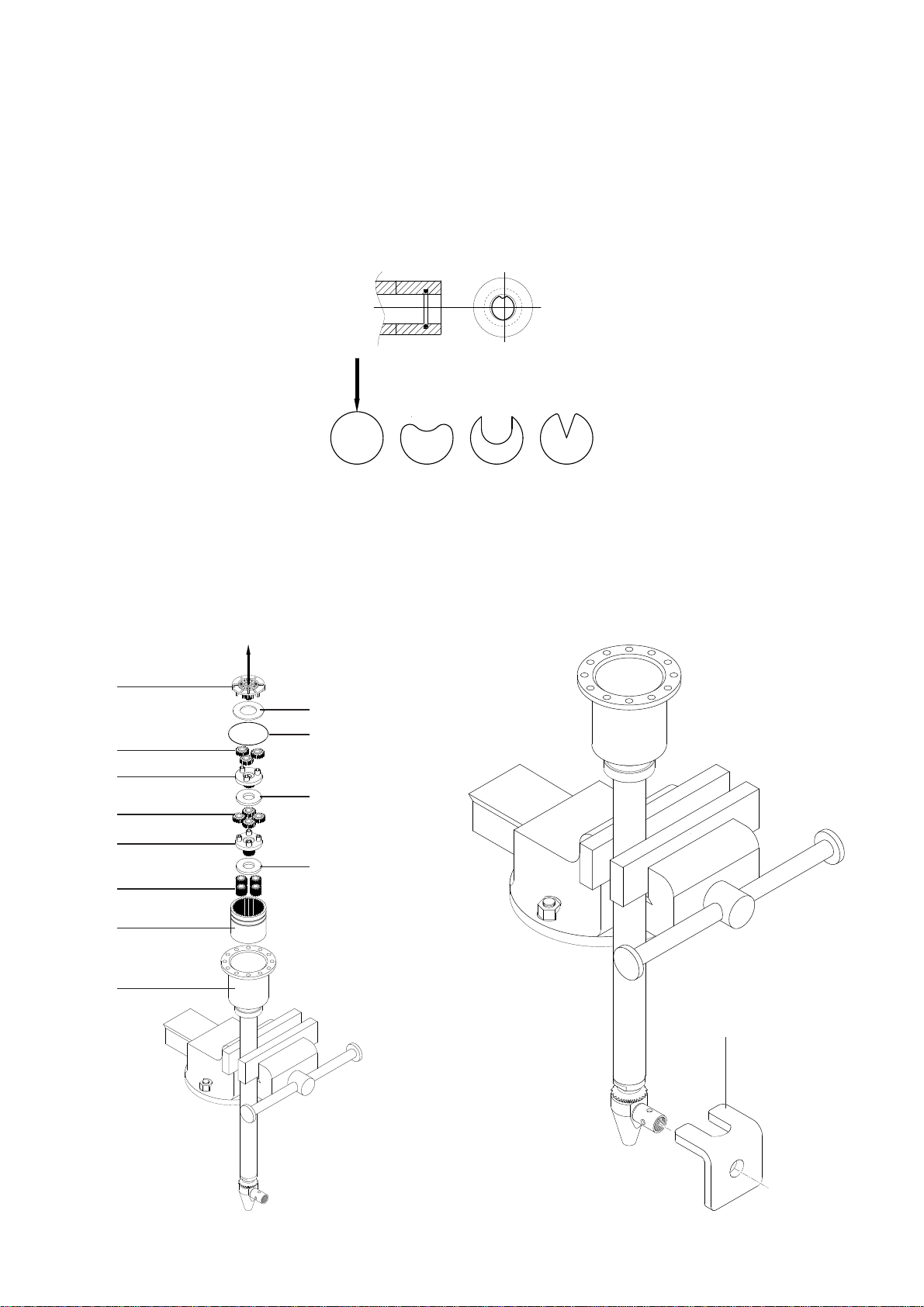
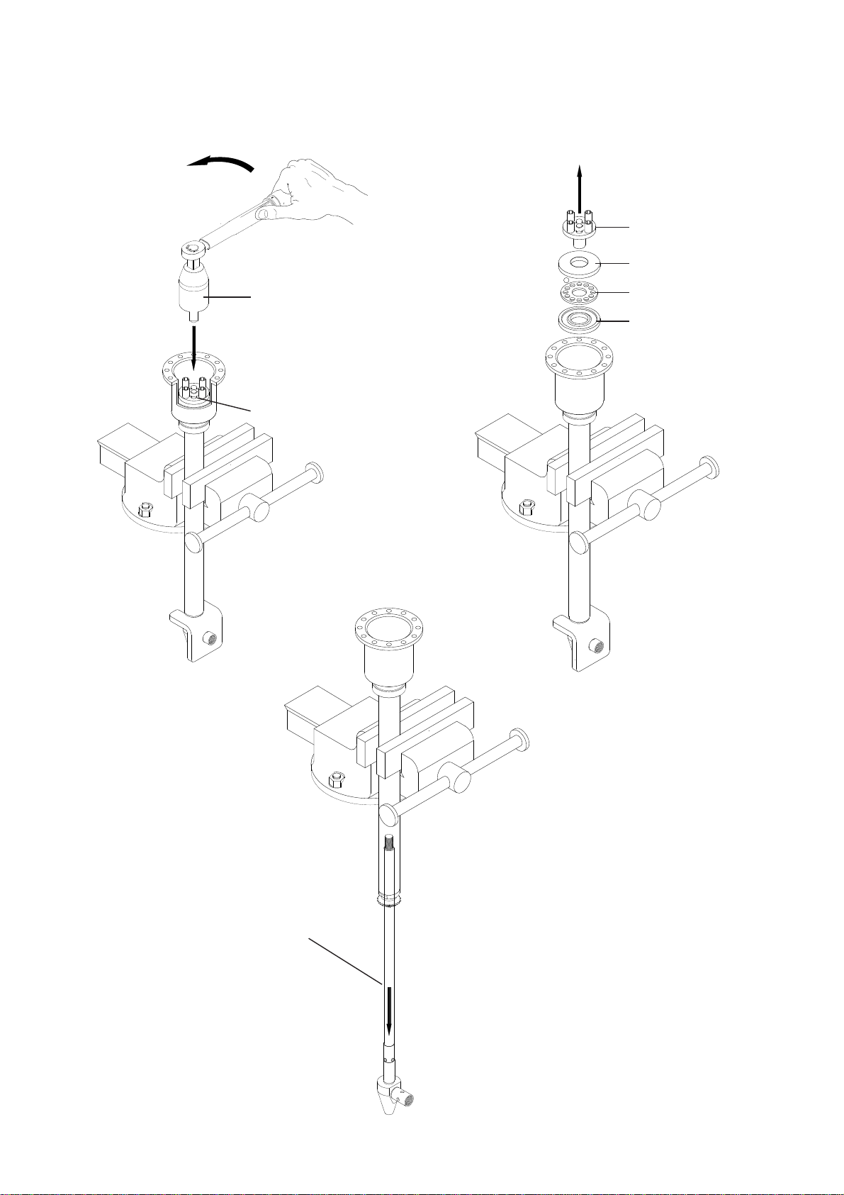
9.3) Replacing the seals (pos.82) on the nozzle holder crown (pos.84)
Disassembly
9.3.1)Clampthehead in a bench vice and, usingasuitablescrewdriver,unscrew and remove
the screw pos.86 and the washer pos.85 (fig.9.5).
9.3.2) Take the crown pos.84 off the pin pos.80 (fig.9.6)
9.3.3) Using the dedicated tool, remove the seals and the o-rings pos.82 from their seats
(fig.9.7).
XC 061-AAM.02-MANUAL Rev.03
16
Fig. 9.8
OK NO NO
Fig. 9.9 Fig. 9.10
ZB0035
10 8
8
6
5
15
32
13
29
34
31
40
Kit “F2”
Kit “E1”
Kit “F1”
Kit “E”
Kit “F”
Kit “G”
Assembly
9.3.4)First fittheO-ringbackin its seat andthenthesealring pos.82 makingtheO-ringadhere
perfectlyusingablunttool.Tomake it easier to insert the ring, follow the instructions in fig. 9.8.
9.3.5) Make sure everything is fitted correctly in its seat and lubricate with silicone grease
type KLUBER PARALIQ ® GTE 703.
9.3.6) Insert the following on the pin pos.80 in the given sequence: the nozzle holder crown
pos.84, the washer pos.85, the tightening screw pos.86. Put some Loctite 222 on the thread
of the screw (pos.86) and tighten with a suitable screwdriver.
9.4) Replacing the seals pos.52 on the pinion pos.72.
Disassembly
9.4.1) Once you have disassembled the head, as explained in sections 9.1.1 and 9.2.2, take
all the parts out as in fig.9.9
9.4.2) Lock the end part using a dedicated tool (ZB0035) as in fig.9.10
XC 061-AAM.02-MANUAL Rev.03 17
Fig. 9.11 Fig. 9.12
ZB0031
Kit “D”
18 (Kit “D”)
45
43-44 (Kit “C”)
45
Fig. 9.13
“A”
9.4.3) Using the spanner supplied ZB0031 unscrew and disassemble the output shaft ( Kit
“D”), the bearing unit pos.43-44-45 (Fig.9.11 – 9.12).
9.4.4) Slide the complete internal rod out “A” (fig.9.13)

XC 061-AAM.02-MANUAL Rev.03
18
Fig. 9.14
72
52
Fig. 9.15
9.4.5) Using a 22-mm fixed jaw spanner, unscrew the pinion pos.72 from the external hose
pos.71
ATTENTION! LEFT-HAND SCREW THREAD (fig.9.13).
9.4.6)Usingthespecial tool,removetheringand o-ringpos.72fromthepinion pos.73(fig.9.14).
Assembly
9.4.7) First fit the O-ring back in its seat and then the seal ring pos.52 making the O-ring
adhere perfectly using a blunt
tool. To make it easier to insert the ring, follow the instructions in fig.9.8. page 16.
9.4.8) Make sure everything is fitted correctly in its seat and lubricate with silicone grease
type KLUBER PARALIQ ® GTE 703.
9.4.9)Puta few drops of Loctite572onthethreadof the pinion pos.72, screwontotheexternal
hose pos.71 and tighten with a 22-mm fixed jaw spanner
ATTENTION! LEFT-HAND SCREW THREAD (fig.9.15).
9.4.10) Fit the bearing unit pos.43-44-45 in the bottom casing pos.40
9.4.11) Insert the internal rod “A” in the pinion pos.72 fitted previously on the external hose
pos.71 and lock it as in fig. 9.10.

XC 061-AAM.02-MANUAL Rev.03 19
9.4.12) Put a few drops of Loctite 222 on the thread of the output shaft pos.18 (Kit ”D”), screw
the same onto the internal rod and tighten with the special spanner supplied (ZB0031) and
check with dynamometer (fig.9.16).
9.4.13) Fit as explained in section 9.3.6.
Fig. 9.16
ZB0031
Kit “D”
18 (Kit “D”)
Loctite 222

XC 061-AAM.02-MANUAL Rev.03
20
9.4.14) Adjust the ring gear as follows:
a)Usingahexspanner,unscrew and remove the screw pos.39 located on the ring nut pos.67.
b) Loosen the screw pos.38 to release the clamp ring nut pos.67 then move this away from
the casing pos.40 (Fig.9.17).
c) Unscrew the bottom casing pos.40 until the end part and output shaft are unable to turn.
d) Slowly screw the bottom casing pos. 40 again until there is approximately 0.1mm between
the pinion pos.72 and the pin pos.80, (check with gauge) fig.9.18.
Fig. 9.18 80
72 ± 0,1
Fig.9.17
39
67
40
38
58
Table of contents
Other Bolondi Cleaning Equipment manuals


Popular Cleaning Equipment manuals by other brands

DCD
DCD VALOR VORTEX MINI owner's manual

Nilfisk-Advance
Nilfisk-Advance SC530 53 BD GO quick start guide

raycop
raycop RS PRO operating manual

Westfalia
Westfalia 339127 instruction manual

Spray Master Technologies
Spray Master Technologies POWER CLEAN GO 2.0 owner's manual

WIRTH
WIRTH OKTOPUS GL-R600 operating instructions


