Bolondi SW 060-CF.09 User manual
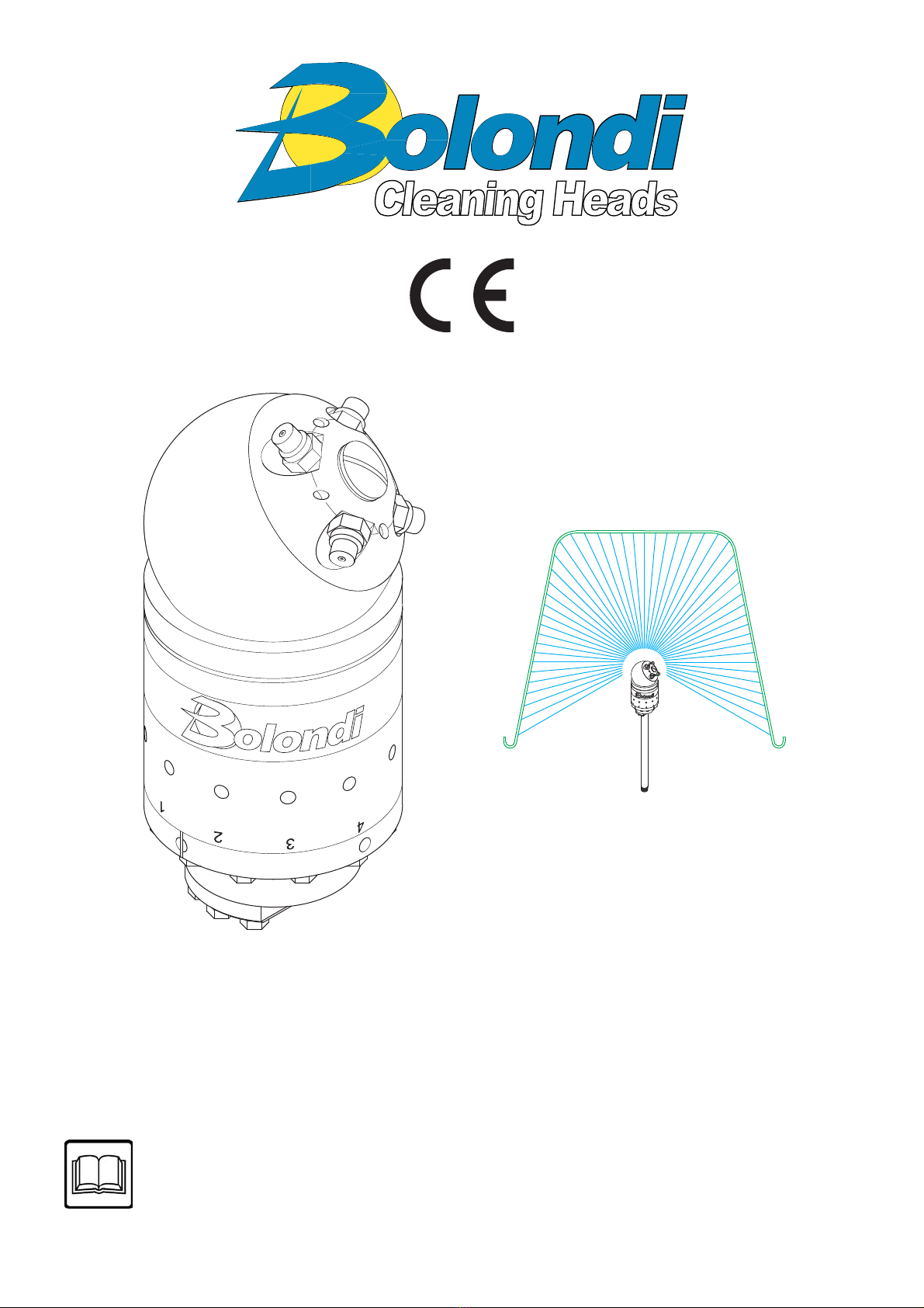
INSTRUCTION MANUAL
HEADS MOD. SW 060-CF.09
SW 060-CF.09-MANUAL Rev.00
SERIAL N°: XXXXXXXX
WARNING: THIS MANUAL IS AN INTEGRAL PART OF THE MACHINE
AND MUST BE READ AND KEPT FOR REFERENCE.
Translation of the original instructions

SW 060-CF.09-MANUAL Rev.00
2
INTRODUCTION
DECLARATION OF INCORPORATION OF INCOMPLETE MACHINES ..................3
REFERENCE LEGISLATION ........................................................................................4
TERMS OF WARRANTY ...............................................................................................5
1) INTRODUCTION ......................................................................................................6
2) RECEIVING AND UNPACKING ..............................................................................7
3) CONDITIONS AND LIMITS OF USE ......................................................................8
4) GENERAL SAFETY INSTRUCTIONS ....................................................................9
5) TECHNICAL SPECIFICATION ..............................................................................10
6) DIAGRAM OF THE ASSEMBLY ............................................................................12
7) INSTALLATION AND COMMISSIONING (WARNINGS) .....................................13
8) SPINNING SPEED CONTROL ..............................................................................14
9) MAINTENANCE ......................................................................................................15
10) SPARE PARTS .......................................................................................................23
TABLE “B” TORQUE WRENCH SETTINGS ..............................................................24
EXPLODED VIEW ........................................................................................................25
NOTES ..........................................................................................................................26

BOLONDI IVANO
The legal representative
Ivano Bolondi
DECLARATION OF INCORPORATION OF INCOMPLETE MACHINES
The undersigned Bolondi Ivano in his role of Legal Representative of Offi cina meccanica
Bolondi Ivano and Person authorised to constitute the technical folder, DECLARES under
his own responsibility that the material supplied, indicated in this manual and to which this
declaration refers, consists of a washing head that complies with:
- The applicable essential safety requirements (1.1.2 – 1.1.3 – 1.1.5 – 1.3.1 – 1.3.2
– 1.3.3 –1.3.4 – 1.3.9 – 1.5.1 – 1.5.2 – 1.5.3 –1.5.4 –1.5.6 – 1.5.7 – 1.5.8 – 1.5.13
– 1.5.14 – 1.6 – 1.7) of appendix I of machinery directive 2006/42/EC
- The applicable essential safety requirements of directive 2014/68/UE (pressurised
equipment classifi ed in art. 4 cat. 3)
It also complies with the following harmonised European standards:
ISO TR 14121-2:2013 - Guidance document for risk assessment
UNI EN ISO 12100:2010 - Safety of machinery - General principles for design.
The undersigned also declares that the incomplete machine cannot be started-up until the
machine on which it will be incorporated and of which it will become part has been identifi ed
and declared to be compliant with the provisions of directive 2006/42/EC; in other words until
the incomplete machine to which this declaration refers has become an integral part of the
end machine.
The pertinent technical documents have been drawn-up in compliance with appendix VII B.
We shall forward the information concerning the incomplete machine by fax, e-mail or other
means following a reasonable request from National authorities.
(00A-01CE-00-EN)
SW 060-CF.09-MANUAL Rev.00 3

REFERENCE LEGISLATION
AIRBORNE NOISE AND VIBRATIONS:
Sound intensity measurements relating to the noise produced by the machine were taken in
compliance with DIR. 2006/42/CE.
The acoustic pressure was measured at the workstation, at 1 m from the machine surface
and 1.6 m off the ground, in normal machine operating conditions.
Sound intensity measurements gave readings below 70 dB(A).
Measurement of vibrations was not made as these were considered clearly below risk levels.
The intensity of the sound produced by machine operation is normally below sound intensity
caused by the impact of washing water against the walls to be washed.
(00D-LdrCE-00-EN)
SW 060-CF.09-MANUAL Rev.00
4

TERMS OF WARRANTY
1) The manufacturer guarantees the rotating head to be free of manufacturing or material
defects.
2) Warranty: 2 years for EC countries, 1 year for countries outside the EC (valid from date
of delivery).
3) The warranty excludes: all parts subject to normal wear, damage due to carelessness
or improper use.
4) The validity of the warranty shall be decided indisputably by the manufacturer.
5) The warranty excludes labour and transport costs, which are always the responsibility
of the purchaser.
6) All spare parts replaced under warranty must be returned to the manufacturer, carriage
paid, within a maximum of 20 days.
7) The warranty on the fi nished product or its components shall be void if the product is
tampered with, modifi ed, or has parts manufactured by third parties installed on it without
prior authorisation from Bolondi.
8) Competent court: Judicial Authority of the court of Reggio Emilia, Italy
(00C-Garanzia-00-IT)
SW 060-CF.09-MANUAL Rev.00 5

Read this operating and maintenance manually carefully before using the head. Only by
following the instructions herein and becoming familiar with the symbols used is it possible
to obtain conditions of maximum effi ciency and safety. The contents of this manual are in
compliance with machine directive 2006/42/CE and subsequent amendments. The Manu-
facturer reserves the right to make any modifi cations without notice and without incurring
any sanctions on condition that the main technical safety features are not aff ected. The
Manufacturer is not responsible for personal injury or material damage resulting from the
non-observance of the indications that accompany the symbol.
The symbol represents a safety warning.
Failure to follow the instructions given can cause serious personal injury.
N.B.:
For accident prevention purposes the equipment must be fi tted with suitable devices to pre-
vent automatic re-starting when the equipment is powered after a shut-down. The head must
not be used without these devices. The Manufacturer declines all responsibility in the case
of improper use of the equipment.
N.B.:
Please consult the chapter EXPLODED VIEW for all the numbers and references in the
manual.
(01-000-00-EN)
1) INTRODUCTION
SW 060-CF.09-MANUAL Rev.00
6

2) RECEIVING AND UNPACKING
2.1) CHECKING AND UNPACKING
2.1.1) On receipt, make sure that the model and technical specifi cations correspond with
the order.
2.1.2) Make sure that goods were not damaged during transport.
2.1.3) Any damage found when the goods are received must be documented and the
sender informed within 3 days of receipt.
2.1.4) Disposal of packaging: the purchaser is responsible for following the correct pro-
cedure and applicable regulations in their country for disposing of the consumables and
refuse created by unpacking the product.
INSTRUCTIONS FOR CORRECT WASTE MANAGEMENT.
Material: Paper and cardboard (EWC code 15 01 01)
Plastic (EWC code 15 01 02)
Wood (EWC code 15 01 03)
2.2) DEMOLITION AND DISPOSAL
It is the purchaser’s responsibility to follow the correct procedure and comply with the current
laws in force in his country as regards to disposing of consumables and materials resulting
from demolition.
Please remember that by waste is meant any substance or object under obligation of dispo-
sal.
According to their origin and pursuant to the above mentioned Decree, waste products are
classifi ed as urban or special waste and, depending on their dangerous characteristics, as
hazardous or non-hazardous waste.
Waste resulting from the demolition of the machine is classifi ed as special waste.
WARNING! It is forbidden to mix together diff erent categories of hazardous waste and
hazardous waste with non-hazardous waste.
INSTRUCTIONS FOR THE MOST APPROPRIATE HANDLING OF WASTE.
Ferrous materials (EWC code 17 04 05)
As this is recyclable material (secondary raw materials), it should be taken to an authorised
collection centre.
Plastic materials (EWC code 16 02 16)
Recycling permitted where landfi ll disposal is performed for urban-type waste.
Incineration permitted in plants equipped with post-combustion and fl y-ash capture systems.
Follow applicable national legislation, as amended.
(02-000-00-EN)
SW 060-CF.09-MANUAL Rev.00 7

3) CONDITIONS AND LIMITS OF USE
3.1) Never point the jet of water at people, animals or electrical parts.
3.2) Always check that the equipment and the safety features are in good working before
using the machine. It is forbidden to use the equipment if it is not in perfect condition.
3.3) Intended use: the head was designed exclusively for washing closed containers.
3.4) Improper use: any other use that does not comply with the safety standards indicated
in this manual is to be considered improper.
3.5) Declaration of the manufacturer: if the head is installed, as a component, on machines
or systems, it is forbidden to use it before the latter have been declared to comply with the
provisions of the Machine Directive.
(03-000-00-EN)
SW 060-CF.09-MANUAL Rev.00
8
4) GENERAL SAFETY INSTRUCTIONS
4.1) The equipment must be started only by personnel in charge of the plant and only after
it has been validated.
4.2) Ensure that the device is securely blocked by the fl anging.
4.3) When the equipment is inside the container or plant, check that it does not collide with
any of the moving parts.
4.4) Before start-up, check that all the openings, valves, etc., are closed and allow no pres-
surised jets escape.
4.5) Make sure the supply pipes and connection fi ttings are suitable for the working pres-
sures/fl ow rates and for the type of fl uids used.
4.6) Ensure that the screwed coupling of the connecting hoses is airtight.
4.7) Make sure the supply motor pump is fi tted with a relief valve and its setting is compat-
ible with the head.
4.8) Make sure the quantity and diameter of the nozzles are suitable for the characteristics
of the plant (pump pressure and fl ow).
4.9) The high pressure hose must be perfectly intact (to avoid the risk of bursting). If the
high pressure hose is damaged, it must be replaced immediately.
4.10) Do not inspect the container or plant when the head is working or in the presence of
considerable quantities of vapour.
4.11) Each time before using and after each use, make sure the screws are perfectly tight.
See table B “tightening torques”.
4.12) The symbol marked on the head draws the operator’s attention to situations
that could jeopardise workers’ safety.
4.13) The general safety and accident prevention regulations laid down by law must be ob-
served, as well as the warnings given in the operating instructions.
(04-000-00-EN)
SW 060-CF.09-MANUAL Rev.00 9

5) TECHNICAL SPECIFICATION
FLOW MAX 60 L/MIN
PRESSURE MAX 200 BAR
HYDROSTATIC TEST PRESSURE 340 BAR
MAX OPERATING TEMPERATURE 90 °C
WATER INLET 1/2” COAXIAL
FILTER 700 MICRON
NUMBER OF NOZZLES 2 - 4
NOZZLES 1/8” NPT
O.RING NBR - EPDM - VITON
SEALS PTFE + CARBON FIBRE
BUSHING B14
MATERIAL ALUMINIUM - BRASS OT58 - AISI 316
MIN.CENTER LINE THROUGH HOLE 100 MM
POSITIONS OF THE DIFFUSER 4
ROTATION SPEED 70 ÷ 120 RPM (SEE CHAPTER 8)
FULL CYCLE 61 ROTATIONS
FULL CYCLE TIME 36 SEC. A 100 RPM
WEIGHT KG. 3,750
*IMPORTANT: CYCLE TIME DEPENDS ON ROTATION SPEED
SW 060-CF.09-MANUAL Rev.00
10
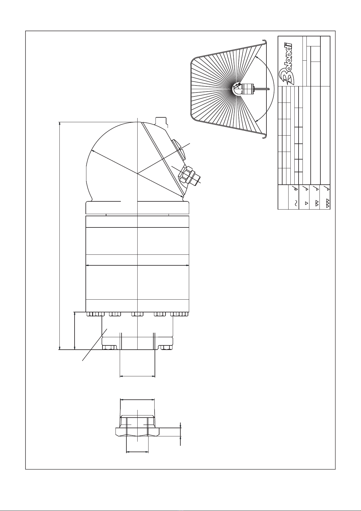
ø100ø100
218
ø100
1"G
1"G
1/2"G
36
8
120°
FILTER
SCALA
DATA:
DISEGN.:
CODICE:
MONTECCHIO E. (RE) - ITALY
3.2 NOTE: VERSIONE 06
0.8
=1.6
=
FINITURA
RETTIFICA
=OPEN CONTAINER VERSION
NON WASHED HOLLW CONE 120°
AQUAMOTOR SECTORDESCRIZIONE:
MATERIALE: INOX+ALLUMINIO
RUGOSITA'
=
SGROSS.
GREZZO
(UNI 4600)
120-400
TOLLERANZE GENERALI classe m UNI-EN 22768/1
XX.XX.XX
XXXX
30-120
1
+
0.1 -
:
DATA
:0.2
6-30
FOGLIO
+
-
0-6
MODIFICA 2
+
-0.5
:
+0.3
-
:1000-2000
43
+
-0.8
:
400-1000
5
+
-
:
1.2 CR CONTR.: DM
A3
SW060A-CF
1:1
18.04.02 MOD.
0
CLEANING HEADS
SW 060-CF.09-MANUAL Rev.00 11
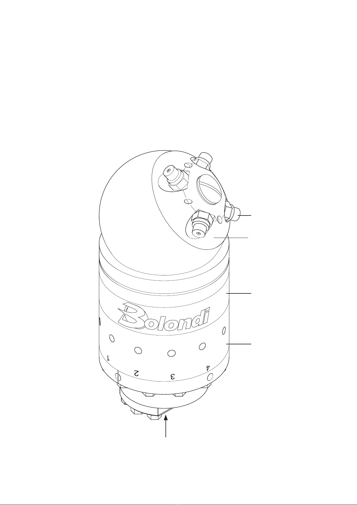
6) DIAGRAM OF THE ASSEMBLY
1) Main body
2) Inlet connection
3) Nozzle-holder
4) Nozzles
5) Identifi cation plate
(06-000-00-EN)
2
3
1
4
5
SW 060-CF.09-MANUAL Rev.00
12
During installation and commissioning, comply with the indications in Chapter 04
of the General Safety Standards in this Manual. If the aforesaid indications are not
complied with, the Manufacturer shall not be held liable.
See the Technical Data Chapter in the Manual for the pump/head connection and
fastening.
Before switching on, it is advisable to fl ush the system to get rid of any waste or
impurities.
Any breakage or problem due to waste and/or impurities is not covered by the
warranty.
It is advisable to install a 60 micron fi lter between the head and the pump assem-
bly.
Install a safety valve on the head delivery, set at the maximum pressure indicated
on the rotating head or in the Technical Data Chapter in this Manual.
N.B. Do not turn the nozzle holder by hand
IMPORTANT: The head is calibrated with the specifi cations required in the order.
If there are any changes to these parameters, please contact the Manufacturer.
Any breakages or problems due to parameters that do not conform with specifi cations, shall
not be covered by the warranty.
(07-AQM-00-EN)
7) INSTALLATION AND COMMISSIONING (WARNINGS)
SW 060-CF.09-MANUAL Rev.00 13
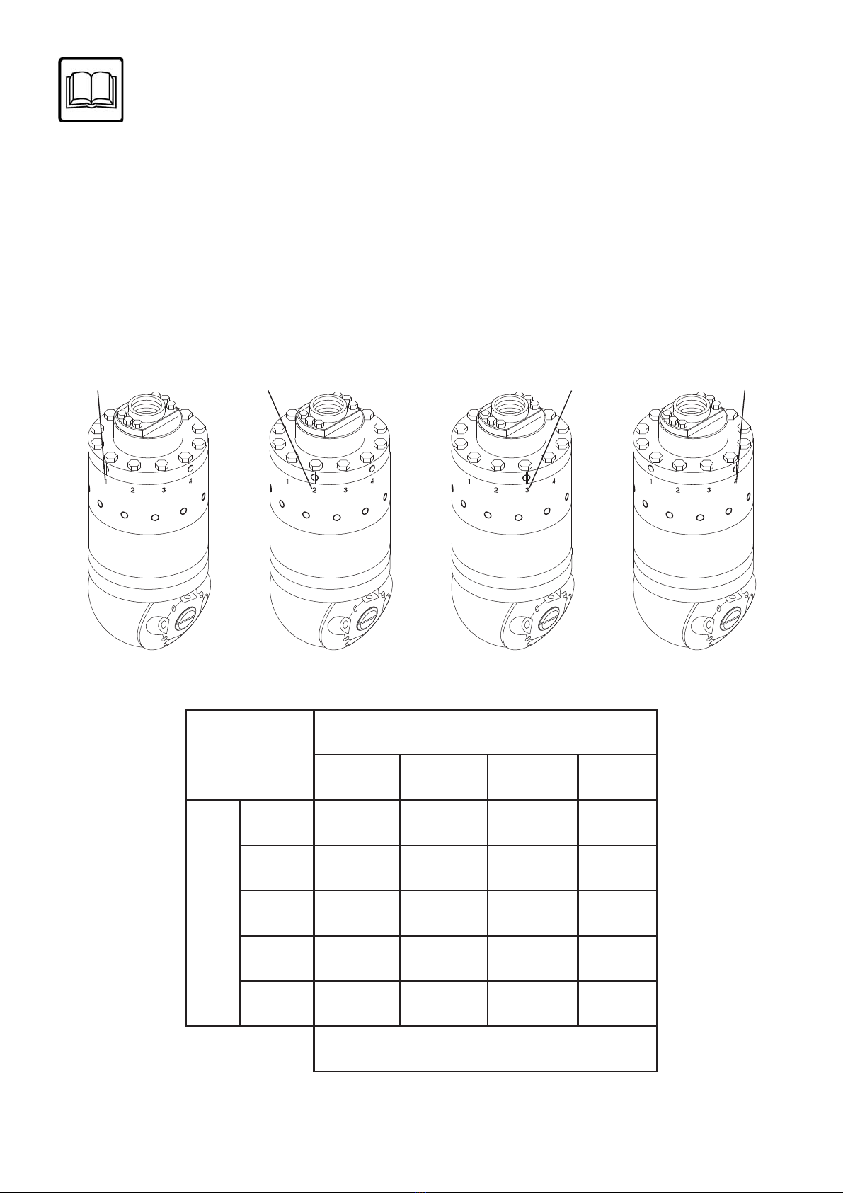
For best performance in relation to the pump fl ow rate (8-60 l/min.) the head should be set
up as described below:
9) Loosen the 12 screws pos.35 using a size 10 wrench.
10) Choose the spinning speed using table A, align the reference mark on the fl ange pos.1
with the corresponding number printed on the diff user pos.33 (Fig.8.0 1, 2, 3, 4).
Tighten the screws pos.35.
(08- CA0500-00-EN)
8) SPINNING SPEED CONTROL
Fig. 8.0
TABLE “A”
DIFFUSER POSITION
12 34
FLOW L / MIN
830
15 78 36
30 90 42
45 72 42
60 96 60
SPINNING SPEED (RPM)
Pos.1 Pos.2 Pos.3 Pos.4
SW 060-CF.09-MANUAL Rev.00
14
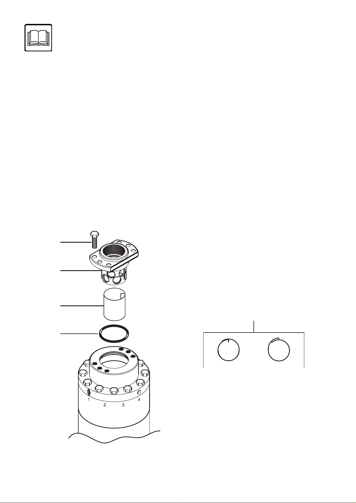
9) MAINTENANCE
Fig. 9.0
Fig. 9.1
Ok
Ok
No
No
61
62
63
64
63
WARNING:
Disconnect the head from the hydraulic system before starting any routine or extraor-
dinary maintenance.
(IMPORTANT: For all the numbers and references written in the chapter, please con-
sult the exploded spare parts drawing).
(IMPORTANT: For all tightening jobs using a torque wrench, please consult table “B”).
Lubricant recommended for maintenance: TUTELA Zeta2 NGLI 2
9.1) Cleaning the inlet fi lter pos. 63.
Disassembly
9.1.1) Unscrew and remove the screws pos. 61, disassemble the fi lter holder fl ange pos.62
and remove the cartridge pos.63 (Fig.9.0).
9.1.2) Clean the cartridge pos.63 thoroughly, make sure there are no breakages and fi t back
in place (pay attention, as per fi g.9.1).
SW 060-CF.09-MANUAL Rev.00 15

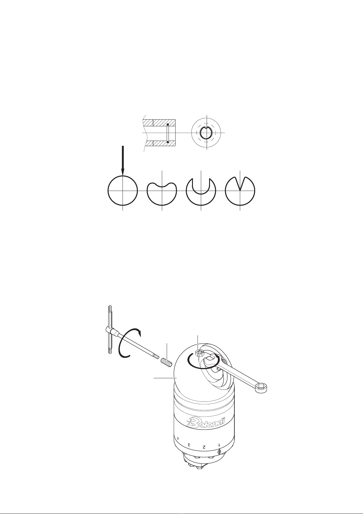
Fig. 9.2
Fig. 9.3 23
23
22
24
19
Assembly
9.1.3) Lubricate the fi lter holder fl ange pos. 62 by the O-ring pos.64.
9.1.4) Put the fi lter holder fl ange pos. 62 back in its seat.
9.1.5) Screw the screws pos. 61, using a torque wrench.
9.2) Replacing the seals pos.23 on the nozzle holder pos.19.
Disassembly
9.2.1) Clamp the head in a bench vice and, using a suitable screwdriver, undo and remove
the screw pos.22.
9.2.2) Remove the washer pos.24, pull the complete nozzle holder out pos.19 (Fig.9.2).
9.2.3) Using the dedicated tool, remove the seal and the O-ring pos.23 from their seats
(Fig.9.3).
SW 060-CF.09-MANUAL Rev.00
16
OK NO NO
Fig. 9.4
13
Fig. 9.5
16
14
18
Assembly
9.2.4) First put the O-ring back in its seat and then the seal ring pos. 23 making it adhere
perfectly to the O-ring using a
blunt tool. To make it easier to insert the ring, follow the instructions in fi g.9.4.
9.2.5) Make sure everything is assembled correctly and greased.
9.2.6) Fit the nozzle holder unit on the pin pos.21.
9.2.7) Position the washer pos.24, put a few drops of Loctite 22 on the screw pos.22 and
then mount it on the pin pos.21 and tighten defi nitively.
9.3) Replacing the seals pos.23 on the bush pos.13.
Disassembly
9.3.1) Once the head has been removed, as in paragraph 9.1.2, remove the washer pos.20.
9.3.2) Keeping the spherical cap blocked pos.16 use a 13 mm ring spanner to undo and
remove the nut pos.18.
9.3.3) Using a 5 mm. hex spanner undo and remove the dowel pos.14 and then remove the
cap pos.16 (Fig.9.5).
SW 060-CF.09-MANUAL Rev.00 17

Fig. 9.6
Fig. 9.7
Fig. 9.8
27
5
8
Kit “G”
Kit “F”
Kit “E”
9.3.4) Using a 6 mm. hex spanner undo and remove the 12 screws pos. 27 (Fig. 9.6).
9.3.5) Position the head as in fi g.9.7 and dismantle the inlet unit.
9.3.6) Dismantle the impeller unit (kit “G”), the fl ange pos.5, the planetary gears pos.29 (kit
“F”) and the gear (kit “E”) with relative washer pos.8 (Fig.9.8).
SW 060-CF.09-MANUAL Rev.00
18

Fig. 9.9 Fig. 9.10
Fig. 9.11
Fig. 9.12
Kit “H”
31
Kit “D”
45
43
44
42
48
11
12
13
48
23
23
9.3.7) Remove the crown pos.31 and the gears (kit “H”) (Fig.9.9).
9.3.8) Remove the pin pos.26 (kit “D”) and the parts pos.45-44-43-42 from the fl ange pos.48
(Fig.9.10).
9.3.9) Using a 4-mm hex spanner, undo and remove the screws pos.11, the pinion pos. 12
and the bush pos.13 from the fl ange pos.48 (Fig.9.11).
9.3.10) Using the dedicated tool, remove the seal and the O-ring pos.23 from their seats
(Fig.9.12).
SW 060-CF.09-MANUAL Rev.00 19

Fig. 9.13
Fig. 9.14
11
12
13
48
Kit “D”
45
43
44
42
48
Assembly
9.3.11) First put the O-ring back in its seat and then the seal ring pos. 23 making it adhere
perfectly to the O-ring using a blunt tool. To make it easier to insert the ring, follow the in-
structions in fi g.9.4.
9.3.12) Make sure everything is assembly correctly and greased.
9.3.13) Check the O-ring pos.40, replacing if necessary and greasing it.
9.3.14) Insert the bush pos.13 and the pinion pos.12 in the fl ange pos.48 and then lock it all
with the screws pos.11 putting a drop of Loctite 222 on them (Fig.9.13).
9.3.15) Insert in sequence parts pos.42-44-43-45 and the output shaft kit “D” in the fl ange
pos.48 (Fig.9.14).
SW 060-CF.09-MANUAL Rev.00
20
Table of contents
Other Bolondi Cleaning Equipment manuals


Popular Cleaning Equipment manuals by other brands

IPC
IPC CT15R quick guide

Larson Electronics
Larson Electronics IND-HVAC-DTW-UVC-R1-SS Series Instruction guide

Mosmatic
Mosmatic DR 520 quick start guide

TEINNOVA
TEINNOVA Tecai rotair user manual

Fantom Professional
Fantom Professional PROMAX 600 CM2 Assembly

ETS NORD
ETS NORD NORDcanopy OZ 3.0 installation guide


