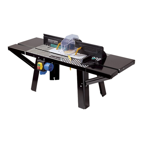
BorMann Technik BRT3000 User manual

Brt3000
|
ΤΡΑΠΕΖΙ ΡΟΥΤΕΡ
Μετάφραση του πρωτοτύπου των
οδηγιών χρήσης
Owner’s manual
Art Nr: 022954
www.BormannTools.com

2
www.BormannTools.com
GB
WARNING: Before operating product, read this manual and follow all its Safety and Operating Instructions.
GENERAL SAFETY INSTRUCTIONS FOR POWER TOOLS
WARNING Failure to heed all safety and operating instructions and warnings regarding use of this product can result in
serious bodily injury.
1. Know your power tool
Read the owner's manual carefully. Learn its application and limitations as well as the specific potential hazards peculiar to
this tool.
2. Ground all tools (unless double insulated)
If tool is equipped with an approved three-conductor cord and a three-prong grounding type plug, it should be plugged into a
three-hole electrical receptacle. If adapter is used to accommodate a two-hole receptacle, the adapter wire must be attached
to a known ground (usually the screw securing receptacle cover plate).
Never remove third prong. Never connect green ground wire to a terminal.
3. Keep guards in place
Maintain in working order, and in proper adjustment and alignment.
4. Remove all adjusting keys and wrenches.
Form a habit of checking to see that keys and adjusting wrenches are removed from tool before turning it ON.
5. Keep work area clean cluttered areas and benches invite accidents. Floor must not be slippery due to wax or sawdust.
6. Avoid dangerous environment
Do not use power tools in damp or wet locations or expose them to rain. Keep work area will lighted. Provide adequate
surrounding work space.
7. Keep children away
All visitors should be kept a safe distance from work area.
8. Make workshop child-proof
Use padlocks, master switches, or remover starter keys.
9. Do not force tools
Do not force tool or attachment to do a job it saw not designed to perform.
10. Use the right tool
They will do the job better and safer at the rate for which they were designed.
11. Wear correct apparel
Do not wear loose clothing, gloves, neckties or jewellery (rings, wrist watches) that may get caught in moving parts.
Non-slip footwear is recommended. Wear protective hair covering to contain long hair. Roll long sleeves above the elbow.
12. Use safety goggles (Head Protection) Wear safety goggles at all times. Also, use face or dust mask, if cutting operation is
dusty, and ear protectors (plugs or muffs) during extended periods of operation.
13. Secure work
Use clamps or a vice to hold work when practical. It's safer are free to operate tool.
14. Do not overreach.
Keep proper footing and balance at all times.
15. Maintain tools with care
Keep tools sharp and clean for best and safest performance. Follow instructions for lubricating and changing accessories
16. Disconnect tools before servicing.
SAFETY GUIDELINES - DEFINITIONS
This manual contains information that
is important for you to know and
understand. This
information relates
to protect
ing YOUR SAFETY and
PREVENTING EQUIPMENT
PROBLEMS.
To help you recognize
this information, we use the symbols
to the right.
Please read the manual and
pay
attention to these sections.
DANGER
Urgent safety information A hazard that
will cause serious injury or loss of life.
CAUTION
Information for preventing damage to
equipment.
NOTE
Information that you should pay special
attention to.
WARNING
Important safety information A hazard
that might cause serious injury or loss
of life.

3
www.BormannTools.com
Before servicing, when changing accessories such as blades, bit, cutters, etc.
17. Avoid accidental starting
Make sure switch is in OFF position before plugging in.
18. Use recommended accessories.
Consult the owner’s manual for recommended accessories and follow the instructions. The use of improper accessories may
cause hazards
19. Never stand on tool
Serious injury could occur if the tool is tipped or if the cutting tools is accidentally contacted. DO NOT store materials above
or near the tool making it necessary to stand on the tool to reach them.
20. Check damaged parts
Before further use of the tool. Any guard or other part that is damaged should be carefully checked to ensure that it will
operate properly and perform its intended function. Check for alignment of moving parts, binding of moving parts, breakage
of parts, mounting, and any other conditions that may affect its operation. A guard or any other part that is damaged should
be properly repaired or replaced.
21. Direction of feed
Feed work into a blade or cutter AGAINST the direction of rotation of the blade or cutter only
22. Never leave tool running unattended Turn power OFF. DO NOT leave tool until it comes to a complete stop.
23. Keep hands away from cutting area 24.Store idle tools
When not in use, tools should be stored in dry, high or locked-up place - out of reach of children.
25. Do not abuse cord
Keep cord away from heat, oil and sharp edges
26. Outdoor extension cords
When tool is used outdoors. Use only extension cords suitable for use outdoors and so marked.
27. Never use in an explosive atmosphere
Normal sparking of the motor could ignite fumes, flammable liquids, or combustible items
28. Drugs, alcohol, medication
DO NOT operate tool while under the influence of drugs, alcohol, or any medication.
Read and understand this instruction book completely BEFORE using this product.
ADDITIONAL SAFETY INSTRUCTIONS FOR ROUTER TABLE
1. Always wear eye protection
2. Noise levels vary widely with location. To avoid possible hearing damage, wear ear plugs or ear muffs when using your
router table for long periods of time.
3. For dusty operations, wear a dust mask along with safety goggles.
4. Follow the instructions in your router owner's manual.
WARNING!
5. Vibrations, caused by the router during use, can cause fasteners to become loose. Before use and periodically during use,
check all fasteners to make sure that all are tight and secure.
6. Do not use this product until all assembly and installation steps have been completed. Make sure you have read and
understand all safety and operational instructions in this manual and the router owner's manual.
7. Make sure that the router bit is properly positioned and clamped in the router before making any cuts.
8. Do not use the router table as a workbench or work surface: Doing so may damage it, causing it to be unsafe to use. A
workbench should be used for this purpose.
9. This product is designed for cutting flat workpieces. Do not cut or attempt to cut workpieces that are not flat.
10. This product is designed for cutting wood workpieces only. Do not use to cut metal or other non-wood materials.
11. The use of auxiliary in-feed and out-feed supports is strongly recommended when routing long workpieces. Otherwise
those workpieces can cause the router table to tip over.
12. Keep hands clear of the router bits and working area.
13. Make and use a push stick to move small workpieces across the cutting area.
14. Clean the router after use. The use of a wet/dry vac or vacuum equipment is recommended.
15. Always make sure that work surface of the router table is clean and free from dust, chips, and foreign particles that can
interfere with the cut you are going to make. The use of a wet/dry vac or vacuum equipment is recommended.
16. The fence that comes with the router table has a dust collector to which a wet/dry vac can be attached.
17. Check the function of the guard before each use. Remove all dust, chips, and any other foreign particles that can affect its
function.

4
www.BormannTools.com
WARNING!
18. Never put your fingers under the overhead guard when the router is plugged into an electrical outlet or when the router
bit is rotating.
19. Always feed the workpiece AGAINST the rotation of the cutter or router bit.
20. Router bits are extremely sharp; be extra careful when handling and using them.
21. Make sure that the router bits being used are sharp or have been properly resharpened. This will permit fast, efficient,
and SAFE routing.
22. Some routers, when positioned in an upside down position (such as on a router table}, will drop or fall out of the router
base when the base clamp is loosened to adjust height or depth of cut. Therefore, it i-s extremely important to support the
router from below when making these adjustments or whenever the base clamp is loosened.
23. Always look under the router table at the router switch box when turning the router ON or OFF. DO NOT touch anything
but the switch box when doing this. NEVER reach under the router table for any reason when the router table is running,
except to turn it OFF.
24. WARNING!
Before making any cut, make sure the router is turned OFF, the router bit is not rotating, and the power cord is unplugged
from the electrical outlet. Then, make absolutely sure that the overhead guard clears the router bit and the workpiece.
A trial pass, with the router turned OFF and the router bit not turning, is strongly recommended.
25. WARNING!
Never leave the router table unattended while the router is running. Turn the router OFF before leaving the router table for
any reason.
INSTRUCTIONS
Your Router Table comes with the following
• A unique fence which allows you to perform these routing operations:
-sliding dovetail joints
-tongue and groove joints
-face cuts
-veining
-fluting
-making crown molding
-making cuts up to 2-1/2" from the edge of the workpiece toward the centre of the workpiece
• An accurate adjusting jointing fence that is quickly adjustable to the proper depth of cut.
• A dust collector port on the fence to which most wet/dry vacs can be attached.
• Adjustable fence facings for maximum workpiece support when routing
• Extensions that provide a large work surface.
• A switch box, with overload protection, to control turning the router ON and OFF. An additional accessor y, such as a
wet/dry vac, can also be plugged into the second receptacle on the back of the switch box.
UNPACKING AND CHECKING CONTENTS
Refer to Parts List
WARNING!If ANY of the parts is missing, DO NOT attempt to assemble, install, or use your router table until the missing
parts have been found or replaced and your router table has been properly and correctly assembled per this manual.
• Contact your local retailer for missing or replacement parts.
• In order to simplify handling and to minimize any damage that may occur during shipping, your router table comes
unassembled.
• Separate all parts from the packaging material and check each part against tr1e illustrations arid the parts list at the end of
this manual, to make sure that all parts have been included. Do this before discarding any of the packaging material.
ASSEMBLY
TOOLS REQUIRED
• Slotted and Phillips screwdriver.
• Small or medium sized adjustable wrench (or a set of nut drivers).
• Electrical or hand drill with 3mm (1/8") drill bit
ROUTER TABLE
NOTE: When the leg with the warning label is assembled to the router table, the warning label MUST BE VISIBLE from the
FRONT of the router table. This means that the leg with the warning label must be on the front right side of the router table
after assembly.
1. Position the router table top as shown in Figure 1, with the back of the table top facing towards you.

5
www.BormannTools.com
2. Position the extension and the table leg relative to the router table top as shown in Figure 1. Note that the legs are
positioned to the inside oi the table top sides. Secure the table leg and extension using two (2) long truss head machine
screws and two (2) hex "KEPS" nuts.
3 Position the switch box against the leg as shown in Figure 1 and 2. Secure the switch box to the leg and the router table top
using two (2) long truss head machine screws and two (2) hex "KEPS" nuts.
Note: There are two hex shaped recesses in the switch box assembly case, into which the hex "KEPS" nuts recess. They
should be inserted nut side into recess with the washer side facing outward.
FIGURE 1
FIGURE 2, ASSEMBLY DETAIL
4. Assemble the remaining legs and the remaining extension to the table top using four (4) long truss head machine screws,
and four (4) hex "KEPS” nuts for each leg Refer to Figure 3 and 4. DO NOT TIGHTEN fasteners at this time.

6
www.BormannTools.com
FIGURE 3
FIGURE 4, ASSEMBLY DETAIL
5. Turn the table right side up and check to see that the extension are even with, or slightly below the router table top.
WARNING! In no case are the extensions to be higher than the surface of the router table top. Such a condition can cause
interference with the workpiece during routing, which can result in possible serious injury.
6. lf the extensions are higher than the top surface of the router table top, loosen the screws holding the extensions, and
reposition them so they are even with or slightly lower than the top of the router table top.
7. SECURELY TIGHTEN all fasteners at this time.
8. To double check, slide a flat piece of wood along the top of the table in all directions. Make sure that the edge of the wood
moves freely without contacting the edges of the extensions.
MOUNTING ROUTER TO THE ROUTER TABLE
ALWAYS UNPLUG ROUTER BEFORE MOUNTING (This table will accept 6 in. diameter base routers) This router table is
equipped with clamps for securing the ma1ority of routers with different base thicknesses and designs on the market The
base or frame of the router being mounted should have a flat surface without any gaps. All clamps MUST contact and secure
the metal portion of the router base or frame.
1. With the router table right side up, insert four (4) long round head square neck bolts, through the four recesses in the
table top, as shown in Figure 5. (HINT: Once. the bolts have been inserted into the bolt recesses on the table top, it will be
helpful to tape over the bolt recess openings. The router will be mounted with the table turned on its top. By taping over the
bolt recesses with the bolts inserted, the likelihood of the bolts failing out as the table is turned on its top will be minimized.)

7
www.BormannTools.com
FIGURE 5
2. With the router table upside down, place the router within the large centering ring in the middle of the table, centering
the router base within the ring. See_ Figure 6 and 7
3. Place four clamps over the four bolts that were previously inserted though the top as shown in Figure 6 and 7.
FIGURE 6
FIGURE 7, ASSEMBLY DETAIL

8
www.BormannTools.com
NOTE: The hex "KEPS" nuts have a yellow finish for easier identification from the hex "KEPS" nuts, which have a zinc (silver)
finish.
5. Loosely secure the clamps at this time.
6. Refer to Figure 8 and 9 for a represent-ation of how the clamps secure the router base. Orient the clamps so that the tab
on the clamp is in complete contact with a portion of the metal base or frame of the router. The support rail on the opposite
end of the clamp should be resting on the support rib. Depending on the shape of the router base, either the short or long
tab end of the clamp may be used to secure the router. For routers which have rib around the base, the long tab end of the
clamp should provide the best clamping arrangement, while routers with a flat style base will be best secured with the short
tab end of the clamp.
FIGURE 8
FIGURE 9
7. With the router centered and the clamps oriented for best clamping force on the router base, TIGHTEN and SECURE the
clamps. There MUST be NO movement of the router in the router table once it has been clamped.
NOTE: Because of the vibration which occurs during routing, occasionally check the clamping of the router to assure there
has been no loosening of the clamps, and that there is NO movement of the router base against the router table.
SELECTING AND INSTALLING THE ROUTER TABLE INSERTS
This router table comes with five table top inserts with the following the hole sizes
• 13mm (1/2") diameter, for use with router bits with diameters up to 10mm (3/8")
• 20mm (3/4") diameter, for use with router bits with diameter up to 16mm (5/8 ")
• 25mm (1") diameter, for use with router bits with diameter up to 22mm (7/8')
• 32mm (1-1/4") diameter, for use with router bits with diameter up to 28mm (1-1/8")
• 38mm (1-1/2 ") diameter, for use with router bits with diameter up to 35mm (1- 3/8")

9
www.BormannTools.com
• For router bits with diameters between 38mm (1-1/2 ") and 41mm (1-5/8"). Do not use a table top insert.
WARNING!A 41mm (1-5/8") Diameter router bit is the LARGEST router bit that can be SAFELY used on this router table.
1. Select the table top insert that accommodates the router bit to be used.
2. The table top inserts are designed to be snapped into the router table top. Insert the large tang under the edge of the
large hole in the route table as shown in Figure 10.
Using your thumb, press down on the insert until the small tang snaps into position.
FIGURE 10
3. To remove, insert a finger in the insert hole and gently pull up until the tabs disengage the hole. When not in use, store the
inserts in a convenient place.
WARNING!
DO NOT attempt to remove table top inserts from the table top unless the router bit has been removed from the router.
UNITIZED FENCE-ASSEMBLY OF JOINTING FENCE TO UNITIZED FENCE
1 Slide the jointing fence through the rectangular opening in the cavity provided on the unitized fence, as shown in Figure 11.
FIGURE 11
2. lnsert a long hex head bolt through the hole with a hex recess in the unitized fence as shown in Figure 12, and through the
slot in the jointing fence as shown in Figure 13
3. While holding the head of the bolt in the hex recess, place a washer over the bolt, and thread the small jointing fence knob
onto the bolt. See Figure 12 and 13

10
www.BormannTools.com
FIGURE 12
FIGURE 13
When the knob is loosened, the jointing fence can slide back and forth in the cavity for proper jointing adjustment.
UNITIZED FENCE-ASSEMBLY OF RETRACTABLE GUARD TO UNITIZED FENCE
1. With the unitized fence upside down on a flat surface, orient the retractable guard as shown ih Figure 14. Position and
hold the spring over the hub on the guard, such that the formed end of the spring wraps over the guard, as shown in Figure
15.
FIGURE 14

11
www.BormannTools.com
FIGURE 15, ASSEMBLY DETAIL
2. While holding the spring over the hub and the formed end over the guard, position and press the straight leg of the spring
against the angled surface of the cavity in the fence which the guard sits in. Slip the guard over the boss spring will now be
trapped
3. Tightly secure the retractable guard in place using the self-threading long pan head platform screw, and the flat washer,
shown in Figure 14.
4. Retract guard into the fence a few times to see that it returns back out to its normal forward position
NOTE: If the guard does not retract back freely, loosen screw just enough for the guard to retract and snap back to its normal
forward position.
ATTACHMENT OF UNITIZED FENCE ASSEMBLY TO ROUTER TABLE
WARNING!
Always unplug router before attaching or removing fence from table.
1. Position unitized fence on router table as shown in Figure 16.
2. Insert a long hex head bolt, from underneath the table, though the hole with a hex recess, as shown in Figure 17, and
through the slot in the fence as shown in
Figure 16.
3. While holding the head of the bolt in the hex recess, place a washer over the bolt, and thread the unitized fence clamping
knob onto the bolt to loosely secure the fence as shown in Figure 16.
4. Repeat for the other slot
FIGURE 16

12
www.BormannTools.com
FIGURE 17
MITRE GAUGE ASSEMBLY
1. Assemble the protractor head to the mitre bar, as shown in Figure 18, using a long truss head machine screw. This screw
will self-thread into the hole in the protractor head.
FIGURE 18
NOTE: There are two round hole in the mitre bar. Make sure the long truss head machine screw enters the hole shown in
Figure 18.
2. Tighten the screw so that it touches the mitre bar but still provides a resistance to rotating the protractor head.
3. Assemble the knob, the washer and the long round head square neck bolt to the mitre gauge, as shown in Figure 19.
FIGURE 19

13
www.BormannTools.com
MOUNTING ROUTER TABLE TO A WORKBENCH OR WORK SURFACE
WARNING! The router table must always be FIRMLY and SECURELY mounted to a work surface before use. Failure to do so
could cause the router table to tip over or slide, resulting in property damage and/or serious personal inJury.
1. Set the router table on a workbench or other stable and sturdy surface, so that the FRONT of the router table faces
toward you, as shown in Figure 20. It may be necessary to loosen the fasteners holding the legs to the table in order to make
the table legs lie flat on the workbench. When the legs are lying flat on the workbench, SECURELY TIGHTEN all fasteners
holding the legs to the router table.
FIGURE 20
2. While holding the router table in place, spot the location of the two mounting holes in each of the legs onto the
workbench. (Total number of holes is eight)
3. Remove the router table from the workbench and set in aside.
4. Drill a 3mm (1/8") diameter hole at each of the spotted hole locations.
5. Position the router table on the workbench so that the holes in the legs line up with the drilled holes in the workbench.
6. Secure the router table to the workbench using eight long round head wood screws (not provided). Applying a little soap
to the screw threads will make it easier to thread the screws into the drilled holes.
7. TIGHTEN the screws SECURELY
ALTERNATE METHOD
1. Cut a board 460mm (18-1/4") wide by 580mm (23 ") long from a piece of 19mm (3/4") thick wood.
2. Place the router table on the board so that the spacing from the edge of the board to the router table legs is equal on four
sides of the board, as shown in Figure 21. It may be necessary to loosen the fasteners holding the legs to the table in order to
make the table legs lie flat on the board. When the legs are lying flat on the board, SECURELY TIGHTEN all fasteners holding
the legs to the router table.
FIGURE 21
3. While holding the router table in place, spot the location of the two mounting holes in each of the legs onto the board.
(Total number of holes is eight)
4. Remove the router table from the board and set it aside.
5. Drill a 3mm (1/8 ") diameter hole at each of the spotted hole locations.

14
www.BormannTools.com
6. Position the router table on the board so tt1at the holes in the legs line up with the drilled holes in the board.
7.Secure the router table to the board using eight long round head wood screws (not provided). Applying a little soap to the
screw threads will make it easier to thread the screws into the drilled holes.
8. TIGHTEN the screws SECURELY
9. Place the router table on a workbench or other stable and sturdy surface, and firmly secure the board with screws or other
suitable means.
OPERATION
GENERAL
The power switch box is designed to be used with router tables. It provides the convenience of an "ON-OFF" switch box at
the front of the table, thus eliminating the need to reach underneath the table to turn the router "ON" and "OFF".
The power switch box also provides an optional simultaneous "ON-OFF" control of an additional accessory, such as a light,
vacuum, etc. The switch box incorporates an internal, re-settable circuit breaker to provide protection in overload situations.
ELECTRICAL REQUIREMENTS
In the event of a malfunction or breakdown, grounding provides the path of least. Resistance for electric current in order to
reduce the risk of electric shock. This switch box is equipped with an electric cord that has an equipment grounding
connector and a grounding plug. The plug must be plugged into a matching outlet that is properly installed and grounded in
accordance with all local codes and ordinances.
DO NOT modify the plug provided if it will not fit the outlet. Have the proper outlet installed by a qualified electrician.
Improper connection of the equipment grounding conductor can result in risk of an electric shock.
The electrical outlet on the back of the switch box will accept either a two-prong from a DOUBLE INSULATED router or
accessory, or a three-prong grounding type plug.
WARNING! Do not permit fingers to touch terminals of the plug when installing or removing from the outlet. If not properly
grounded, this power tool can present the potential hazard of electrical shock, which can possibly result in death, particularly
when used in a damp location, in proximity to plumbing or out of doors. If an electrical shock occurs, there is always the
potential of a secondary hazard, such as your hands contacting the router bit.
WARNING! Use the switch box only when properly assembled to the router table. Use only with a router which has also been
properly installed on a properly assembled router table.
SWITCH BOX OPERATION
This section explains the operation and features of the switch box prior to plugging the power cord into an electrical outlet.
The intent is to familiarize the user with the switch box operation without actually turning on the router.
The switch box incorporates two positive safety features to prevent inadvertent switching on of the router and the
unauthorized, and possibly hazardous, use by others. Inadvertent switching on of the router is prevented by the clear plastic
switch box cover. The cover must be raised and the switch box manually turned to start the router.
In an emergency, the switch box can be turned OFF by slapping or striking the switch box cover with the hand.
WARNING!Before proceeding any further, make sure the switch on the router is in the OFF position and the switch box is in
the OFF position.
The switch box power cord can now be plugged into a wall outlet.
ROUTER AND SWITCH BOX OPERATION
This section explains operation of the switch box with the power cord plugged into an electrical outlet. The router will turn
ON when the switch box is turned to the ON position.
1. Position the ON-OFF switch on the router in the ON position. Make sure the switch box is in the OFF position when doing
this.
2. To turn the router ON, slide finger under the switch box cover and turn on the switch box, as described in the previous
section.
3. To turn the router OFF, press the switch box cover, as described in the previous section.

15
www.BormannTools.com
INSTALLING THE ROUTER BIT (CUTTER)
Because of the large variation of routers and router bits, certain router bits may not always operate in the desired manner
with this router table.
To ensure that the majority of the most popular bits will perform satisfactorily, install the bit so that the router collect
engages 19mm (3/4") of the router bit shank. If the shank of the router bit bottoms out in the collect, back out the router bit
approximately 1.5mm (1/16") to allow for proper tightening NEVER INSTALL ROUTER BITS WITH LESS THAN 19mm (3/4") OF
SHANK ENGAGEMENT IN THE COLLECT.
USING THE ROUTER TABLE
WARNING! The router table fence assembly on you router table is provided as a guide against which the workpiece should be
held for accuracy in routing. Free hand routing (not holding the workpiece against the fence) is hazardous and should be
strictly avoided without piloted router bits.
ALIGNMENT OF UNITIZED FENCE TO MITRE BAR SLOT
1. Measure the distance from each end of the unitized fence to edge "E” of mitre bar slot on the table, as shown in Figure 22.
If both distances are the same, the fence is parallel to the mitre bar slot if not, loosen the fence clamping knobs and adjust
the fence accordingly.
FIGURE 22
2 Tighten both fence clamping knobs
MAKING SURE THAT THE FENCE ASSEMBLY DOES NOT MOVE.
ADJUSTING DEPTH AND HEIGHT OF CUT
NOTE: The router fence should be parallel or nearly parallel to the mitre bar slot Refer to previous section on ALIGNMENT OF
UNITIZED FENCE TO MITRE BAR SLOT.
UNPLUG the router for these adjustments.
In order to retract the guard and have full access to the router bit for making adjustments, select a board that is smooth with
edges true to each other and its surfaces. Other recommendations are the following:
1. Mark lines "A" and "B" on the end of this board. Line "A" indicates the desired depth of cut (amount of material you want
to remove) and line "B'' indicates the desired cutting height See Figure 23.

16
www.BormannTools.com
FIGURE 23
2. Position the board against the face of the router table unitized fence with the edge resting on the table top and the end
marked with lines "A" and "B" close to the bit. See Figure 23. (This will retract the guard inside the fence and provide access
to the bit for making adjustments. MAKE SURE THE ROUTER IS UNPLUGGED WHEN MAKING ADJUSTMENTS.
3. Loosen both large fence clamping knobs to allow for fence assembly adjustment, and move fence forward or backward
until outermost cutting edge of router bit is aligned with line "A" Tighten both fence clamping knobs.
4. Raise or lower the router until top cutting edge of U1e bit is aligned with line "B" (Refer to your router owner’s manual for
adjusting your router properly)
AFTER MAKING THIS ADJUSTMENT, BE SURE ROUTER IS SECURELY TIGH1ENED IN THE ROUTER BASE, THE BIT IS SECURELY
TIGHTENED IN THE ROUTER CHUCK AND THE ROUTER BASE IS SECURED TIGHTLY TO THE ROUTER TABLE TOP
5. Remove the board from the fence.
Note: You should substitute a scrap board for the actual workpiece while making adjustments.
WARNING!WHEN ADJUSTING HEIGHT OF ROUTER BIT FOR ANY DESIRED CUT, MAKE ABSOLUTELY CERTAIN THAT TOP OF
THE BIT IS BELOW THE INSIDE SURFACE OF THE RETRACTABLE GUARD. CHECK TO SEE THAT THE GUARD RETRACTS FREELY IN
AND OUT OF THE FENCE TO ITS NORMAL POSITION OVER THE ROUTER TABLE HOLE. DO NOT OPERATE ROUTER IF ANY PART
OF THE BIT CONTACTS THE GUARD.
USING ROUTER TABLE AS A JOINTER (FULL EDGE CUTTING)
For maximum strength and accuracy, boards to be joined together should be smooth and true. The edges should be true to
the workpiece surface. You can true the edges on your router table using a straight bit.
1. Check to see if the face of the adjustable jointing fence is flush with the face of the router table fence. If not, loosen the
jointing fence clamping knob on Ute Juint1ng fenc8 and push jointing fence in until it is flush with the router table fence.
Tighten the knob on the jointing fence.
Note: The jointing fence provides a continuous support for the workpiece as it is fed beyond the router bit. The adjustable
jointing fence compensates for the gap created from the removal of material by the router bit. See Figures 24 and 25.
2. Adjust the depth of cut (the material you want to remove) and router bit height as described in the section ADJUSTING
DEPTH AND HEIGHT OF THE CUT. Tightly secure the fence assembly and the router as described before. (MAKE SURE ROUTER
IS UNPLUGGED WHEN MAKING ADJUSTMENTS) See Figure 23. FIGURE 24

17
www.BormannTools.com
FIGURE 24
FIGURE 25 DETAIL
3 Check your adjustment by turning the router "ON" using the switch box, and feed a piece of scrap wood a few inches
beyond the router bit. Then stop and turn the router "OFF" using the switch box.
Note: Feed work AGAINST the direction arrow in Figure 24 and 25.
4 Loosen the adjustable fence clamping knob and move the Jointing fence out, flush against the finished edge of the scrap
wood as shown in Figures 24 and 25. Retighten the adjustable jointing fence knob.
5. Repeat the test cut on the scrap wood.
6. The router table is now ready for use.
Note: For best results when jointing, take very shallow cuts of 0.8mm (1 /32") or less.
EDGE CUTTING WITH NON-PILOTED ROUTER BIT
1. Position the adjustable jointing fence so that its face is flush with the face of the router table fence. Tighten adjustable
jointing fence knob. See Figure 26.

18
www.BormannTools.com
FIGURE 26
2. Adjust the depth of cut (the material you want to remove) and router bit height as described iFl the section ADJUSTING
DEPTH AND HEIGHT OF THE CUT. Tightly secure the fence assembly and the router as described before (MAKE SURE ROUTER
IS UNPLUGGED WHEN MAKING ADJUSTMENTS.)
3. Test cut a piece of scrap wood to make sure the adjustments are satisfactory.
Note: Feed work AGAINST the rotation of the cutter as shown by the direction arrow in Figure 26
4. The router table is now ready for use.
EDGE CUTTING WITH PILOTED ROUTER BIT
1. Position the adjustable jointing fence in the same manner as with non-piloted bits.
2. Move the router table fence back only enough to permit the pilot to control the cutting depth. Positioning the fence as
close to the pilot as possible will serve as a back-up and will help to prevent chances of an accident and possible personal
injury See Figures 27 and 28.
3. Test cut a piece of scrap wood to make sure the adjustment are satisfactory.
FIGURE 27
FIGURE 28, DETAIL ASSEMBLY

19
www.BormannTools.com
Note: Feed work AGAINST the rotation of the cutter as shown by the direction arrow in Figure 27.
Note: If you have purchased RAIL AND STILE CUTTERS for making cabinet door frames on your router table. MAKE SURE THAT
THE FRAME THICKNESS IS NO MORE THAN 19mm (3/4"). If the frame thickness is more than 19mm (3/4"), the top of the
router bit will interfere with the retractable guard on the router table's unitized fence.
ROUTING USING THE MITRE GAUGE
Your mitre gauge will serve as a handy aid when extra support is needed for routing small workpieces or the ends of long
workpieces. See Figure 29.
FIGURE 29
Note: For ALL routing operations requiring use of the mitre gauge along with the fence assembly, be sure to align fence
assembly with the mitre bar slot before making any cuts. Refer to section ALIGNMENT TO UNITIZED FENCE TO MITRE BAR
SLOT.
Mitres can be cut by loosening the protractor head knob, turning the protractor head up to 60° in either direction and
tightening the protractor head knob.
WARNING!
• Always HOLD the workpiece FIRMLY and SECURELY AGAINST the mitre gauge, the router table and the fence assembly
when making this cut.
• Make sure that NEITHER YOUR FINGERS, HANDS, OR ANY PART OF YOUR BODY is in line with the router bit when using the
mitre gauge, or serious bodily injury can occur.
* The manufacturer reserves the right to make minor changes to product design and technical specifications without prior
notice unless these changes significantly affect the performance and safety of the products. The parts described / illustrated
in the pages of the manual of the purchased product may also refer to other models of the manufacturer’s product range,
with similar features, other than the product you have purchased.
* Please note that our equipment has not been designed for use in commercial, trade or industrial applications. Our warranty
will be voided if the machine is used in commercial, trade or industrial businesses or for equivalent purposes.
* To ensure the safety and reliability of the product and the warranty validity, all repair, inspection, repair or replacement
work, including maintenance and special adjustments, must only be carried out by technicians of the authorized service
department of the manufacturer.
Technical Data
Main Table (AL) Dimensions:
335*450mm
Extension Table (Steel):
335*200mm

20
www.BormannTools.com
GR
ΠΡΟΕΙΔΟΠΟΙΗΣΗ: Πριν χρησιμοποιήσετε το προϊόν, διαβάστε αυτό το εγχειρίδιο και ακολουθήστε όλες τις Οδηγίες
Ασφαλείας και Λειτουργίας.
Γενικές οδηγίες ασφαλούς χρήσης των ηλεκτρικών εργαλείων
ΠΡΟΕΙΔΟΠΟΙΗΣΗ! Η μη τήρηση όλων των οδηγιών ασφαλείας και χειρισμού και των προειδοποιήσεων σχετικά με τη χρήση
αυτού του προϊόντος μπορεί να προκαλέσει σοβαρούς τραυματισμούς.
1. Γνωρίστε το ηλεκτρικό σας εργαλείο
Διαβάστε προσεκτικά το εγχειρίδιο. Μάθετε την εφαρμογή και τους περιορισμούς καθώς και τους συγκεκριμένους
πιθανούς κινδύνους που είναι ιδιαίτερα χαρακτηριστικοί για αυτό το εργαλείο.
2. Όλα τα εργαλεία θα πρέπει αν έχουν γείωση (εκτός εάν υπάρχει διπλή μόνωση)
Εάν το εργαλείο είναι εφοδιασμένο με εγκεκριμένο καλώδιο τριών αγωγών και βύσμα με γείωση τριών ακροδεκτών, πρέπει
να συνδέεται σε πρίζα τριών οπών. Εάν χρησιμοποιείται αντάπτορας για πρίζα με δύο οπές, το καλώδιο του αντάπτορα θα
πρέπει να είναι συνδεδεμένο με μια επαφή γείωσης (συνήθως με την πλάκα κάλυψης της υποδοχής της βίδας).
Ποτέ μην αφαιρείτε τον τρίτο ακροδέκτη. Ποτέ μην συνδέετε το καλώδιο της γείωσης σε ένα τερματικό.
3. Μην αφαιρείτε τα μέσα προστασίας και ασφαλείας από το εργαλείο σας.
Διατηρήστε τα σε κατάσταση λειτουργίας, σωστά ρυθμισμένα και ευθυγραμμισμένα.
4. Αφαιρέστε όλα τα εργαλεία ρύθμισης από το εργαλείο.
Δημιουργήστε μια συνήθεια να ελέγχετε ότι τα εργαλεία που χρησιμοποιήσατε κατά την διάρκεια των ρυθμίσεων
αφαιρούνται από το εργαλείο προτού το θέσετε σε λειτουργία.
5. Κρατήστε το χώρο εργασίας καθαρό και τακτοποιημένο. Οι ακατάστατοι χώροι και πάγκοι εργασίας προσκαλούν
ατυχήματα. Το πάτωμα δεν πρέπει να είναι ολισθηρό.
6. Αποφύγετε τις επικίνδυνες καιρικές συνθήκες
Μη χρησιμοποιείτε ηλεκτρικά εργαλεία σε χώρους όπου υπάρχουν υψηλά ποσοστά υγρασίας και μηντα εκθέτετε στη
βροχή. Εξασφαλίστε επαρκή φωτισμό και τον απαραίτητο ελεύθερο χώρο για την εκτέλεση της εργασίας.
7. Κρατήστε τα παιδιά σε απόσταση ασφαλείας.
Όλοι οι παρευρισκόμενοι θα πρέπει να βρίσκονται σε απόσταση ασφαλείας από το χώρο εργασίας.
8. Ασφαλίστε τον χώρο εργασίας, αποτρέποντας τα παιδιά από το να εισέλθουν στον χώρο.
Χρησιμοποιήστε λουκέτα, κεντρικούς διακόπτες ή κλειδιά ασφαλείας.
9. Μην υπερφορτώνετε τα εργαλεία
Μην πιέζετε το εργαλείο ή το εξάρτημα για να κάνετε μια εργασία που δεν έχει σχεδιαστεί για να εκτελέσει.
10. Χρησιμοποιήστε το κατάλληλο εργαλείο για την εργασία
Θα κάνουν καλύτερη και ασφαλέστερη τη δουλειά με το ρυθμό για τον οποίο σχεδιάστηκαν.
11. Φορέστε τον σωστό ρουχισμό
Μη φοράτε χαλαρά ρούχα, γάντια, γραβάτες ή κοσμήματα (δαχτυλίδια, ρολόγια χειρός) που μπορεί να πιαστούν σε
κινούμενα μέρη.
ΚΑΤΕΥΘΥΝΤΗΡΙΕΣ ΓΡΑΜΜΕΣ ΑΣΦΑΛΕΙΑΣ - ΟΡΙΣΜΟΙ
Αυτό το εγχειρίδιο περιέχει
σημαντικές
πληροφορίες τις
οποίες πρέπει
να γνωρίζετ
ε και να
κατανοήσετε
. Αυτές οι
πληροφορίες σχετίζονται με την
προστασία της ΑΣΦΑΛΕΙΑΣ ΣΑΣ
και της
πρόληψης των
προβλημάτων στον εξοπλισμό
σας
. Για να σας βοηθήσουμε να
αναγνωρίσετε αυτές τις
πληροφορίες, χρησιμοποιούμε τα
σύμβολα στα δεξιά.
Διαβάστε το
εγχειρίδιο και δώστε
προσοχή στις ενότητες αυτές.
ΚΙΝΔΥΝΟΣ
Σημαντικές πληροφορίες
ασφαλείας. Κίνδυνος που θα
προκαλέσει σοβαρό τραυματισμό ή
ακόμη και θάνατο.
ΠΡΟΣΟΧΗ
Πληροφορίες
για αποφυγή βλάβης στον
εξοπλισμό.
ΣΗΜΕΙΩΣΗ
Πληροφορίες στις οποίες πρέπει να
δώσετε ιδιαίτερη προσοχή.
ΠΡΟΕΙΔΟΠΟΙΗΣΗ
Σημαντικές πληροφορίες
ασφαλείας. Ένας κίνδυνος που
μπορεί να προκαλέσει σοβαρό
τραυματισμό ή απώλεια ζωής.
This manual suits for next models
1
Table of contents
Languages:
Other BorMann Wood Router manuals