Bosch B465 User manual

Conettix Universal Dual Path
Communicator
B465
en Installation and Operation Manual


Conettix Universal Dual Path Communicator Table of contents | en 3
Bosch Security Systems, Inc. Installation and Operation Manual 2017.11 | 05 | F.01U.311.207
Table of contents
1Safety 7
2Introduction 8
2.1 About documentation 8
2.2 Bosch Security Systems, Inc. product manufacturing dates 8
2.3 Installation workflow 8
3System overview 10
3.1 B465 overview 10
3.2 PSTN reporting format compatibility 12
3.2.1 Phone line voltage 12
3.3 IP communication 13
3.4 B46 overview (optional) 13
4Installation 15
4.1 Remove enclosure knockouts 15
4.2 Mount the enclosure 15
4.3 Insert D101 lock (optional) 16
4.4 Insert B46 LED cover (optional) 16
4.5 Install the B465 in the enclosure 17
4.5.1 Mount the B46 (optional) 17
4.5.2 Connect earth ground 17
4.6 Install the cellular plug-in communicator module (optional) 17
4.7 Wiring installation 19
4.7.1 System wiring 19
4.7.2 Control panel to B465 wiring for dialer capture 21
4.7.3 Control panel to dry contact wiring 22
4.7.4 B46 module wiring (optional) 22
4.7.5 Input loop wiring 23
4.7.6 Output wiring 25
4.7.7 Primary power source wiring 26
4.7.8 D1640-120WI transformer wiring (optional) 29
4.7.9 12 VDC battery wiring 29
5IP Communicators 33
5.1 Onboard Ethernet 33
5.2 Connettix Plug-in Cellular Communicator 33
5.3 Report routing 34
5.4 Compatible central station receivers 36
6Configuration and Diagnostics 37
6.1 RPS 37
6.2 USB and TeraTerm 37
6.2.1 Install TeraTerm 38
6.2.2 Log in 41
6.3 Main Menu 43
6.3.1 Menu Map 44
6.3.2 1 = Status 47
6.3.3 2 = Standard Communication Configuration, 3 = Advanced Communication
Configuration
52
6.3.4 4 = System Configuration 52
6.3.5 5 = Input Configuration, 6 = Output Configuration 52
6.3.6 8 = Maintenance 52

4en | Table of contents Conettix Universal Dual Path Communicator
2017.11 | 05 | F.01U.311.207 Installation and Operation Manual Bosch Security Systems, Inc.
6.4 Firmware Update 53
7Communication Configuration 58
7.1 Account Number / NNC Number 58
7.2 Substitute Account Number 58
7.3 Alternate Account Number 58
7.4 Preferred Network Technology 59
7.5 Alternate Network Technology 59
7.6 Cloud (Remote Connect) 60
7.6.1 Cloud (Remote Connect) Ethernet 60
7.6.2 Cloud (Remote Connect) Cellular 60
7.7 Primary Receiver 60
7.7.1 Ethernet IP Address / Host Name 61
7.7.2 Port Number 61
7.7.3 Ethernet Supervision Time 61
7.7.4 Cellular IP Address / Host Name 62
7.7.5 Cellular Supervision Time 62
7.7.6 AES Encryption, Key Size 62
7.7.7 AES Encryption Key 63
7.8 Number of Receivers 63
7.9 Secondary Receiver 63
7.9.1 Ethernet IP Address / Host Name 63
7.9.2 Port Number 64
7.9.3 Ethernet Supervision Time 64
7.9.4 Cellular IP Address / Host Name 64
7.9.5 Cellular Supervision Time 64
7.9.6 AES Encryption, Key Size 65
7.9.7 AES Encryption Key 65
7.10 Ethernet Setup 65
7.10.1 IPv6 Mode 65
7.10.2 IPv6 DNS Server IP Address 65
7.10.3 Alternate IPv6 DNS Server IP Address 66
7.10.4 IPv6 test address 66
7.10.5 IPv4 DHCP/AutoIP 66
7.10.6 IPv4 Address 67
7.10.7 IPv4 Subnet Mask 67
7.10.8 IPv4 Default Gateway 67
7.10.9 IPv4 DNS Server IP Address 67
7.10.10 Alternate IPv4 DNS Server IP Address 68
7.10.11 IPv4 Test Address 68
7.10.12 UPnP (Universal Plug and Play) 68
7.10.13 ARP cache timeout (minutes) 68
7.10.14 B465 Hostname 68
7.10.15 TCP/UDP Port Number 69
7.11 Cellular Setup / Cellular Plug-in Module 69
7.11.1 Network Access Point Name (APN) 69
7.11.2 Network Access Point User Name 69
7.11.3 Network Access Point Password 69
7.11.4 SIM PIN 70
7.11.5 Inbound SMS 70

Conettix Universal Dual Path Communicator Table of contents | en 5
Bosch Security Systems, Inc. Installation and Operation Manual 2017.11 | 05 | F.01U.311.207
7.11.6 Reporting Delay for Low Signal Strength (minutes) 70
7.11.7 Reporting Delay for No Towers (minutes) 70
7.11.8 IPv4 DNS Server IP Address 71
7.11.9 Alternate IPv4 DNS Server IP Address 71
7.11.10 IPv4 Test Address 71
8System Configuration 72
8.1 Panel Phone Line Setup 72
8.1.1 Panel Reporting Format 72
8.1.2 Tone Duration (milliseconds) 72
8.2 Primary Power Supervision 72
8.2.1 Primary Power Source 72
8.2.2 Primary Power Fail Delay 73
8.2.3 Primary Power Fail sends reports 73
8.2.4 Primary Power Fail sets Trouble Output 73
8.3 Battery Supervision 73
8.3.1 Battery Monitoring 73
8.3.2 Battery faults send reports 74
8.3.3 Battery faults set Trouble Output 74
8.4 Tamper 74
8.4.1 Tamper sends reports 74
8.4.2 Tamper sets Trouble Output 74
8.5 Communication Failure Action 75
8.5.1 Comm Fail sends reports 75
8.5.2 Comm Failure sets Trouble Output 75
8.5.3 Comm Failure removes Line 1 phone voltage 75
8.5.4 Comm Failure removes Line 2 phone voltage 75
8.6 Module Supervision 76
8.6.1 Module Faults send reports 76
8.6.2 Module Faults set Trouble Output 76
8.7 RPS Settings 76
8.7.1 RPS Passcode 76
8.7.2 Answer RPS over Network 76
8.8 USB Terminal Passcode 76
8.9 Test Report 77
8.9.1 Test Report Interval 77
9Input Configuration 78
9.1 Input 1 (to 4) 78
10 Output Configuration 79
10.1 Output 1 (to 3) 79
11 Maintenance and troubleshooting 80
11.1 B465 LED status indicators 80
11.2 B46 LED status and sounder 86
11.3 Show the firmware version 88
11.4 Diagnostic log 89
11.5 Understanding network polling 89
11.6 Troubleshooting procedures 89
11.6.1 No power on the B465 89
11.6.2 Initialization - cellular 89
11.6.3 Hardware 90

6en | Table of contents Conettix Universal Dual Path Communicator
2017.11 | 05 | F.01U.311.207 Installation and Operation Manual Bosch Security Systems, Inc.
11.6.4 Firmware 90
11.6.5 SIM card 90
11.6.6 PIN code 90
11.6.7 Cellular network registration 91
11.6.8 USB COM port error 91
11.7 Testing the system 92
12 Specifications and certifications 94
12.1 Technical specifications 94
12.1.1 B465 power supply specifications 96
12.1.2 Application environment 97
12.1.3 Standby battery requirements and calculations 98
12.1.4 24 VDC Input power requirements 99
12.1.5 Required programming to meet UL 864 100
12.1.6 Required programming to meet ULC-S304 102
12.1.7 Required programming to meet ULC-S559 102
12.1.8 Compatible UL listed components 104
12.2 Certifications 107
12.3 B465 Event/Report Table 108

Conettix Universal Dual Path Communicator Safety | en 7
Bosch Security Systems, Inc. Installation and Operation Manual 2017.11 | 05 | F.01U.311.207
1 Safety
ESD precaution
Please note that the B465 Universal Dual Path Communicator and optional plug-in cellular
modules come in a plastic bags, and are protected from ESD. All plug-in cellular communicator
components may potentially be exposed to finger touches - therefore extra attention must be
paid to ESD (electrostatic discharge) precaution. Make sure there is no static interference
when using the board. Appropriate ESD protections must be taken and wearing electrostatic
equipment is recommended, such as anti-static wrist strap.
ESD damage can range from subtle performance degradation to complete device failure.
Precision integrated circuits may be more susceptible to damage because very small
parametric changes could cause the device not to meet its published specifications.
!
Warning!
Failure to follow these instructions can result in a failure to initiate alarm conditions
Bosch Security Systems, Inc. is not responsible for improperly installed, tested, or maintained
devices. Follow these instructions to avoid personal injury and damage to the equipment.
Notice!
Inform the operator and the local authority having jurisdiction (AHJ) before installing the
module in an existing system.
Disconnect all power to the control panel before installing the module.

8en | Introduction Conettix Universal Dual Path Communicator
2017.11 | 05 | F.01U.311.207 Installation and Operation Manual Bosch Security Systems, Inc.
2 Introduction
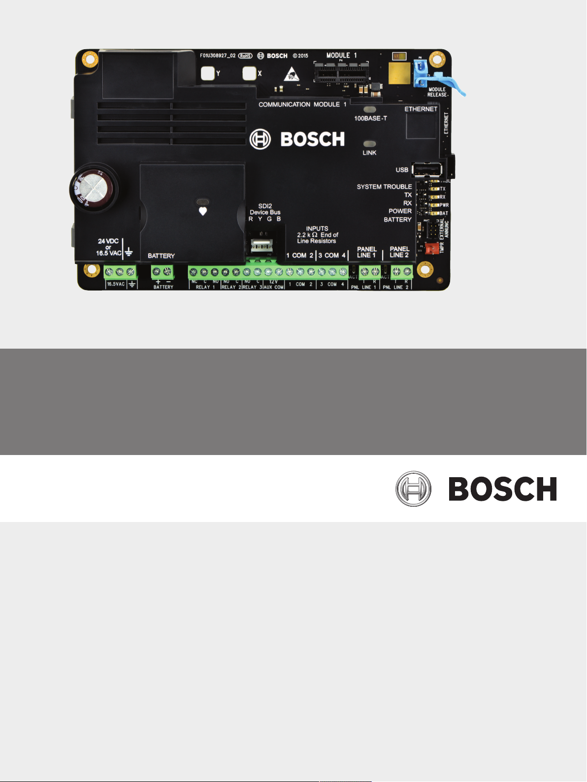
The B465 Conettix Universal Dual Path Communicator (referred to as the B465) links the
control panel PSTN digital dialer and/or dry contact inputs from a control panel to an IP
connection (Ethernet or Cellular) to the D6600 or D6100i Communication Receiver/Gateway
through an internet connection.
There is no need to change the control panel’s reporting format for IP communications when
the B465 is installed. The B465 embeds the reports from the control panel into Conettix IP
reports. The embedded reports are in the same reporting format they were received in. The
B465 sends its internal status in Contact ID reports embedded Conettix IP reports.
When the control panel’s PSTN dialer sends a report, the B465 simulates a public switched
telephone network (PSTN) to receive the report. The B465 decodes the control panel PSTN
dialer report and then sends the decoded report to the Conettix D6600, D6100IPv6, or D6100i
Communication Gateway/Receiver (referred to as the central station receiver) using an IP
connection and the Bosch Conettix IP protocol. When the central station receiver receives the
report, it sends back an acknowledgement report to the B465 through the Conettix IP
protocol. The B465 sends the acknowledgement report to the connected control panel
through the simulated PSTN connection. This process maintains true end-to-end security.
B465 connections:
– Ethernet connects to the network
– 4 programmable inputs
– 3 programmable outputs (dry contact relays) (use to transmit B465 status to the control
panel, if required)
– control panel phone lines to B465 panel line 1 and panel line 2 terminals
– B44x Plug-in Cellular Communicator module (optional)
– B46 External Annunciator (optional)
2.1 About documentation
Copyright
This document is the intellectual property of Bosch Security Systems, Inc. and is protected by
copyright. All rights reserved.
Trademarks
All hardware and software product names used in this document are likely to be registered
trademarks and must be treated accordingly.
2.2 Bosch Security Systems, Inc. product manufacturing dates
Use the serial number located on the product label and refer to the Bosch Security Systems,
Inc. website at http://www.boschsecurity.com/datecodes/.
2.3 Installation workflow
To install and configure the B465, use the workflow below and follow in order from top to
bottom.
!
Caution!
Always power down the B465 when making connections. To power down the B465, unplug
the transformer and disconnect the battery.

Conettix Universal Dual Path Communicator Introduction | en 9
Bosch Security Systems, Inc. Installation and Operation Manual 2017.11 | 05 | F.01U.311.207
Installation workflow checklist
Plan the installation.
Unpack the device contents
Install the enclosure (Refer to Mount the enclosure, page 15)
Mount the B465 into the enclosure (Refer to Install the B465 in the enclosure, page 17)
Mount the B46 (module and cover) into the enclosure (Refer Insert B46 LED cover
(optional), page 16)
Insert the plug-in communicator into the B465 (if required) (Refer to Install the cellular
plug-in communicator module (optional), page 17)
Wire the B465 to a compatible control panel (Refer to Wiring installation, page 19)
Wire the relays (outputs)
Power up the system
Install a communication program (if required) (Refer to Communications)
Configure the communication module
Verify LED activity (Refer to B465 LED status indicators, page 80)
Review signal strength on the cellular communicator (if required). Refer to your cellular
communicator Installation Guide for more information on signal strength.
Installation is complete

10 en | System overview Conettix Universal Dual Path Communicator
2017.11 | 05 | F.01U.311.207 Installation and Operation Manual Bosch Security Systems, Inc.
3 System overview
Refer to the figure below for the complete B465 system configuration.
1
10
11
2
8
6
5
7
9
4
TMPR
BAT
ETHERNET
EXTERNAL
ANNUNC
X
MODULE 1
Y
MODULE
RELEASE
1 COM 2 PNL LINE 2
3 COM 4 PNL LINE 1
C NO
RELAY2
+ BAT -18VAC
NO C NC
RELAY1
TRBL
TX
RX
AC
PANEL
LINE 2
USB
ETHERNET
100BASE-T
LINK
COMMUNICATION MODULE 1
3 COM 41 COM 2
R Y G B
SDI2
Device Bus
18 VAC BATTERY
PANEL
LINE 1
BATTERY
AC
RX
TX
SYSTEM TROUBLE
INPUTS
2.2 k End of
Line Resistors
C NO
RELAY3
12V
AUX COM
3
Figure3.1: System connection overview
Callout ー Description Callout ー Description
1 ー Intrusion/fire control panel 7 ー Cellular communication to cellular carrier
2 ー Phone line connections (phone line 1
and phone line 2)
8 ー Cellular carrier network
3 ー B465 Conettix Universal Dual Path
Communicator
9 ー Conettix receiver/gateway (D6100IPv6
shown)
4 ー B44x plug-in cellular communicator 10 ーConettix receiver/gateway (D6600
shown)
5 ー Ethernet connection (RJ-45 cable
connection to the LAN/WAN)
11 ー Monitoring center automation
(classified per UL 1981)
6 ー Internet/Cloud
3.1 B465 overview
The B465 allows any fire and intrusion control systems with PSTN dialers and/or dry contact
inputs to communicate with Bosch central station receivers over Ethernet or cellular networks
through IP. This allows customers using control panels developed before the introduction of
networking and cellular to eliminate costly phone lines and gain some of the modern
performance that IP networking enables.
The B465 is compatible with the following standard reporting formats:
– Modem II
– Modem IIe
– Modem IIIa2
– Ademco Contact ID (SIA DC-05) +10 digit account codes
– Pulse 3/1, 3/1 Checksum (2300 Hz ACK Tone)
– Pulse 3/1, 3/1 Checksum (1400 Hz ACK Tone)
– Pulse 4/2 (2300 Hz ACK Tone)

Conettix Universal Dual Path Communicator System overview | en 11
Bosch Security Systems, Inc. Installation and Operation Manual 2017.11 | 05 | F.01U.311.207
– Pulse 4/2 (1400 Hz ACK Tone)
– SIA (SIA8, SIA20)
The B465 links the control panel’s PSTN dialer to the internet and then to one of the Bosch
Conettix receivers. The B465:
– Connects with the control panel PSTN dialer (through the B465 panel line terminals) or
the control panel relay outputs connected to the B465 inputs.
– Embeds alarm reports in Conettix IP reports and sends them to a Conettix D6600, D6100i
or D6100IPv6 Communications Receiver/Gateway through an IP network.
– The Conettix receiver replies to the B465 with an acknowledgement report.
– The B465 sends an acknowledgement back to the control panel through the PSTN
interface which completes the signal transmission
Refer to the following illustration for component locations on the B465.
2
3
7
1315
1
4
5
8
9
6
10
11
TMPR
BAT
ETHERNET
EXTERNAL
ANNUNC
X
MODULE 1
Y
MODULE
RELEASE
1 COM 2 3 COM 4 T R
PNL LINE 1
C NO
OUTPUT
2
+ BAT -- +
NO C NC
OUTPUT 1
TRBL
TX
RX
AC
PANEL
LINE 2
USB
ETHERNET
100BASE-T
LINK
COMMUNICATION MODULE 1
3 COM 41 COM 2
R Y G B
SDI2
Device Bus
24 VDC
or
16.5VAC BATTERY
PANEL
LINE 1
BATTERY
AC
RX
TX
SYSTEM TROUBLE
INPUTS
2.2 k End of
Line Resistors
C NO
OUTPUT
3
12V
AUX COM
16 12
14
T R
PNL LINE 2
16.5VAC
Figure3.2: Module overview
Call out - description
1
- Plug-in stabilizing holes (X,Y) - the plug-in cellular communicator modules compatible
with the B465 use the X hole.
2
- Plug-in module connector - for compatible plug-in cellular communicator modules.
3
- Plug-in module retention clip - pull the tab towards you to install or release plug-in
cellular communicator modules.
4
- On-board Ethernet connector - for wired IP communication with D6600 or D6100IPv6
central station receiver.
5
- USB connector - for temporary connection to a computer for B465 configuration, status,
and diagnotics.
6
- Status LEDs (SYSTEM TROUBLE, TX, RX, POWER, BATTERY) - these LEDs show system
troubles, Ethernet transmit (TX) and receive (RX) traffic, and the status of the primary power
source and the battery.

12 en | System overview Conettix Universal Dual Path Communicator
2017.11 | 05 | F.01U.311.207 Installation and Operation Manual Bosch Security Systems, Inc.
7
- EXTERNAL ANNUNC connector - for the optional B46 External annunciator. The B46 uses
LEDs to show System Trouble (TRBL), Power (PWR), and Battery (BAT). The B46 is
compatible with the B10, and D8103 enclosures. The LEDs are visisble through a knockout in
the enclosure door.
8
- TMPR connector - for the ICP-EZTS Tamper Switch. Use this tamper switch on B10(R)
and B11(R) enclosures. The default configuration for this connecter is disabled. Commercial
Burger installations require an enclosure tamper.
9
- PANEL LINE 1, PANEL LINE 2 terminals - for connection to the phone line terminals of
supported control panels and fire control panels for the dialer capture function.
10
- 1 COM 2, 3 COM 4 terminals - for inputs 1 to 4. Connect to dry contact outputs on the
control panel to communicate alarm events and control panel status to the B465. The B465
sends an applicable report to the central station receiver.
11
- 12V AUX/COM terminal - provides 0.5 A of power at 12 VDC for auxiliary devices
(Special Application 9.9 - 13.8 V).
12
- OUTPUT (RELAY) 1, OUTPUT (RELAY) 2, OUTPUT (RELAY) 3 terminals - Output 1 is a
Form C dry contact relay rated at 30 VDC. 0.5 A. Output 2 and Output 3 are Form A dry
contact relays rated at 30 VDC, 0.1 A. All three outputs are configurable.
13
- Heartbeat LED - shows the operational status of the B465.
14
- BATTERY terminals- connect a 12 V 7-18 Ah Lead Acid battery. The battery is the
secondary (backup) power source for the B465.
15
- Earth Ground terminal - Used for earth ground transient protection and reduced
emissions.
16
- 24 VDC or 16.5 VAC terminals - connect the primary power supply for the B465. You can
use 24 VDC from a UL listed fire control panel or power supply. Or you can use a D1640 plug-
in transformer, D1640-CA plug-in transformer, or D1640-120WI wired-in transformer. These
transformers have a rating of 16.5 VAC, 40 VA.
Notice!
Commercial Fire requirement
Commercial Fire applications require that you install a D8004 Transformer Enclosure if you
are using either the D1640 or D1640-CA plug-in transformers.
3.2 PSTN reporting format compatibility
The B465 is suitable for use with of the following standard digital dialer formats:
– Modem II
– Modem IIe
– Modem IIIa2
– Ademco Contact ID (SIA DC-05) +10 digit account codes
– Pulse 3/1, 3/1 Checksum (2300 Hz ACK Tone)
– Pulse 3/1, 3/1 Checksum (1400 Hz ACK Tone)
– Pulse 4/2 (2300 Hz ACK Tone)
– Pulse 4/2 (1400 Hz ACK Tone)
– SIA (SIA8, SIA20)
3.2.1 Phone line voltage
The B465 simulates conventional phone lines to the control panel. The B465 supplies a
constant phone voltage of 28 VDC (control panel dialer on hook) to satisfy the control panel's
phone line monitor. The B465 phone voltage is 3 to 8 VDC when the control panel attempts to
communicate (off hook).

Conettix Universal Dual Path Communicator System overview | en 13
Bosch Security Systems, Inc. Installation and Operation Manual 2017.11 | 05 | F.01U.311.207
You can configure the B465 to remove the phone line voltage when there is a communication
failure between the B465 and the central station receiver. Removing the phone line voltage
causes a communication trouble (phone line trouble) to occur at the control panel.
3.3 IP communication
The B465 uses its built-in Ethernet connection, and a Conettix Plug-in cellular module (B44x)
to send reports to the central station receiver. The system routes event reports to the primary
and secondary destinations using Ethernet or cellular communication, depending on
configuration.
3.4 B46 overview (optional)
The B46 is an optional module that provides external B465 LED and sounder status when
installed in a supported enclosure. The module has 3 LEDs (System Trouble, Power, and
Battery) which illuminate through the B46 LED cover. The LED cover snaps into a knockout in
the enclosure door. The B46 fits in the B10/B10R, D8103 enclosure. Refer to the following
figure for component locations.
BOSCH
1
5
3
2
4
6
Figure3.3: B46 module overview
Callout ー Description
1 ー Sounder
2 ー SYSTEM TROUBLE LED
3 ー POWER LED
4 ー BATTERY LED
5 ー 3-hole mounting pattern
6 ー B46/B465 cable connection

14 en | System overview Conettix Universal Dual Path Communicator
2017.11 | 05 | F.01U.311.207 Installation and Operation Manual Bosch Security Systems, Inc.
1
3
2
BOSCH
Figure3.4: B46 LED cover (B10 enclosure shown)
Callout ー Description
1 ー B10 Medium Control Panel Enclosure, door closed
2 ー B46 LED cover
3 ーEnclosure lock (D101 supplied separately)
For LED patterns, refer to B465 LED status indicators, page 80.

Conettix Universal Dual Path Communicator Installation | en 15
Bosch Security Systems, Inc. Installation and Operation Manual 2017.11 | 05 | F.01U.311.207
4 Installation
Perform the following steps to install the module.
Notice!
B46 External Annunciator installation
Refer to the B46 External Annunciator Installation Guide (P/N: F01U312441) prior to installing
the enclosure for B465 module. There is a specific installation sequence you must follow to
avoid damaging the B46 module during the installation process.
4.1 Remove enclosure knockouts
Refer to Figure 4.1 below for knockout locations.
!
Caution!
Insert conduits into the enclosure knockout areas when running wire or cabling to reduce
wire/cable damage.
4.2 Mount the enclosure
Mount one of the following enclosures in the desired location to meet desired UL
requirements:
– B10 Medium Control Panel Enclosure (white)
– B10R Medium Control Panel Enclosure (red)
– B11 Small Control Panel Enclosure (white)
– B11R Small Control Panel Enclosure (red)
– D8103 Universal enclosure (this enclosure requires the B12 mounting plate)
– D8108A Attack Resistant Enclosure (this enclosure requires the B12 mounting plate)
Installing the enclosure:
1. Remove any knockouts prior to installing the module.
2. Mount the enclosure in the desired location. Use all enclosure mounting holes. Refer to
the mounting instructions supplied with the selected enclosure.
3. Pull any necessary wires/phone lines into the enclosure.
Notice!
Electromagnetic interference (EMI) can cause problems on long wire runs

16 en | Installation Conettix Universal Dual Path Communicator
2017.11 | 05 | F.01U.311.207 Installation and Operation Manual Bosch Security Systems, Inc.
1 2
3
11
1
2
Figure4.1: Enclosure mounting (B10 shown)
Callout ー Description
1 ー Enclosure mounting holes (4)
2 ー 3-hole mounting locations (3)*
3 ー Tamper switch mounting locations
*Use the upper, right-hand 3-hole mounting location for installing the optional B46 module in
the enclosure so it lines up with the enclosure door hole.
4.3 Insert D101 lock (optional)
Refer to the instructions provided with the D101 for installation.
Notice!
Commercial fire requirement
The D101 lock is required for commercial fire installations.
4.4 Insert B46 LED cover (optional)
The B46 has an LED cover allowing users to view the B465 LED status indications outside the
enclosure.
1. Punch out the enclosure knockout area.
2. Insert the plastic LED cover into the knockout.
3. Snap the cover into place.
4. Make sure the cover is secure.
For more information, refer to the B46 Install Guide for more information.

Conettix Universal Dual Path Communicator Installation | en 17
Bosch Security Systems, Inc. Installation and Operation Manual 2017.11 | 05 | F.01U.311.207
4.5 Install the B465 in the enclosure
Refer to the B465 Quick Start Guide for more information.
Perform the following to install the module.
!
Warning!
The module is static sensitive. Touch earth ground before handling the circuit board to
discharge any static electricity from your body. Use a grounding strap while installing the
circuit board.
4.5.1 Mount the B46 (optional)
Refer to the B46 Install Guide for more information.
4.5.2 Connect earth ground
To help prevent damage from electrostatic discharges or other transient electrical surges,
connect the system to earth ground before making other connections. The icon indicates the
earth ground terminal. Use a recommended earth ground reference, such as a grounding rod
or a metal cold water pipe. Make the connection using 14 AWG (1.8 mm) to 16 AWG (1.5 mm)
wire.
Notice!
Do not use telephone or electrical ground for the earth ground connection. Do not connect
other control panel terminals to earth ground.
!
Caution!
Avoid electrostatic discharge. Always touch the earth ground connection with the icon first,
before beginning work on the control panel.
Notice!
In ground fault enabled systems, you might cause a ground fault when connecting a computer
to the B465 for programming.
4.6 Install the cellular plug-in communicator module (optional)
For cellular communication, use one of the following:
– B440 Conettix Plug-in Cellular Communicator (3G Verizon, US only)
– B441 Conettix Plug-in Cellular Communicator (Verizon, US only)
– B442 Conettix Plug-in GPRS Cellular Communicator (outside the USA where approved)
– B443 Conettix Plug-in HSPA+ Cellular Communicator (where approved)
– B444 Conettix Plug-in LTE Cellular Communicator (Verizon, US only)
Install the plug-in module
1. Power down the B465.
2. Insert the plug-in module into plug-in stabilizing hole X, and then into the plug-in module
connector. Continue pressing the module into the connector until the retention clip
engages. Refer to callouts 1, 2, and 3 in B465 overview, page 10.

18 en | Installation Conettix Universal Dual Path Communicator
2017.11 | 05 | F.01U.311.207 Installation and Operation Manual Bosch Security Systems, Inc.
3. Route the antenna cable through a wire knockout in the top of the enclosure.
4. Connect the antenna to the threaded connector on the plug-in module.
5. Secure the antenna cable to the outside of the enclosure.
Notice!
Mount antenna on metal surface to improve weak signal
If the signal to the plug-in cellular module is weak, place the antenna on top of a metal
surface that has a radius of 10.16 cm (4 in.) or larger to improve performance.
TMPR
BAT
ETHERNET
EXTERNAL
ANNUNC
X
MODULE 1
Y
MODULE
RELEASE
1 COM 2 3 COM 4 T R
PNL LINE 1
C NO
RELAY2
16.5VAC
NC C NO
RELAY1
TRBL
TX
RX
PWR
PANEL
LINE 2
USB
ETHERNET
100BASE-T
LINK
COMMUNICATION MODULE 1
3 COM 41 COM 2
R Y G B
SDI2
Device Bus
BATTERY
PANEL
LINE 1
BATTERY
POWER
RX
TX
SYSTEM TROUBLE
INPUTS
2.2 k End of
Line Resistors
C NO
RELAY3
12V
AUX COM
T R
PNL LINE 2
24 VDC
or
16.5 VAC
+ -
BATTERY
Figure4.2: Cellular plug-in module

Conettix Universal Dual Path Communicator Installation | en 19
Bosch Security Systems, Inc. Installation and Operation Manual 2017.11 | 05 | F.01U.311.207
4.7 Wiring installation
Refer to the following sections for detailed wiring information.
4.7.1 System wiring
You can use the B465 with a variety of intrusion and fire control panels that support the
B465’s compatible protocols.
TMPR
BAT
ETHERNET
EXTERNAL
ANNUNC
X
MODULE 1
Y
MODULE
RELEASE
1 COM 2 3 COM 4 T R
PNL LINE 1
C NO
RELAY 2
16.5VAC
NC C NO
RELAY 1
TRBL
TX
RX
PWR
PANEL
LINE 2
USB
ETHERNET
100BASE-T
LINK
COMMUNICATION MODULE 1
3 COM 41 COM 2
R Y G B
SDI2
Device Bus
BATTERY
PANEL
LINE 1
BATTERY
POWER
RX
TX
SYSTEM TROUBLE
INPUTS
2.2 k End of
Line Resistors
C NO
RELAY 3
12V
AUX COM
T R
PNL LINE 2
24 VDC
or
16.5 VAC
54
6
7
8
9
10
1
2
+_
+-
BATTERY
3
11
Figure4.3: System wiring
Callout ー Description Callout ー Description
1 ー RJ-45 modular jack for Ethernet IP
communications (optional)
7 ーProgrammable output relays (Relay 1,
Relay 2, Relay 3)
2 ー Connector for External Annunciator
(connected to optional B46)
8 ー12 VDC lead-acid battery (7 to 18 Ah)
3 ー To tamper switch 9 ーTo earth ground
4 ーPhone Line 1/2 (to control panel
terminals if required)
10 ーD1640 plug-in transformer, D1640-CA
plug-in transformer, D1640-120WI wired-in
transformer or optional 24 VDC from a UL
listed fire control panel or power supply
5 ーFour EOL input loops 11 ーSDI2 device bus connector (for future
use)
6 ー12V AUX/COM terminals for 12 VDC
auxiliary power (optional output power
source, Special Application 9.9 to 13.8 V)

20 en | Installation Conettix Universal Dual Path Communicator
2017.11 | 05 | F.01U.311.207 Installation and Operation Manual Bosch Security Systems, Inc.
Notice!
For ground fault detection, connect the common terminals of the FACP and the B465
Connect the common terminal of the FACP (Fire Alarm Control Panel) auxiliary power to the
common (COM) terminal of the B465 auxiliary power. Do not connect to earth ground on the
FACP or the B465.
Other manuals for B465
2
Table of contents
Other Bosch Cell Phone manuals

Bosch
Bosch GSM 509 User manual

Bosch
Bosch GMS 509 DUAL User manual

Bosch
Bosch D6412 User manual

Bosch
Bosch QSM 1800 User manual

Bosch
Bosch B465 User manual

Bosch
Bosch Conettix ITS-300GSM User manual

Bosch
Bosch ITS-DX4020-G Operating instructions

Bosch
Bosch GSM 909 DUAL S User manual

Bosch
Bosch SAFECOM SC3100 Quick start guide

Bosch
Bosch WORLD 718 User manual