Bosch CONETTIX B444-A2 User manual

CONETTIX Cellular Communicators
B444‑A2/B444‑V2
en Installation manual


CONETTIX Cellular Communicators Table of contents | en 3
Bosch Security Systems B.V. Installation manual 2022.08 | 01 | F.01U.408.422
Table of contents
1Cellular module introduction 4
1.1 About documentation 4
1.2 Bosch Security Systems B.V. product manufacturing dates 4
2Component overview 6
3Installation 8
3.1 Install the antenna 8
3.2 Install the communicator 9
3.3 Remove the communicator 10
4Diagnostic LED descriptions 11
5Configuration 12
5.1 Activating the cellular communicator 12
6Specifications 13

4en | Cellular module introduction CONETTIX Cellular Communicators
2022.08 | 01 | F.01U.408.422 Installation manual Bosch Security Systems B.V.
1 Cellular module introduction
This document contains supplemental information needed to install the Conettix Plug-in
Cellular communication modules.
This installation manual contains:
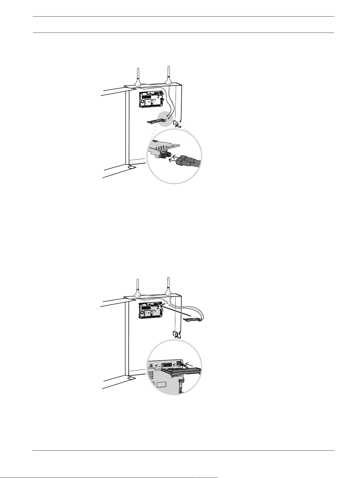
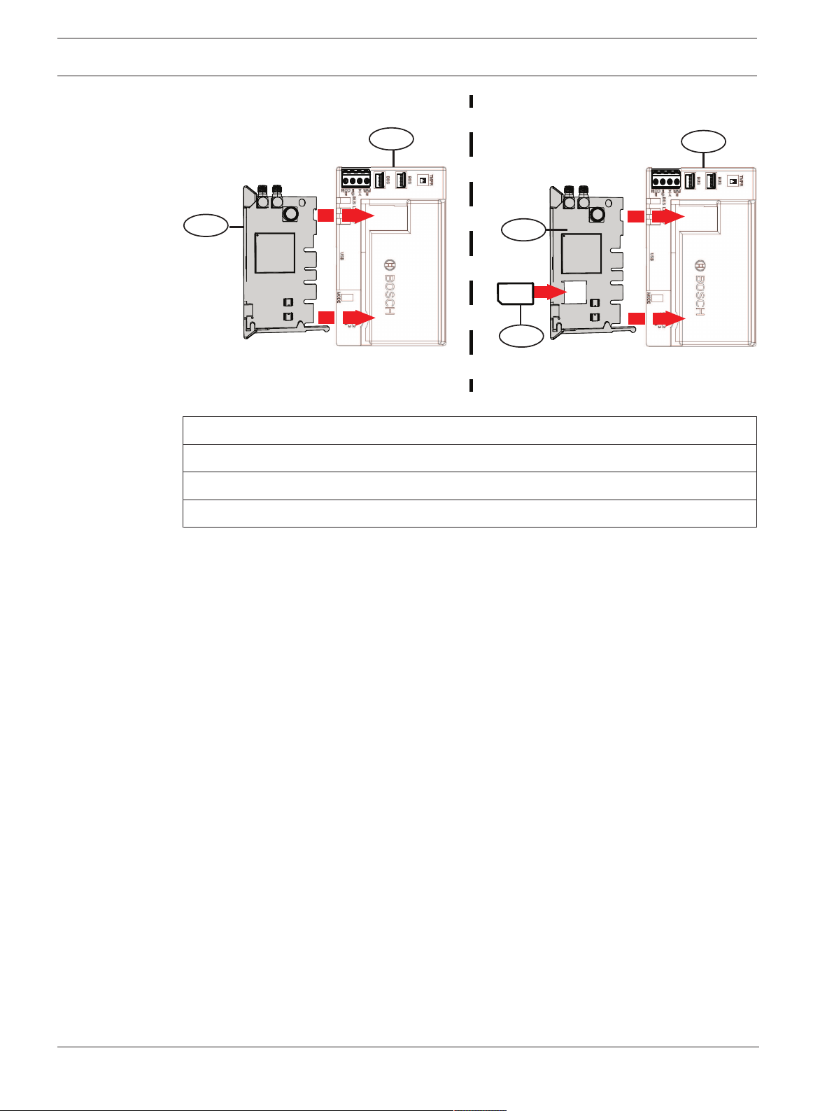
– Component location overview.
– Installation workflows.
– Diagnostic LED descriptions.
– Configuration.
– Specifications.
Federal Communications Commission
Changes or modifications not expressly approved by the party responsible for compliance
could void the user's authority to operate the equipment.
Note: This equipment has been tested and found to comply with the limits for a Class B digital
device, pursuant to Part 15 of the FCC Rules. These limits are designed to provide reasonable
protection against harmful interference in a residential installation. This equipment generates,
uses, and can radiate radio frequency energy and, if not installed and used in accordance with
the instructions, may cause harmful interference to radio communications. However, there is
no guarantee that interference will not occur in a particular installation. If this equipment does
cause harmful interference to radio or television reception, which can be determined by
turning the equipment off and on, the user is encouraged to try to correct the interference by
one or more of the following measures:
- Reorient or relocate the receiving antenna.
- Increase the separation between the equipment and receiver.
- Connect the equipment into an outlet on a circuit different from that to which the receiver is
connected.
- Consult the dealer or an experienced radio/TV technician for help.
This equipment has been verified to comply with the limits for a class B computing device,
pursuant to FCC Rules. In order to maintain compliance with FCC regulations, shielded cables
must be used with this equipment. Operation with non-approved equipment or unshielded
cables is likely to result in interference to radio and TV reception. The user is cautioned that
changes and modifications made to the equipment without the approval of manufacturer
could void the user’s authority to operate this equipment.
1.1 About documentation
Copyright
This document is the intellectual property of Bosch Security Systems B.V. and is protected by
copyright. All rights reserved.
Trademarks
All hardware and software product names used in this document are likely to be registered
trademarks and must be treated accordingly.
Available Online Resources: Instructional & Overview Videos
1.2 Bosch Security Systems B.V. product manufacturing dates
Use the serial number located on the product label and refer to the Bosch Security Systems
website at http://www.boschsecurity.com/datecodes/.
The following image shows an example of a product label and highlights where to find the
manufacturing date within the serial number.

CONETTIX Cellular Communicators Cellular module introduction | en 5
Bosch Security Systems B.V. Installation manual 2022.08 | 01 | F.01U.408.422

6en | Component overview CONETTIX Cellular Communicators
2022.08 | 01 | F.01U.408.422 Installation manual Bosch Security Systems B.V.
2 Component overview
Cellular plug-in communicators provide IP communications over supported cellular networks
by directly connecting the communicator into a control panel or into an additional module
such as the CONETTIX Plug-in Communicator Interface or the CONETTIX Universal Dual Path
Communicator modules. All communicators come with a SIM card holder.
12
4
5
6
1
3
7
Callout - Description
1 - Module handle and support leg
2 - SIM card holder
3 - LEDs
4 - Threaded female SMA antenna connector (secondary)
5 - Threaded female SMA antenna connector (primary)
6 - Plug-in module retention clip opening
7 - PCM metal contacts
i
Notice!
Connections to both antenna connectors (secondary and primary) must be installed using the
supplied antennas or an extended antenna (sold separately). Failure to do so might cause
poor signal strength.
When using an external antenna such as the Bosch Multiband Antenna (B40-P, B40-MB25 or
B40-MB50) connect the cable to the primary connector of the cellular module. You must also
connect the supplied antenna to the secondary antenna connection. Failure to do so may
result in poor service and dropped signals or connection.

CONETTIX Cellular Communicators Component overview | en 7
Bosch Security Systems B.V. Installation manual 2022.08 | 01 | F.01U.408.422
1
2
3
Figure2.1:
1 Cellular communicator module
2 Primary antenna connection port
3 B40-P/MB25/MB50 external antenna
1. Connect antenna wire to the B40-P/MB25/MB50 antenna port (callout #3).
2. Connect other end of B40-P/MB25/MB50 antenna wire to primary antenna port on the
cellular communicator module (callout #2).

8en | Installation CONETTIX Cellular Communicators
2022.08 | 01 | F.01U.408.422 Installation manual Bosch Security Systems B.V.
3 Installation
When installing the communicator into a supporting module or control panel, refer to the
compatible documentation for more information.
!
Caution!
Remove all power (AC and battery) before making any connections. Failure to do so might
result in personal injury and/or equipment damage.
3.1 Install the antenna
1. Put the magnetic antenna on top of the enclosure, or vertically on another metal surface.
2. Put the antenna cable through a knockout.
3. Connect the antenna cable to the module.
4. Make sure the antenna cable is inside the enclosure.
i
Notice!
For proper spacing, the antennas should be placed at either corner of the enclosure.

CONETTIX Cellular Communicators Installation | en 9
Bosch Security Systems B.V. Installation manual 2022.08 | 01 | F.01U.408.422
3.2 Install the communicator
Control panel/universal dual path communicator installation
1. Put the support leg into the support hole labeled X.
2. Align the PCB metal contacts with the on-board connector.
3. Push the module into place. The retention clip snaps closed and secures the module in
place.
Plug-in communicator interface installation
1. Insert the communicator into the slot of the plug-in communicator interface.
2. Push in until you feel it "click" into place.

10 en | Installation CONETTIX Cellular Communicators
2022.08 | 01 | F.01U.408.422 Installation manual Bosch Security Systems B.V.
3
1
2
3
2
Figure3.1: Communicator installation (B450 shown)
Callout - Description
1 - SIM card insertion (if applicable)
2 - Communicator
3 - Plug-in communicator interface
3.3 Remove the communicator
1. Hold the plug-in module retention clip open.
2. Hold the top corners of the module support handle with your other hand.
3. Pull the module out.

CONETTIX Cellular Communicators Diagnostic LED descriptions | en 11
Bosch Security Systems B.V. Installation manual 2022.08 | 01 | F.01U.408.422
4 Diagnostic LED descriptions
At power up, all communicator LEDs activate for several seconds, indicating proper insertion.
The Signal LEDs then turn off until the module registers on the cellular network. Registering a
new module might take up to 2 min.
Check the LED display to ensure a good signal strength level, and adjust the antenna location
as required. The signal strength LEDs momentarily turn off to indicate the module has
measured and updated the signal strength status.
Signal strength
Flash pattern Function
Red Indicates an unacceptable signal strength
level.
Yellow Indicates a marginal signal strength level.
Green (1 light) Indicates a good signal strength level.
Green (2 lights) Indicates a very good signal strength level.
No LED Indicates that the module has not acquired a
tower yet.
Table4.1: Signal strength LED descriptions
STATUS
Flash pattern Function
Flashes once every 1 sec (blue) Normal State: Indicates normal operation.
On Steady (blue) Communication Error State: Indicates the
communicator is unable to communicate on
the cellular network.
Off LED Trouble State: Indicates communicator is
not powered, or some other trouble condition
prohibits the communicator from controlling
the STATUS LED. (Check for proper
installation.)
Table4.2: STATUS LED descriptions

12 en | Configuration CONETTIX Cellular Communicators
2022.08 | 01 | F.01U.408.422 Installation manual Bosch Security Systems B.V.
5 Configuration
Communicator programming is done through the compatible control panel, plug-in
communicator interface, or universal dual path communicator. Refer to the documentation of
these devices or remote programming software help for more information. For Bosch Cellular
account status and management, use RPS or the online service portal (go to http://
www.conettix.com/plansandrecommendedsettings and click on the Cellular Portal Login link).
Configure network alarm communication routes and settings in the control panel. Cellular
carrier specific settings such as Access Point Name and SIM card security can also be
programmed through the control panel or Conettix Plug-in Communicator Interface.
5.1 Activating the cellular communicator
The cellular communicator requires a valid Bosch Installer Services account and must be
activated with a valid cellular plan for proper usage. If your device requires activation:
– contact Bosch Installer Services by submitting a support ticket via the Bosch Cellular
Portal email at: [email protected], or
– call Bosch Installer Services (800-289-0096).
Please provide the IMEI and ICCID numbers found on the box or on the communicator for
proper activation.

CONETTIX Cellular Communicators Specifications | en 13
Bosch Security Systems B.V. Installation manual 2022.08 | 01 | F.01U.408.422
6 Specifications
Refer to the communicator graphical installation manuals for communicator specification
information.

14 | Specifications CONETTIX Cellular Communicators
2022.08 | 01 | F.01U.408.422 Installation manual Bosch Security Systems B.V.


Bosch Security Systems B.V.
Torenallee 49
5617 BA Eindhoven
Netherlands
www.boschsecurity.com
© Bosch Security Systems B.V., 2022
202208181601
Building solutions for a better life.
This manual suits for next models
2
Table of contents
Other Bosch Cell Phone manuals

Bosch
Bosch B465 User manual

Bosch
Bosch GSM 509 User manual

Bosch
Bosch D7212G User manual

Bosch
Bosch GSM 909 DUAL S User manual

Bosch
Bosch GSM-Com 608 User manual

Bosch
Bosch Doro Secure 680 User manual

Bosch
Bosch B430 User manual

Bosch
Bosch ITS-DX4020-G Operating instructions

Bosch
Bosch B442 User manual

Bosch
Bosch GSM 1900 User manual

Bosch
Bosch B441 User manual

Bosch
Bosch D6412 User manual

Bosch
Bosch D9068 Quick start guide

Bosch
Bosch Conettix ITS-300GSM User manual

Bosch
Bosch B465 User manual

Bosch
Bosch ITS-DX4020-G User manual

Bosch
Bosch DS7240-UK User manual

Bosch
Bosch QSM 1800 User manual

Bosch
Bosch B440 User manual

Bosch
Bosch GSM 908 User manual