2
7
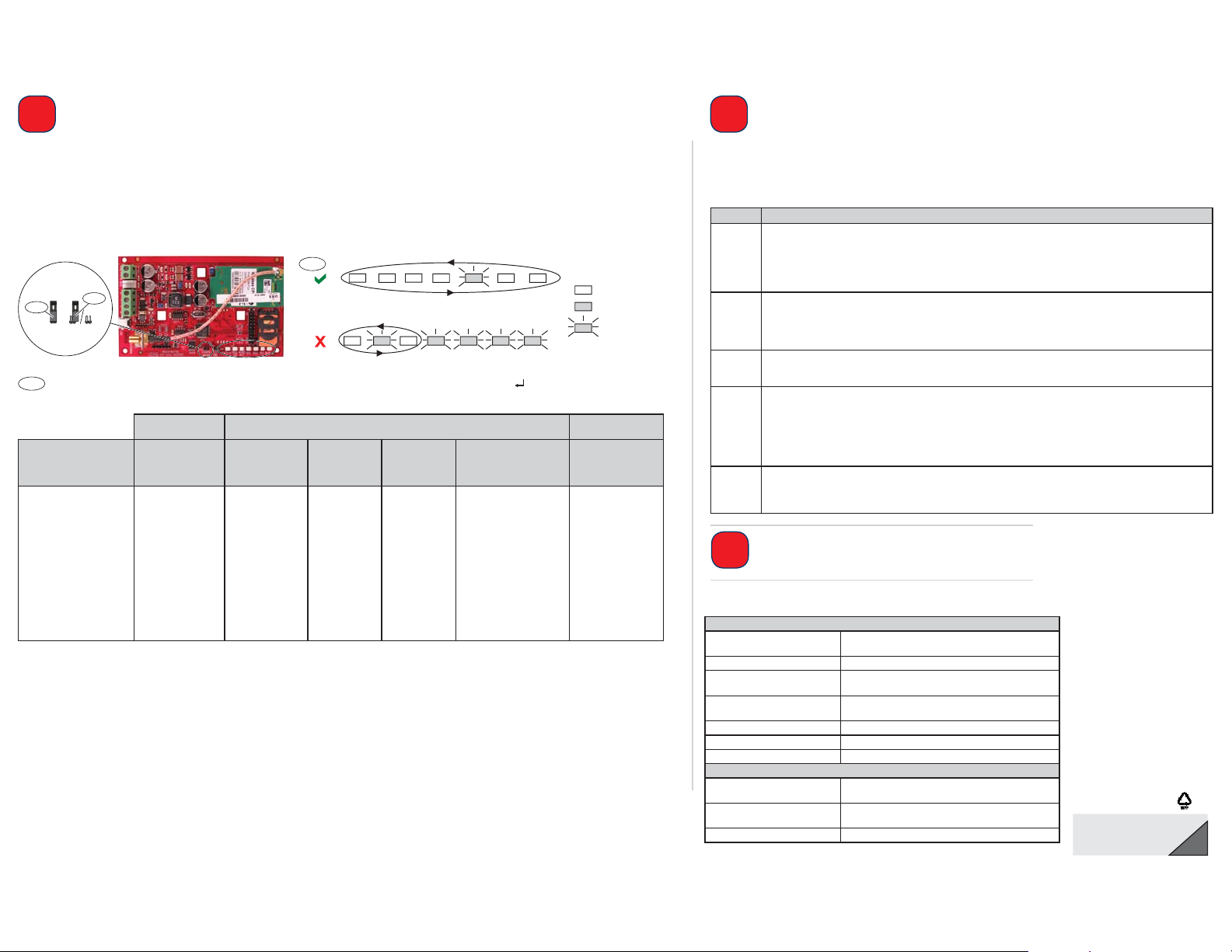
SMS =
STATUS CELL
IP
AUDIO
ACT
SS1 SS2 SS3 BUS
SMS =
STATUS CELL
IP
AUDIO
ACT
SS1 SS2 SS3 BUS
4
CONFIG
MODE
OFF
ON
1
5
= LED On
= LED Off
= LED Flashing
8
2
© 2012 Bosch Security Systems, Inc.
2012.10
F01U274446-02 en
Any of these characters is acceptable to separate command lines. Refer to your cellular phone’s documentation for available characters.
Configure the ITS-DX4020-G
Separate each command line in the SMS with either a line feed <LF>, a carriage return <CR> or < ENTER>, or a semi-colon (;).
USB Configuration
For complete USB configuration instructions, refer to the Conettix ITS-DX4020-G Installation and Operation Guide on the supplied CD-ROM.
1. Connect the ITS-DX4020-G to the target PC or laptop with a USB-to-mini-USB cable (not supplied).
2. Download the ITS-DX4020-G.inf file from the supplied CD-ROM and install it on the target PC or laptop.
3. On the ITS-DX4020-G, short the CONFIG MODE jumper pins with the supplied jumper plug.
4. From Windows, start a terminal session (use HyperTerminal or Tera Term).
5. In the terminal session, configure a new virtual serial COM port (for example, COM4):
Baud rate: 9600; Data bits: 8; Parity: None; Stop bits: 1; Flow control: None
6. Press [Enter] on the keyboard. The USB Login window opens.
7. Enter the login password (default: 4020G all uppercase) and press [Enter].
8. Configure the ITS-DX4020-G as needed using USB menu Options 8 (Change Basic Parameters).
The table above shows the parameters that must be set as a minimum.
9. When configuration is complete, select Option 6 (Save and Reboot) from the USB menu to save all changes and to restart the ITS-DX4020-G.
Test the ITS-DX4020-G
Contact the central monitoring station for destination IP address and port number settings. Provide
the central monitoring station with the poll rate setting.
Test the system to ensure that it can send reports from the ITS-DX4020-G to the central monitoring
station in the selected mode of operation.
Installation Complete
Technical Specifications
You can configure the ITS-DX4020-G by sending a text message from your mobile phone or by using the USB interface from a PC or laptop.
SMS (Text Message) Configuration
1. Place the supplied jumper plug across the CONFIG MODE jumper pins.
2. Compose the SMS (see the table below for sample messages).
3. Send the SMS to the phone number assigned to the SIM card in the ITS-DX4020-G.
4. Check the diagnostic LEDs on the ITS-DX4020-G to ensure that the SMS was properly received.
5. When the ITS-DX4020-G is successfully configured, remove the jumper plug from the CONFIG MODE pins. The ITS-DX4020-G restarts.
Dual Wireless Mode IP Over GPRS Mode
PSTN (Contact ID)
Over GSM Mode
ITS-DX4020-G
SMS Settings Easy Series
DS7200V2/
Easy Series/
ICP-CMS8-CHI/ICP-
CMS6-CHI DS7400Xi FPD-7024 GV2/GV3/GV4 Series
For control panels
that support Contact
ID
%1 = Start SMS %1 %1 %1 %1 %1 %1
1 = Password 1=4020G 1=4020G 1=4020G 1=4020G 1=4020G 1=4020G
4 = SIM PIN (if required)
10 = GPRS APN 10=<your APN> 10=<your APN> 10=<your APN> 10=<your APN> 10=<your APN>
11 = GPRS Username
(if required)
12 = GPRS Password
(if required)
14 = Bus Address 14=134 (default) 14=13 14=250 14=88 (92 for GV3/GV4) 14=0
17 = Comm Path 17=2 17=2 17=2 17=2 17=3
! = End SMS ! ! ! ! ! !
Electrical
Operating Current • Standby: 65 mA
• Alarm: 200 mA
Operating Voltage 12 VDC nominal
Maximum Wire Resistance for
Control Panel Connections
1.6 ohms
Maximum Wire Distance • 22 AWG: 30.5 m (100ft)
• 18 AWG: 61 m (200 ft)
Ripple/Noise 200 mVpp maximum
PSTN FSX Port 17 V minimum supplied
Radio GSM Quad band radio; 850 MHz and 1900 MHz
Other
Antenna • Magnetic base omni-directional antenna
• 2.5 m (8.2 ft) cable with SMA connector
SIM Card 3 V/1.8 V SIM (compliant with GSM 11.12
recommendation)
USB Mini-B connector (cable not supplied)
LED Function
STATUS Indicates the overall health of the device.
• ON: Normal operation.
• Flash: A trouble condition exists.
• OFF: No power to the device.
When the LED DIS jumper pins are first shorted, the STATUS LED flashes the firmware version. After that, the STATUS
LED flashes once every 4 sec to indicate that the ITS-DX4020-G is powered up.
CELL IP Indicates the IP connection status.
• ON: The ITS-DX4020-G is connected to the central station receiver through the GPRS network.
• Flash: The ITS-DX4020-G is connected to the GPRS network, but not to the central station receiver.
• OFF: The ITS-DX4020-G is not connected to the GPRS network, or the module is configured for Contact ID over
GSM.
AUDIO ACT Indicates the PSTN connection status.
• ON: The PSTN connection is in use (off-hook).
• OFF: The PSTN connection is not in use (on-hook).
SS1, SS2,
SS3
These LEDs indicate the wireless signal strength of the ITS-DX4020-G.
• Registering on the GSM network: SS1 flashes, SS2 and SS3 OFF
• Unacceptable: All three LEDs are off; or SS1 ON, SS2 and SS3 OFF
• Marginal: SS1 ON, SS2 flashes, SS3 OFF
• Good: SS1 and SS2 ON, SS3 OFF
• Very Good: SS1 and SS2 ON, SS3 flashes
• Excellent: All three LEDS ON
BUS Indicates bus connection status.
• ON: Active communication exists between the ITS-DX4020-G and the control panel.
• Flash: The ITS-DX4020-G is initializing, or a problem exists with the bus connection to the control panel.
• OFF: The ITS-DX4020-G is not configured for bus communication.


