Bosch D7212G User manual

Control/Communicator D7212G
Approved Applications Compliance Guide

D7212G Approved Applications Compliance Guide
Page 2 © 2003 Bosch Security Systems
D7212G
4998138560C
Approved Applications Compliance Guide

D7212G Approved Applications Compliance Guide
D7212G
Page 3© 2003 Bosch Security Systems 4998138560C
Contents
Contents
1.0 Approved Applications Compliance Guide ............................................................................................................................ 5
1.1 Listings and Approvals ......................................................................................................................................................... 5
1.1.1 Fire ............................................................................................................................................................................................ 5
1.1.2 Burglary ................................................................................................................................................................................... 5
1.2 Introduction ............................................................................................................................................................................. 5
1.3 Optional Compatible Equipment ...................................................................................................................................... 5
1.3.1 Burglary Applications ........................................................................................................................................................... 5
1.3.2 Bank Safe and Vault Applications .................................................................................................................................... 5
1.3.3 Fire Applications .................................................................................................................................................................... 5
1.3.4 Enclosures .............................................................................................................................................................................. 6
2.0 System Chart ..........................................................................................................................................................................................7
3.0 System Wiring Diagrams, Issue A ............................................................................................................................................... 9
3.1 D7212G Control/Communicator, 1 of 3 ......................................................................................................................... 9
3.2 D7212G Control/Communicator, 2 of 3 .......................................................................................................................10
3.3 D7212G Control/Communicator, 3 of 3 .......................................................................................................................11
4.0 Current Rating Charts ..................................................................................................................................................................... 13
4.1 Current Rating Chart for Standby Battery Calculations ..........................................................................................13
4.2 Current Rating Chart for D8125Mux ............................................................................................................................. 14
5.0 Standby Battery Requirements ................................................................................................................................................... 15
5.1 Household Burglary and Commercial Burglary ...........................................................................................................15
5.2 Bank Safe and Vault ..........................................................................................................................................................15
5.3 Household Fire Warning Equipment .............................................................................................................................. 15
6.0 Standby Battery Calculation for NFPA 72 Fire Alarm Applications .......................................................................... 16
6.1 Current Chart First .............................................................................................................................................................16
6.2 Household Fire Warning Equipment .............................................................................................................................. 16

D7212G Approved Applications Compliance Guide
Page 4 © 2003 Bosch Security Systems
D7212G
4998138560C
Contents
Figures
Figure 1: D7212G System Wiring Diagram, 1 of 3 .................................................................................................................... 9
Figure 2: D7212G System Wiring Diagram, 2 of 3 .................................................................................................................. 10
Figure 3: D7212G System Wiring Diagram, 3 of 3 ..................................................................................................................11
Tables
Table 1: UL System Chart ................................................................................................................................................................. 7
Table 2: Current Rating Chart for Standby Battery Calculations ......................................................................................... 13
Table 3: Current Rating Chart for D8125MUX ..........................................................................................................................14

D7212G Approved Applications Compliance Guide
D7212G
Page 5© 2003 Bosch Security Systems 4998138560C
1.0 Approved Applications Compliance Guide
1.1 Listings and Approvals
1.1.1 Fire
UL
UnderwritersLaboratoriesliststheD7212GControl/CommunicatorasaControlUnitforHouseholdFireWarning.
CSFM
Approvalbythe California StateFireMarshalforHousehold FireWarning ispending.
1.1.2 Burglary
UL
UnderwritersLaboratoriesliststheD7212GControl/Communicatorfor:
CentralStation,Local,PoliceConnect,BankSafeandVault,MercantileSafeandVault,andGradeAHouseholdSystems.
1.2 Introduction
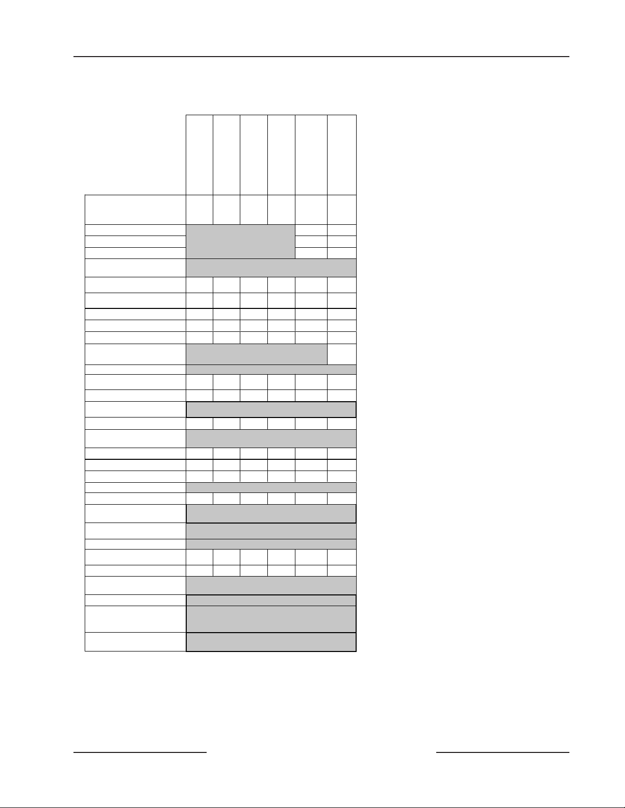
Table1onpage7referencescomponentsevaluatedandlistedbyUnderwritersLaboratoriesforcompatibilitywiththe
control/communicator.Thesecomponentsmeetthebasicsystemrequirementsfortheapplicablestandard.
Section3.0SystemWiringDiagrams,IssueAbeginningonpage9showstherelationshipbetweenthepanelandtheaccessory
componentsreferredtoinTable1onpage7.
1.3 Optional Compatible Equipment
ULListedcomponentsthatdonotrequireevaluationforelectricalcompatibilitycanbeusedinmanyapplicationswhen
installedaccordingtothemanufacturer’sinstructions.
1.3.1 Burglary Applications
ULListedburglaryalarmsensorsthatdonotrequireevaluationforelectricalcompatibilitycanbeusedinburglary
applications.InsomecasesaULListedBoschSecuritySystems interfacemodulemustbeusedinconjunctionwiththe
sensors.Consulttheindividualcomponentspecificationandinstallationdocumentstodeterminesuitability.
Testweekly: ULStandard1023requiresaweeklytestforresidentialburglaryapplications.
1.3.2 Bank Safe and Vault Applications
TheULListedModel5110BellandModel4001-42ExternalLineBalancer(bothmadebyRothenbuhler)mustbeusedfor
thebellandbalancedlinemoduleinbanksafeandvaultapplications.ModificationsmustbemadetotheBoschSecurity
SystemsD8108AenclosuretomeetULStandard681.Seethe9000/9000GSeriesTechnogram:ULCertificatedBankSafeand
VaultApplications(P/N:73-07302-000).
Testbellatarming: ULStandard365 requiresabelltestatarmingforbanksafeandvaultapplications.
1.3.3 Fire Applications
ULListedfireinitiatingdevicesnotrequiringelectricalcompatibilityevaluationcanbeusedinanyapplication.Forexample:
4-wiresmokedetectors,heatdetectors,waterflowswitches,andmanualpullstationsaresuitablefireinitiatingdevices.
Consulttheindividualcomponentspecificationandinstallationdocumentstodeterminesuitability.
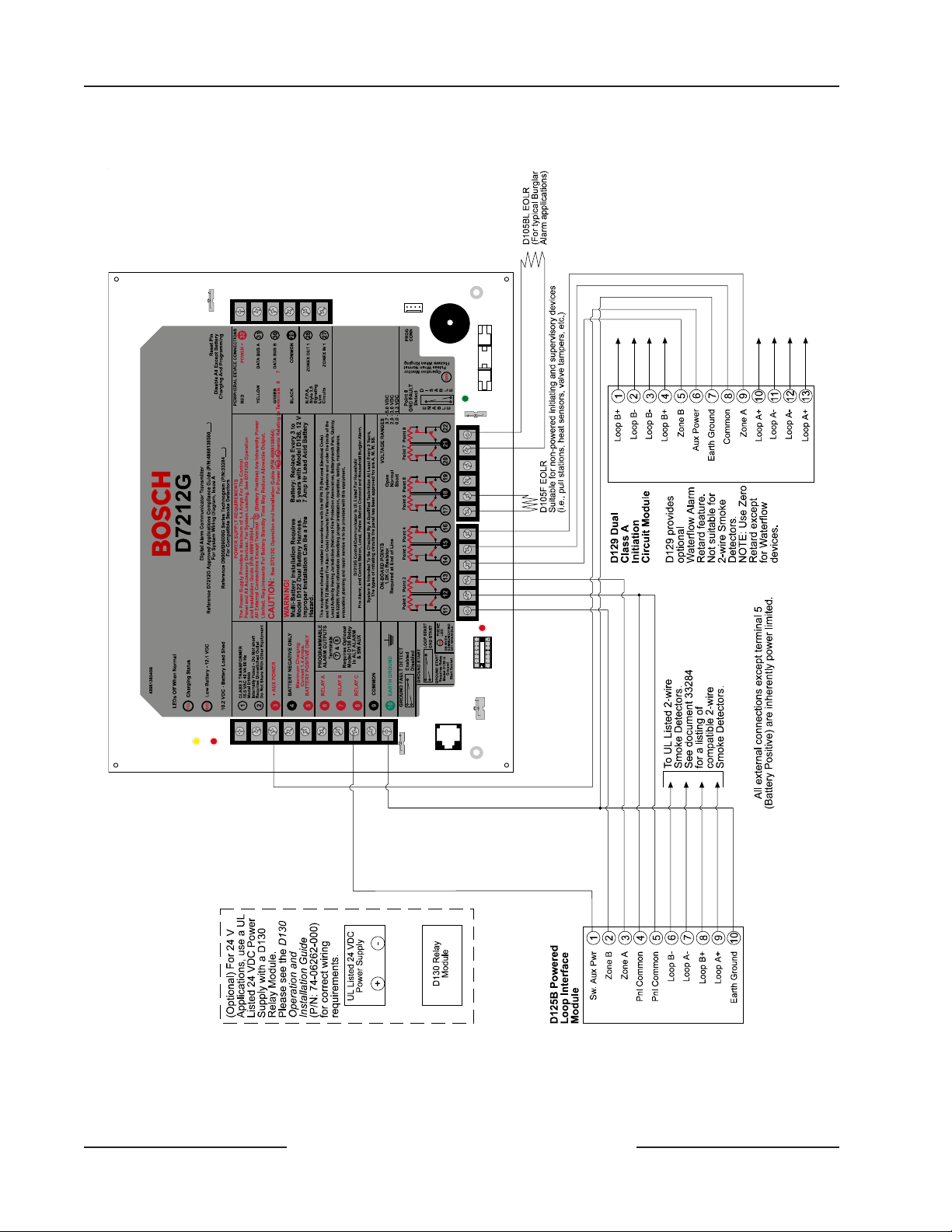
Two-wiresmokedetectorsonlyconnecttothepanelthroughtheD125BPoweredLoopInterfacesothatanearthgroundwill
notcauseanalarm.Two-wiredetectorsmustbeevaluatedforelectricalcompatibility,andmustbeULListedforusewiththe
panel.Seethe9000/9000GSeriesTechnogram:SmokeDetectorCompatibility(P/N:33284),orcontactthedetector
manufacturer.
Otherinitiatingdevices,includingfour-wiresmokedetectorsconnecttothepanelthroughtheD129DualClassAInitiation
CircuitModule, theD125BPoweredLoopInterface,D8127orD9127POPITs,oron-boardpoints.Whenusing4-wire
smokedetectors,installasuitablepowersupervisionunitaccordingtothemanufacturer’sinstructions.UsetheD130Relay
Module,D8129OctoRelay,orTerminal8,SwitchedAuxPowertoprovideresetcapability.SeeSection9.0Off-boardRelaysof
theD7212GOperationandInstallationGuide(P/N:4998138544)fordetailsontheinstallationoftheD8129.
Approved Applications Compliance Guide

D7212G Approved Applications Compliance Guide
Page 6 © 2003 Bosch Security Systems
D7212G
4998138560C
For battery calculations,refer to Table 2 on page 15,Section 5.0 Standby Battery Requirements on page 13, and Section6.0
StandbyBatteryCalculationforNFPA72FireAlarmApplications on page16.
Testweekly: BoschSecuritySystemsrecommendsa FireTest beperformedweekly.TheACpowerisautomatically testedasis
thebatteryperUL985.
1.3.4 Enclosures
BoschSecuritySystemsoffersthreeoptionalenclosuresforthecontrol/communicator.
•TheD8103 enclosureissuitableforresidentialfireand/orburglaryinstallationsandcommercialburglary
applications that donot require attack resistanceor approval by Factory Mutual or NYC-MEA.(See Table1 on
page7foracceptableapplications.)
•TheD8108Aisattackresistant.ItisintendedprimarilyforULcommercialburglaralarmandmercantilesafeand
vaultapplicationsrequiringalocalbell.TheD8108Acanbeusedinanyburglarorfirealarmapplicationwhere
theD8109enclosureissuitable.TheD8108A,withsomemodification,canbeusedforbanksafeandvault
applications(seetheD9412/D9112/D7412/D7212Technogram:ULCertificatedBankSafeandVaultApplications
[P/N:73-07302-000]).ULliststheD8108Aforallcommercialfirealarmapplications.TheD8108Aisapprovedby
FactoryMutual,CaliforniaStateFireMarshal,andtheNewYork CityMaterialsandEquipmentAcceptance
System.
•TheD8109RedFireEnclosureisnormallyusedforfirealarmapplications.ULliststheD8109forallcommercial
firealarm applications.The D8109 isapprovedby the CaliforniaStateFire Marshal,NYC-MEA and FM.
Note: The D7212GisnotULListedforCommercialFire(UL864).
Note: AllreferencestoNFPAandrelatedrequirementsarebaseduponcompliancewithNFPA72,NationalFireAlarm
Code.Sinceinstallationspecificationsarenearlyalwaysbaseduponaspecificeditionofastandardwhichhasbeen
legallyadoptedbytheAuthorityHavingJurisdiction(AHJ),consultwiththeappropriateAHJforconfirmation.
Approved Applications Compliance Guide

D7212G Approved Applications Compliance Guide
D7212G
Page 7© 2003 Bosch Security Systems 4998138560C
2.0 System Chart
Household Burglary
Household Fire
Household Fire/ Burglary
Combined
Central Station Burglary
(Grade C)
Police Connected
Burglary
Local Burglary
Minimum Hours of Standby
Battery 424 +
4
mins
alarm
24 +
4
mins
alarm
444
D8103 Enclosure No No
D8108A Enclosure Req. Req.
D8109 Enclosure
Choose one.
D101 lock required for
enclosure. No No
D122 and D122L Dual Battery
Harness Calculate current draw to determine if second
battery is required.
D125B Class B, Style A
Powered Loop Interface Opt. # # Opt. Opt. Opt.
D129 Class A, Style D Initiating
Module ##
D126/D1218 Battery 1+ 1+ 1+ 1+ 1+ 1+
D127 Reversing Relay Opt. No Opt. Opt. Opt. Opt.
D928 Dual Phone Line Module Opt. Opt. Opt. Opt. Opt. Opt.
D161 Telephone Cord Required to connect panel to RJ31X
TelCo. Block
D185 Auxiliary Interface Kit
D192A/D192C/D192G Class B,
Style W Bell Circuit Supervision Opt. Opt. Opt. Opt. Opt. Opt.
Smoke Detector Base 1++ 1++
D268/D269H Independent Zone
Control Optional, only connect to zones 1 to 8.
Indicating Device 1+ 1+ 1+ Opt. ** **
D461 Pull Station Optional, may be required by job specifications
and/or Authority Having Jurisdiction.
D1255/D1260 Command Center 1+ 1+ 1+ 1+ 1+ 1+
D1256 Opt. Opt. Opt. Opt. Opt. Opt.
D1257 Opt. Opt. Opt. Opt. Opt. Opt.
D1640 Transformer Required for all applications.
D8004 Transformer Enclosure Opt. Opt. Opt. Opt. Opt. Opt.
D8122 Derived Channel S.T.U. Optional, contact TelCo. for availability of derived
channel service.
D8125 Class B, Style 3.5
POPEX Module Required for D8127T/U and D9127T/U POPITs.
D8125MUX Required for MUX devices. Refer to section 4.2.
D8127T/U & D9127T/U Class B,
Style A POPIT Modules Opt. Opt. Opt. Opt. Opt. Opt.
D8128D OctoPOPIT Opt. No Opt. Opt. Opt. Opt.
D8129 OctoRelay Optional, for remote annunciation of system
functions.
D8130 Release Module Optional
D8132 Battery Charger See Current Rating Chart and Standby Battery
Requirements to determine if system requires a
D8132 Module for increased battery standby.
D9131A Parallel Printer Interface Optional, use with parallel printer to print events
from panel log locally.
No = Not acceptable for this application. Req. = Required for this application. Opt. = Optional for this application.
# - D125B and D129 required to connect fire alarm initiating devices to zones 1-8. D125B provides two powered loops for connecting listed
2-wire smoke detectors. D129 provides two non-powered Class A initiating circuits.
1+ = One or more required for this application. Consult the appropriate standard.
1++ = At least one detector required. You can substitute other 2-wire detectors listed for use with the D125. You could also use the D262
with the D270 4-wire base and a listed power supervision relay.
** = Listed bell (siren) housing required for burglary alarm bell or siren.
[Empty Cell] = Not used for this application.
Table 1: UL System Chart
System Chart

D7212G Approved Applications Compliance Guide
Page 8 © 2003 Bosch Security Systems
D7212G
4998138560C
System Chart
Notes:

D7212G Approved Applications Compliance Guide
D7212G
Page 9© 2003 Bosch Security Systems 4998138560C
System Wiring Diagrams, Issue A
3.0 System Wiring Diagrams, Issue A
3.1 D7212G Control/Communicator, 1 of 3
Figure1: D7212G System Wiring Diagram, 1 of 3

D7212G Approved Applications Compliance Guide
Page 10 © 2003 Bosch Security Systems
D7212G
4998138560C
System Wiring Diagrams, Issue A
3.2 D7212G Control/Communicator, 2 of 3
Figure2: D7212G System Wiring Diagram, 2 of 3

D7212G Approved Applications Compliance Guide
D7212G
Page 11© 2003 Bosch Security Systems 4998138560C
System Wiring Diagrams, Issue A
3.3 D7212G Control/Communicator, 3 of 3
Figure3: D7212G System Wiring Diagram, 3 of 3

D7212G Approved Applications Compliance Guide
Page 12 © 2003 Bosch Security Systems
D7212G
4998138560C
System Wiring Diagrams, Issue A
Notes:

D7212G Approved Applications Compliance Guide
D7212G
Page 13© 2003 Bosch Security Systems 4998138560C
Current Rating Charts
4.0 Current Rating Charts
4.1 Current Rating Chart for Standby Battery Calculations
ABC
AC Power On
Normal Current (mA) AC Power Off
Minimum Current
(mA)
In Alarm
Maximum Current
(mA)
Model
Number Quantity
Used Each
Unit*Total Each
Unit Total Each
Unit Total
D7212G ______ 200 x 1 = 200 200 x 1 = 200 500 x 1 = 500
D125B ______ 20 x Quant. = ____ 19 x Quant. = ____ 123 x Quant. = ____
D127 ______ 13 x Quant. = ____ 12 x Quant. = ____ 45 x Quant. = ____
D129 ______ 25 x Quant. = ____ 25 x Quant. = ____ 25 x Quant. = ____
D185 ______ 120 x Quant. = ____ 120 x Quant. = ____ 350 x Quant. = ____
D192C ______ 15 x Quant. = ____ 26 x Quant. = ____ 50 x Quant. = ____
D192G ______ 15 x Quant. = ____ 26 x Quant. = ____ 50 x Quant. = ____
D1255 ______ 104 x Quant. = ____ 106 x Quant. = ____ 206 x Quant. = ____
D1256 ______ 104 x Quant. = ____ 106 x Quant. = ____ 206 x Quant. = ____
D1257 ______ 104 x Quant. = ____ 106 x Quant. = ____ 206 x Quant. = ____
D1260 ______ 95 x Quant. = ____ 97 x Quant. = ____ 200 x Quant. = ____
D720 ______ 55 x Quant. = ____ 20 x Quant. = ____ 75 x Quant. = ____
D8125 ______ 48 x Quant. = ____ 48 x Quant. = ____ 48 x Quant. = ____
D8125MUX* ______ = ____ = ____
D8127T/U ______ 3 x Quant. = ____ 3 x Quant. = ____ 4 x Quant. = ____
D8128D ______ 50 x Quant. = ____ 50 x Quant. = ____ 50 x Quant. = ____
D8129 ______ 20 x Quant. = ____ 20 x Quant. = ____ 20 x Quant. + 25 x
# of relays = ____
D8130 ______ 5 x Quant. = ____ 5 x Quant. = ____ 54 x Quant. = ____
D9127T/U ______ 0.5 x Quant. = ____ 0.5 x Quant. = ____ 0.8 x Quant. = ____
D9131A ______ 24 x Quant. = ____ 22 x Quant. = ____ 36 x Quant. = ____
Ratings of other devices in the system which are not shown above:
________ ______ ____ x Quant. = ____ ____ x Quant. = ____ ____ x Quant. = ____
Total A = _____ Total B = _____ Total C = _____
* See Table 3 on page 14 for determining maximum currents for the D8125MUX and its accessories.
Table 2: CurrentRatingChart for Standby BatteryCalculations

D7212G Approved Applications Compliance Guide
Page 14 © 2003 Bosch Security Systems
D7212G
4998138560C
Current Rating Charts
4.2 Current Rating Chart for D8125Mux
FillinthechartinTable3todeterminethemaximumcurrentsfortheD8125MUXanditsaccessories.Transferthetotal
figurestotheprecedingchart.
Note: ThemaximumcurrentdrawforeachMUXBusis75mA.
AC Power Off
Maximum Current (mA) In Alarm
Maximum Current (mA)
Accessory Model Qty.
Used Each Unit Total
System Each Unit Total
System
DS7432 10 x Qty. = 10 x Qty. =
DS7457 0.35 x Qty. = 0.35 x Qty. =
DS7460 1 x Qty. = 1 x Qty. =
DS7465 1 x Qty. = 1 x Qty. =
Ratings* of other devices on the MUX Buses which arenot shown above:
x Qty. = x Qty. =
x Qty. = x Qty. =
x Qty. = x Qty. =
x Qty. = x Qty. =
x Qty. = x Qty. =
x Qty. = x Qty. =
x Qty. = x Qty. =
x Qty. = x Qty. =
x Qty. = x Qty. =
x Qty. = x Qty. =
x Qty. = x Qty. =
x Qty. = x Qty. =
x Qty. = x Qty. =
x Qty. = x Qty. =
Column A
Total = Column B
Total =
* Refer to the device’s Installation Guide for current draw values.
Table 3: CurrentRatingChart for D8125MUX

D7212G Approved Applications Compliance Guide
D7212G
Page 15© 2003 Bosch Security Systems 4998138560C
Standby Battery Requirements
5.0 Standby Battery Requirements
5.1 Household Burglary and Commercial Burglary
Four hours of standby battery capacity required.
5.2 Bank Safe and Vault
Standbybatterycapacityof72 hoursisrequired(UL365).AuxPowercurrentforalldevices,includingcontrolcenters,must
belimitedto300mAorlesstomeetthisrequirement.
5.3 Household Fire Warning Equipment
Standbybatterycapacityof24hoursplus4minutesofalarmoperationisrequired.SeetheAmpere-HourCalculation
Formula in Section 6.2 Household Fire Warning Equipment on page 16.

© 2003 Bosch Security Systems 4998138560C 05/03
130 Perinton Parkway, Fairport, NY 14450-9199 USA Approved Applications D7212G
Customer Service: (800) 538-5807; Technical Support (888) 886-6189 Compliance Guide Page 16 of 16
6.0 Standby Battery Calculation for NFPA 72 Fire Alarm Applications
6.1 Current Chart First
See Section 4.1 Current Rating Chart for Standby Battery Calculations on page 13 for totals B and C used in the formulas
below.Whenconnectingtwobatteries,useeithertheD122DualBatteryWiringHarnessortheD8132BatteryCharger
Module.
6.2 Household Fire Warning Equipment
TheHouseholdFireWarning EquipmentStandardrequires24hoursof standbyplus4 minutes of alarmoperation atthe
endofthe24hourperiod.Batteryamperehour(Ah)calculationsmustbeusedtoverifycompliance.Thefollowingformula
includesthecalculationfor4minutesofalarmoperationattheendofthe24hourperiod,aswellasa10%contingency
factorwhichallowsfordepletionofbatterycapacitywithage.
HouseholdFireAmpere-HourCalculationFormula
Total B Hours Total C Hours Contingency TotalAh
( ______ x 24 ) + ( ______ x .067 ) + 10% = ______
TotalAhrequirementsmustnotexceedAhcapacityofbatteries:
TwoD126Batteries =14Ah;oneD1218battery=17.2or18Ah
Other manuals for D7212G
1
Table of contents
Other Bosch Cell Phone manuals

Bosch
Bosch DS7060 User manual

Bosch
Bosch B465 User manual

Bosch
Bosch DS7240-UK User manual

Bosch
Bosch CONETTIX B444-A2 User manual

Bosch
Bosch GSM 908 User manual

Bosch
Bosch WORLD 718 User manual

Bosch
Bosch B442 User manual

Bosch
Bosch GSM-Com 608 User manual

Bosch
Bosch D9068 Quick start guide

Bosch
Bosch B465 User manual

Bosch
Bosch Doro Secure 680 User manual

Bosch
Bosch GSM 1900 User manual

Bosch
Bosch GSM 509 User manual

Bosch
Bosch SAFECOM SC3100 Quick start guide

Bosch
Bosch ITS-DX4020-G User manual

Bosch
Bosch B465 User manual

Bosch
Bosch QSM 1800 User manual

Bosch
Bosch GSM 909 DUAL S User manual

Bosch
Bosch GMS 509 DUAL User manual

Bosch
Bosch MM588 User manual