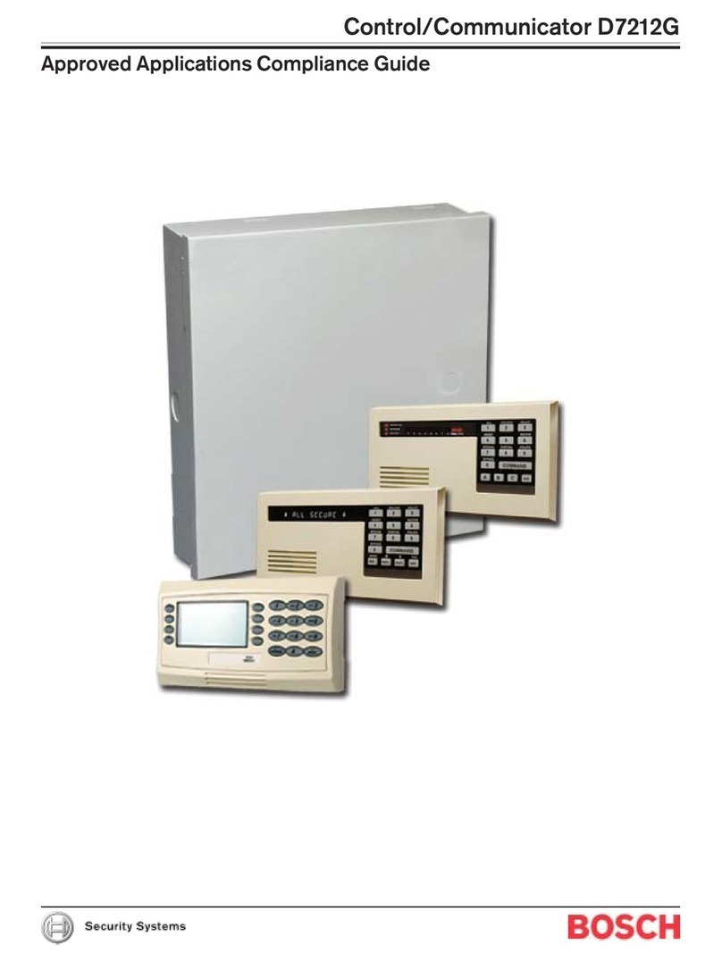
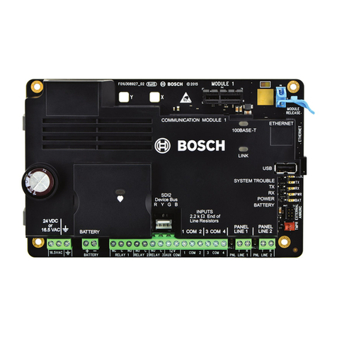
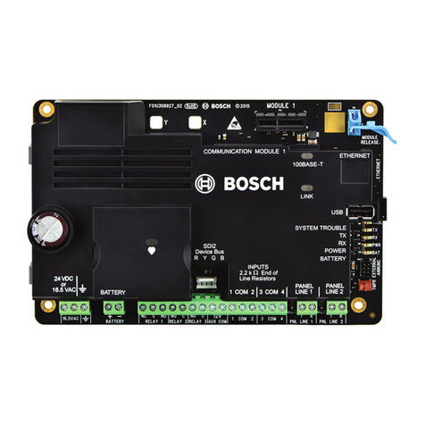
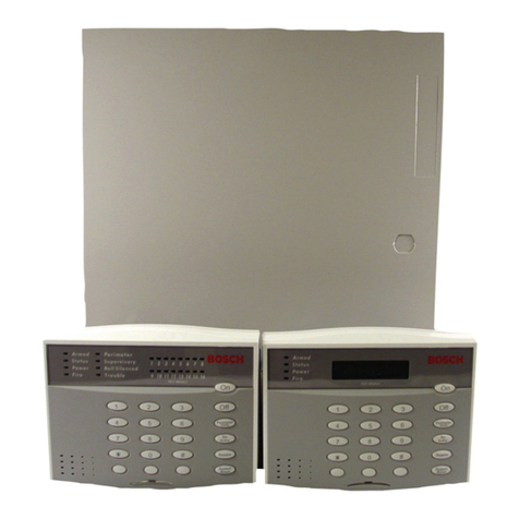
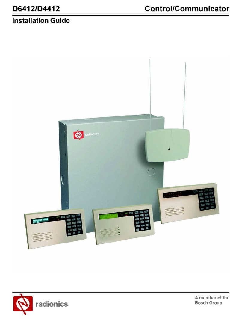
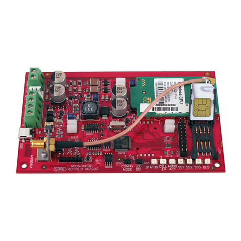
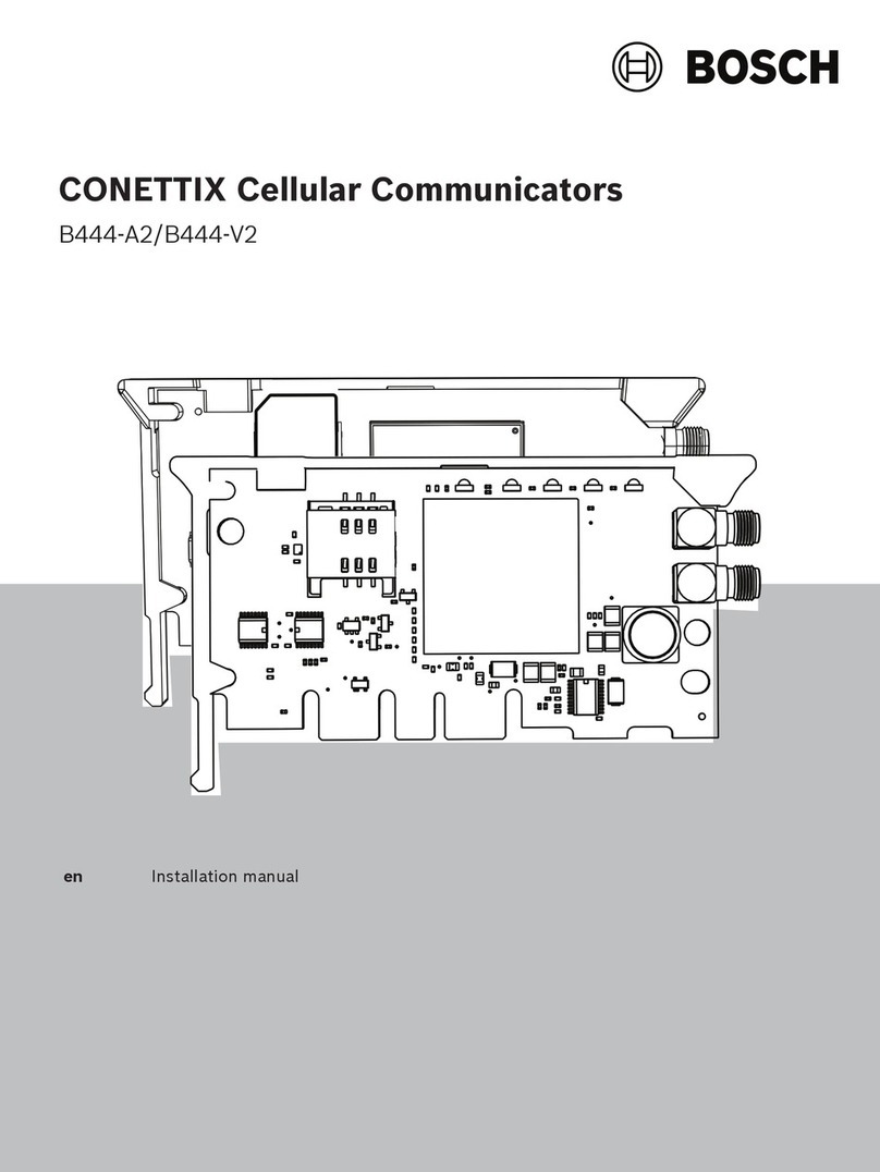
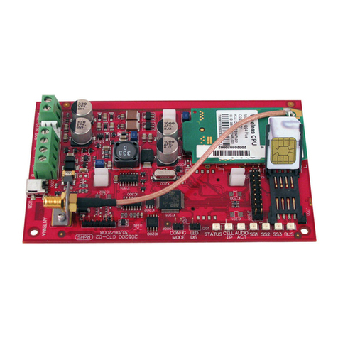
Bosch D9068 Quick start guide

EN
Operation and
Installation Guide
Fire Communicator
D9068

D9068 |Operation and Installation Guide |
2
Bosch Security Systems, Inc. | 3/13 | F01U071094-07
Trademark
Molex is a registered trademark of
Molex Incorporated.
Notices
FCC Compliance Notice
This equipment was tested and complies
with the limits for a Class A digital
device, pursuant to Part 15 of the
Federal Communications Commission (FCC)
Rules. These limits are designed to
provide reasonable protection against
harmful interference in a commercial
installation. This equipment generates,
uses, and can radiate radio frequency
energy. When this equipment is not
installed and used according to the
instructions, it might cause harmful
interference to radio communications.
There is no guarantee that interference
will not occur in a particular
installation.
If this equipment causes harmful
interference to radio or television
reception that can be determined by
turning the equipment off and on,
correct the interference by:
Reorienting or relocating the
receiving antenna.
Increasing the separation between
the equipment and the receiver.
Connecting the equipment to an
outlet on a circuit different from
the circuit to which the receiver is
connected.
Consulting the dealer or an
experienced radio or TV technician
for help.
FCC Telephone Connection to Users
This control complies with Part 68 of
the FCC rules.
The inside of the enclosure has a label
containing the ringer equivalence
number (REN) for this equipment. When
requested, you must provide this
information to your local telephone
company.
The REN helps to determine the quantity
of devices that can be connected to
your telephone line and still have all
of those devices ring when your
telephone number is called. In most
areas, the sum of the RENs of all
devices connected to one line should
not exceed five (5.0). To verify the
number of devices you can connect to
your line, contact your local telephone
company to determine the maximum REN
for your local calling area.
FCC registration number = ESVMUL-46514-
AL-E.
Ringer equivalence = 0.0B.
Do not use this equipment on coin
service provided by the telephone
company or connected to party lines.
If you experience trouble with this
equipment, contact the manufacturer for
information on obtaining service or
repairs.
If this equipment harms the telephone
network, the telephone company might
temporarily discontinue your service.
When possible, the telephone company
notifies you in advance. If advanced
notice is not practical, you are
notified as soon as possible.
You are informed of your right to file
a complaint with the FCC. The telephone
company can make changes in its
facilities, equipment, operations, or
procedures affecting the proper
functioning of your equipment. If they
do, you are notified in advance so that
you can maintain uninterrupted
telephone service.
The telephone company might ask you to
disconnect this equipment from the
network until the problem is corrected,
or until you are sure the equipment is
not malfunctioning.
The manufacturer, not the
user, must make the repairs to
this equipment.
Operating this equipment can also be
affected if events such as accidents or
acts of God interrupt telephone
service.
Industry Canada Notice
The Industry Canada label identifies
certified equipment. This certification
means that the equipment meets certain
telecommunications network protective,
operational, and safety requirements.
Industry Canada does not guarantee that
the equipment operates to the user’s
satisfaction.
Before installing this equipment,
verify that you have permission to
connect it to the facilities of the
local telecommunications company.
Install the equipment using an
acceptable method of connection. Verify
that the customer is aware that
compliance with the above conditions
might not prevent degradation of
service in some situations.
D9068 |Operation and Installation Guide |
.
Bosch Security Systems, Inc. | 3/13 | F01U071094-07
3
An authorized Canadian maintenance
facility, designated by the supplier,
should make the repairs to the
certified equipment. If you make
repairs or modifications to this
equipment, and if the equipment
malfunctions, the telecommunications
company might ask you to disconnect the
equipment.
For your own protection,
ensure that the electrical
ground connections of the
power utility, telephone
lines, and internal metallic
water pipe system, if present,
are connected together.
Do not attempt to make such
connections. Contact the
appropriate electric inspection
authority or electrician.
Installation Guidelines for UL
Systems
Failure to install and program
the D9068 according to the
requirements in this section
voids the listing mark of
Underwriters Laboratories,
Inc. (UL).
Test according to NFPA 72
Chapter 10.4.1.2 (2002) after
any modifications, repairs,
upgrades, or adjustments to
the system.
D9068 UL Requirements
D9068 is UL Listed for Commercial
Digital Alarm Communicator
applications (Type service: remote
station and central station), UL
Standard UL864.
Install the digital alarm
communicator transmitter (DACT)
according to NFPA 72 for Commercial
Fire installations.
Mount the D9068 indoors and within
the protected area.
Ground according to Article 250 of
the NEC (NFPA 70).
Use the supplied screw and clamp
terminal to connect the ground wire
provided with the enclosure. Refer
to Figure 5 on page 12.
Use, enable, and supervise both
telephone lines.
Program a primary and an alternative
telephone number. The numbers must
be different.
Input points might be unsupervised
if the D9068 is mounted within 20 ft
(6 m) of the fire alarm control
panel (FACP) with wiring in a
conduit.
If mounting the D9068 more than 20
ft (6 m) from the FACP, configure
all input points for supervisory
operation.
Use conduit for all
installations.
FACPs using open collector outputs must
be compatibility-listed for use with
the D9068.
Notice to users, installers,
authorities having jurisdiction (AHJ),
and other involved parties:
This product incorporates field-
programmable software. In order for the
product to comply with the requirements
in the Standard for Control Units and
Accessories for Fire Alarm Systems,
UL864, certain programming features or
options must be limited to specific
values or not used at all as indicated
in Table 1.

D9068 |Operation and Installation Guide | Contents
4
Bosch Security Systems, Inc. | 3/13 | F01U071094-07
Table 1: Programming Features
Program Feature or
Option
Permitted in
UL864? (Yes/No)
Possible Settings
Settings Permitted in
UL864
Auto Test
Frequency
Yes
1) 4 h
2) 12 h
3) 24 h
4) 7 days
5) 28 days
6) Disabled
1) 4 h
2) 12 h
3) 24 h
Program Relay
Yes
1) Release on Trouble
2) Activate on Ground
Start
1) Release on Trouble
AC Fail Delay
Yes
1) Wait for DC
2) Wait Delay Time
0-24 h
2) Wait Delay Time 1-3 h
Phone Line Monitor
for Each Line
Yes
0) No
1) Yes
1) Yes
Response Time
Yes
1) Fast (0.5 sec)
2) Programmed
1) Fast (0.5 sec)
2) 1-9 sec

D9068 |Operation and Installation Guide | Contents
.
Bosch Security Systems, Inc. | 3/13 | F01U071094-07
5
Contents
1.0 Overview........................ 7
1.1 System Overview................. 7
1.2 Features and Specifications..... 7
1.2.1 Power........................... 7
1.2.2 System Supervision.............. 7
1.2.3 Inputs.......................... 7
1.2.4 Input Configuration............. 8
1.2.5 Trouble Output.................. 8
1.2.6 User Interface.................. 8
1.2.7 Communication................... 8
1.2.8 History Buffer.................. 9
1.2.9 General Specifications.......... 9
1.2.10 Parts List..................... 9
1.2.11 Printed Circuit Board (PCB)
Layout.......................... 9
2.0 Installation................... 11
2.1 Mounting the Enclosure......... 11
2.2 Connecting the D9068........... 13
2.2.1 Input Point Connections........ 13
2.2.2 Trouble Relay Connections...... 16
2.2.3 Analog FACP Connections........ 17
2.2.4 Telephone Connections.......... 17
3.0 System Start Up................ 19
3.1 System Power-up................ 19
3.1.1 Before Power-up................ 19
3.1.2 After Power Up................. 19
3.2 System Quick Start............. 20
4.0 System Operation............... 20
4.1 Communicator Operation......... 20
4.1.1 Phone Line and Phone Number
Selection...................... 20
4.1.2 Telephone Line Supervision..... 21
4.1.3 Wait for Dial Tone............. 21
4.1.4 Call Routing................... 21
4.1.5 Call Attempts.................. 22
4.1.6 Communication Fault............ 22
4.1.7 Programming Fault.............. 22
4.1.8 Data Lost and Limited Reports.. 22
4.1.9 Communications Tests........... 23
4.2 Input Point Operation.......... 25
4.3 Trouble Relay Operation........ 27
4.4 Keypad Operation............... 27
4.4.1 D7033/FMR-DACT-KEYPAD Keypad
Programmer..................... 27
4.4.2 Scrolling Menus................ 29
4.4.3 Selecting Menu Items........... 30
4.4.4 History........................ 30
4.5 Reset.......................... 32
5.0 Programming.................... 32
5.1 Using the Keypad............... 32
5.2 Programming Key Sequences...... 33
5.3 Program Menu Tree ............. 34
5.4 Programming the D9068 ......... 37
5.4.1 PROG TIME ..................... 37
5.4.2 PROG TIMERS ................... 38
5.4.3 PROG INPUTS ................... 39
5.4.4 PROG RELAY .................... 41
5.4.5 PROG ACC’NTS .................. 42
5.4.6 PROG FORMATS .................. 45
5.4.7 PROG DEFLTS ................... 48
5.4.8 SERIAL CONECTN ................ 49
5.5 Operating Modes ............... 49
5.5.1 0- PROGRAM .................... 50
5.5.2 1- STATUS ..................... 50
5.5.3 2- HISTORY .................... 50
5.5.4 3- TEST ....................... 50
Appendix A: Troubleshooting ......... 51
A.1 On-Board LEDs ................. 51
A.2 Input Points .................. 52
A.3 Trouble Relay ................. 52
A.4 Manual Test Report Failure .... 53
A.5 Reports in Queue .............. 53
A.6 Error During Comm Test ........ 53
Appendix B: 4/2 Reporting Codes ..... 54
Appendix C: Fire Communicator Report
Summary ....................... 56
Appendix D: Programming Defaults .... 61
Appendix E: Report Routing .......... 63
Appendix F: D8024/D10024/D10024A Analog
FACP Operation ................ 64
F.1 Limitations ................... 64
F.1.1 FACP Limitations .............. 64
F.1.2 Restorals ..................... 64
F.2 Setup ......................... 64
F.2.1 D9068 to FACP Power Connections 64
F.2.2 FACP Relay Connections to D9068
(Optional) .................... 66
F.3 Programming ................... 67
F.3.1 FACP Programming .............. 67
F.3.2 D9068 Programming ............. 67
F.4 Reporting Information ......... 67
F.4.1 General Report Information .... 67
F.4.2 Peripheral Events ............. 68
F.4.3 Other Non-Point Events ........ 68
F.4.4 Event Text .................... 68
F.4.5 Sample Reports ................ 69
F.4.6 Analog FACP Event Code to D9068
Report Mapping ................ 70
F.4.7 Reported Event to FACP Cause
Mapping ....................... 72
Figures
Figure 1: D9068 PCB Layout .......... 10
Figure 2: Wire Knockout Locations ... 11
Figure 3: Mounting D9068 Case to Wall 11

D9068 |Operation and Installation Guide | Contents
6
Bosch Security Systems, Inc. | 3/13 | F01U071094-07
Figure 4: Light Pipe................. 11
Figure 5: Mounting the D9068 Board... 12
Figure 6: Conduit Connections........ 12
Figure 7: Molex Connector Descriptions
............................ 13
Figure 8: Open Collector Input Point
Wiring (Supervised)......... 14
Figure 9: Open Collector Output Point
Wiring (Non-supervised)..... 14
Figure 10: Dry Contact Input Point
Wiring (Supervised)......... 15
Figure 11: Dry Contact Input Point
Wiring (Non-supervised)..... 15
Figure 12: Typical Trouble Relay
Connections (Supervised).... 16
Figure 13: Typical Trouble Relay
Connections (Non-supervised) 16
Figure 14: D9068 to Analog FACP
Connections................. 17
Figure 15: RJ31X Wiring.............. 18
Figure 16: Connecting a Keypad to the
D9068....................... 19
Figure 17: System Fault/Fault on Open
Connections................. 27
Figure 18: D7033/FMR-DACT-KEYPAD Keypad
Programmer.................. 28
Figure 19: Additional Functions of the
[Drill], [Disable], and
[Reset] Keys................ 29
Figure 20: Scrolling Main Menu....... 29
Figure 21: Exclusive Keys............ 30
Figure 22: Shared Keys............... 30
Figure 23: Submenu Items............. 30
Figure 24: Event History Example..... 31
Figure 25: Programming Key Sequence for
System Date................. 32
Figure 26: Programming Key Sequence
Diagram..................... 33
Figure 27: 4/2 Point Report Example.. 46
Figure 28: D9068 to D8024 or
D10024/D10024A Power
Connections................. 66
Tables
Table 1: Programming Features ........ 4
Table 2: Power Specifications ........ 7
Table 3: Input Point Specifications .. 8
Table 4: General Specifications ...... 9
Table 5: Parts List .................. 9
Table 6: Report Routing with Primary
and Alternate Phone Number,
Phone 2 Backup ............. 21
Table 7: Input Point Configuration .. 25
Table 8: Input Point Voltage Levels . 26
Table 9: System Fault (Fault or Open)
Voltage
Levels ..................... 26
Table 10: D7033/FMR-DACT-KEYPAD and
FMR-DACT-KEYPAD Keypad
Function ................... 29
Table 11: Event History Abbreviations 31
Table 12: Sys Trouble LED Indications 52
Table 13: 4/2 Reporting Codes ....... 54
Table 14: Reporting Summaries ....... 57
Table 15: Equipment Fail Conditions . 59
Table 16: Point Related Report Routing
........................... 63
Table 17: Non-Point Related Report
Routing .................... 63
Table 18: D9068 Input to FACP Event
Messages ................... 67
Table 19: Point Event Coding ........ 68
Table 20: Alarm Report Mapping ...... 68
Table 21: Sample Reports ............ 69
Table 22: Analog FACP Event Codes ... 70
Table 23: Analog Reports and Causes . 72

D9068 |Operation and Installation Guide | 1.0 Overview
.
Bosch Security Systems, Inc. | 3/13 | F01U071094-07
7
1.0 Overview
1.1 System Overview
The D9068 Fire Communicator is a
complete communicator for use with
compatible FACPs. Alarms and
communications to the D9068 are
accomplished using dry contacts or open
collector outputs.
The D9068 also includes:
12 VDC or 24 VDC operation
Multiple data protocols (Modem IIIa2,
Contact ID, SIA, and 4/2)
100-event history buffer
Five programmable discrete wire
inputs (Class B)
Dual telephone line interface
Option bus interface for built-in
programming using the D7033/FMR-
DACT-KEYPAD Keypad Programmer
Form C relay output for trouble
LEDs for heartbeat, system trouble,
and telephone line trouble (one per
line)
Serial port for connection to other
FACPs (such as the Bosch D8024 and
D10024/D10024A Analog FACPs)
Real-time clock
1.2 Features and Specifications
1.2.1 Power
Do not share power from the
FACP with the D9068 and other
peripheral devices.
Table 2: Power Specifications
Power Specifications
D9068 Value
Input voltage range
(use power-limited
source)
10.2 VDC to 28 VDC
for filtered DC
12 VRMS to 28 VRMS
for unfiltered DC
Standby current
150 mA Maximum
Alarm current
190 mA maximum
Although the D9068 can withstand short
power losses up to 5 min, connect it to
an unswitched, uninterrupted power
source.
If the D9068 loses power for more than
5 min:
The history buffer might clear and
all stored events are lost.
The output (report) buffer might
clear and all pending reports are
lost.
Alarms initiated before the power
loss might reset. If the alarm
conditions persist when power is
restored, new alarms can be
generated.
System time might reset to its
default setting.
If a power loss occurs,
programmed settings such as
input point configuration,
telephone numbers, and account
number remain intact.
1.2.2 System Supervision
Watchdog: The D9068 is supervised with
a hardware watchdog circuit. Failure of
the control program causes a hardware
reset within 2 sec. The trouble relay
is released for the duration of the
reset. Generally, this relay is held
energized.
Self Testing: Occasionally, the dialer
(DACT), EEPROM memory, input points,
and telephone lines are automatically
tested. The EEPROM checksum is verified
every 10 min. If the EEPROM checksum
fails, a trouble condition is
annunciated locally and a Trouble
Report is sent.
1.2.3 Inputs
The D9068 supports five inputs that can
be activated by dry contact relays or
open collector outputs. The open
collector outputs from the fire panel
must be below 1.3 VDC in alarm and must
sink 5 mA minimum. Refer to Table 3for
input point specifications.

D9068 |Operation and Installation Guide | 1.0 Overview
8
Bosch Security Systems, Inc. | 3/13 | F01U071094-07
Table 3: Input Point Specifications
Number of Points
5
Circuit Type
Class B (Style 4)
EOL Resistor
2.21 kΩ; UL Listed;
Bosch (P/N: 25899)
Alarm Operation
Short to ground or
voltage less than
1.3 VDC
Minimum Alarm
Voltage
Less than 1.3 VDC
Maximum Line
Resistance
50 Ω
Response Time
500 ms
1.2.4 Input Configuration
Initiating circuits or points can be
configured for seven types of
conditions: Fire Alarm, Waterflow
Alarm, Supervisory, Monitor Alarm,
System Fault, AC Failure, and Low
Battery. Refer to Section 4.2 Input
Point Operation on page 25 and 1:
CONFIGURE in Section 5.4.3 PROG INPUTS
on page 39 for more information.
1.2.5 Trouble Output
The D9068 has one Form C relay rated 1
A at 30 VDC. The Form C relay, which is
normally held activated, deactivates
for any trouble condition the D9068
detects. Refer to Section 4.3 Trouble
Relay Operation on page 27 for more
information.
When the D9068 is deployed on a ground
start network, the Form C relay can be
programmed alternatively to serve as a
ground start relay.
Ground start is not UL
compliant.
1.2.6 User Interface
A D7033/FMR-DACT-KEYPAD Keypad
Programmer connects to a five-pin
connector. It is used to program and
troubleshoot the D9068. The D7033/FMR-
DACT-KEYPAD can be set to any address
from 1 to 15.
Use the D7033/FMR-DACT-KEYPAD
only to program the D9068.
Connect this keypad to the
D9068 only temporarily for
programming.
1.2.7 Communication
Formats
The D9068 supports four protocols:
Modem IIIa2, Contact ID, SIA, and 4/2.
Report Routing
Six different report groups can be
routed to one of the following phone
settings:
PHONE 1 ONLY: The report is sent to
Phone 1 only.
PHONE 2 ONLY: The report is sent to
Phone 2 only.
PHON 1 & 2: The report is sent to
Phones 1 and 2.
PHN 2 BACKUP: The report is sent to
Phone 1, and then to Phone 2 if
Phone 1 fails.
These reporting groups consist of non-
supervisory alarms (NONSUP ALRM),
supervisory alarms (SUPVSY ALRM), alarm
restorals and resets (ALM RSTR, RST),
supervisory restorals (SUPVSY RSTR),
tests (TESTS), and troubles and trouble
restorals (TBL, TBLRSTR).
Refer to Section 4.1.4 Call Routing on
page 21, 4: RPT STEERING on page 44,
and Appendix E: Report Routing on page 63
for more information about report
steering.
Reset Report
The Reset Report is issued when the
D9068 is reset from any off normal
condition.
Telephone Line Selection
The D9068 follows a predetermined
sequence to choose between the two
telephone lines. It also implements the
new NFPA requirements for alternating
telephone lines during test reporting.
The D9068 maintains a variable that
selects either Phone Line 1 or Phone
Line 2 for Auto Test Reports. After
each successful Test Report, the
variable switches to select the other
telephone line. Users can select the
telephone line for Manual Test Reports.
Communication Failed Indication
The D9068 indicates a communication
failure after ten attempts to
communicate are completed without
success. This causes the trouble output
to activate and attempt to report the
fault.

D9068 |Operation and Installation Guide | 1.0 Overview
.
Bosch Security Systems, Inc. | 3/13 | F01U071094-07
9
1.2.8 History Buffer
The D9068 has a history buffer that
retains up to 100 events. Each event is
tagged with the date and time of
occurrence. This buffer can be viewed
when a D7033/FMR-DACT-KEYPAD is
attached to the D9068. When the buffer
is full, old events are discarded to
make room for new events. A watchdog
reset is entered in the buffer and does
not reset the buffer.
The history buffer can clear
when the system loses power
for more than 5 min.
1.2.9 General Specifications
Table 4: General Specifications
Storage/Operating
Temperature
+32°F to +120°F
(0°C to +49°C)
Lightning Protection
Metal oxide
varistors (MOVs)
and spark gaps
provide protection
from lightning
surges and static
discharges for
inputs and
telephone
interface.
1.2.10 Parts List
Table 5 on page 9identifies the parts
shipped with the D9068.
Table 5: Parts List
Quantity
Part
1
Enclosure
1
Self-tapping screw
1
Self-tapping screw for cover
1
D9068 PC Board in static bag
4
PC Board Mounting screws
4
PC Board mounting clips
4
Sets cable assemblies
2
Sets telco cable assemblies
RJ31X
1
Ground wire
5
2.21 kΩend-of-line (EOL) resistors; UL
Listed; Bosch (P/N: 25899)
1
Light pipe
Refer to Figure 5 on page 12
for the ground wire
connections. Refer to Figure 6
on page 12 for the cable
assembly connections.
1.2.11 Printed Circuit Board (PCB)
Layout
Figure 1 shows the layout of the D9068
PCB.

D9068 |Operation and Installation Guide | 1.0 Overview
10
Bosch Security Systems, Inc. | 3/13 | F01U071094-07
Figure 1: D9068 PCB Layout
LINE 1
LINE 2
+ + - - A B 1 2 3 4 5 NC C NO
SYS TROUBLE
HEARTBEAT
KEYPAD
12 11 10 8
1
3
2
4
5
1*
7
6
9
1
1 - Mounting hole (4)
2 - Phone line 1
3 - Phone line 1 LED
4 - Phone line 2
5 - Phone line 2 LED
6 - System trouble LED
7 - Heartbeat LED
8 - Common trouble relay connector
pins
9 - Keypad Molex connector pins
10 - Input Molex connector pins
11 - Serial connector pins
12 - Power Molex connector pins
* Attach the ground wire at the mounting hole on the lower right corner.

D9068 |Operation and Installation Guide | 2.0 Installation
.
Bosch Security Systems, Inc. | 3/13 | F01U071094-07
11
2.0 Installation
You can install the D9068 up
to 500 ft
(152 m) from the FACP when
using a minimum of 18 AWG
wire.
Mount the D9068 indoors in a
dry location.
2.1 Mounting the Enclosure
The D9068 and its enclosure are shipped
together. Install the D9068 inside the
enclosure using the supplied mounting
hardware.
1. Remove the desired wire knockouts on
the enclosure. Refer to Figure 2.
Figure 2: Wire Knockout Locations
5
64
12
4
7
3
1 - Left exterior
2 - Right exterior
3 - Tamper switch holes (not used)
4 - Wire knockouts (5)
5 - Machine screw
6 - Self-tapping screw
7 - Front
2. Using the D9068 case as a template,
mark the mounting hole locations on
the desired wall.
3. Hang the case on the wall using the
appropriate installer-supplied
mounting screws (refer to Figure 3).
Figure 3: Mounting D9068 Case to Wall
11
2
3
4
3
1 - Position the enclosure with this
end up
2 - Enclosure mounting holes (2)
3 - Enclosure lances (4)
4 - D9068 mounting holes (3)
4. Slide the light pipe over the end of
the PCB (refer to Figure 4),
aligning it with the LEDs.
Figure 4: Light Pipe
1 - D9068 PCB
2 - Light pipe
5. Mount the D9068 in the enclosure
using the supplied mounting screws
and mounting clips. Then attach the
ground wire from the FACP earth
ground to the earth ground terminal
on the DACT enclosure (refer to
Figure 5 on page 12).

D9068 |Operation and Installation Guide | 2.0 Installation
12
Bosch Security Systems, Inc. | 3/13 | F01U071094-07
Figure 5: Mounting the D9068 Board
LINE 1
LINE 2
+ + - - A B KEYPAD
1 2 3 4 5 NC C NO
SYS TROUBLE
HEARTBEAT
2
3
4
7
8
56
9
10
1
1 - D9068 installed in enclosure
2 - Support post assembly
3 - Light pipe
4 - D9068 PCB
5 - Lance
6 - Enclosure
7 - Mounting clip
8 - Screw
9 - Ground wire to earth ground
terminal connection on the FACP
(this connection is under the
metal edge of the D9068)
10 - Metal edge
6. Connect the D9068 and FACP using conduit (refer to Figure 6).
Figure 6: Conduit Connections
1 - FACP
2 - Conduit
3 - Use no more than 500 ft (152 m) of
wire to connect the FACP to the
D9068
4 - D9068

D9068 |Operation and Installation Guide | 2.0 Installation
.
Bosch Security Systems, Inc. | 3/13 | F01U071094-07
13
The FACPs using open collector outputs must be compatibility listed. When
installing the D9068 more than 20 ft (6 m) from the FACP, configure the
inputs for supervised operation. The D9068 can be installed up to 500 ft
(152 m) from the FACP.
2.2 Connecting the D9068
2.2.1 Input Point Connections
Remove all power before making or breaking any connections to the D9068.
Failure to do so can cause personal injury and/or damage to the
equipment.
When making connections to the D9068, refer to Figure 7 through Figure 13 on this
page through page 16.
Figure 7: Molex Connector Descriptions
+ + - - A B 1 2 3 4 5 NC C NO
KEYPAD
1
3
2 4
14
5
678
9
10
11
10
12
13
15
16
17
18
19
1 - Red (Power +)
2 - Black (Power -)
3 - TXIA
4 - RXIB
5 - White/Brown (Input Point 1)
6 - White/Red (Input Point 2)
7 - White/Orange (Input Point 3)
8 - White/Yellow (Input Point 4)
9 - White/Blue (Input Point 5)
10 - Black
11 - Red
12 - Green
13 - Yellow
14 - Terminal not used
15 - Common trouble relay*
16 - Keypad programmer
17 - Inputs (refer to Table 3on page 8
for input specifications)
18 - Serial connection pins
19 - Power (refer to Table 2on page 7
for specifications)
* Connect the relay to an input on the FACP for trouble annunciation.
The contact position shows an off-normal condition. Under normal
operation, the trouble relay is energized. C and NO are connected.

D9068 |Operation and Installation Guide | 2.0 Installation
14
Bosch Security Systems, Inc. | 3/13 | F01U071094-07
Figure 8: Open Collector Input Point Wiring (Supervised)
+A B 1 3 4 5 NC C NO
-
+-2KEYPAD
Earth Ground
Panel Ground
Open Collector Output
Power (+)
6
7
5
3
2
1
4
8
1 - D9068
2 - Power + (red)
3 - Panel ground (black)
4 - Point 2 (white and red)
5 - Keypad terminals
6- Earth ground (green)
7 - EOL resistor 2.21 k
, UL Listed,
Bosch (P/N: 25899)
8 - FACP (refer to Section 1.2.1 Power
on page 7.)
The open collector output must current sink a minimum of 5 mA. The alarm
voltage must not exceed 1.3 VDC when activated.
Figure 9: Open Collector Output Point Wiring (Non-supervised)
7
1
+A B 1 3 4 5 NC C NO
-
Earth Ground
Panel Ground
Open Collector Output
Power (+)
+-2KEYPAD
6
5
3
24
1 - D9068
2 - Power + (red)
3 - Panel ground (black)
4 - Point 2 (white and red)
5- Keypad terminals
6 - Earth ground
7 - FACP (refer to Section 1.2.1 Power
on page 6.)
For UL installations, non-supervised operation requires installation
within 20 ft (6 m) inside the conduit.
Open collector output must current sink a minimum of 5 mA. The alarm
voltage must not exceed 1.3 VDC when activated.

D9068 |Operation and Installation Guide | 2.0 Installation
.
Bosch Security Systems, Inc. | 3/13 | F01U071094-07
15
Figure 10: Dry Contact Input Point Wiring (Supervised)
+ A B 3 4 5 NC C NO
2
-1
Panel Ground
NO
C
NC
Dry
Contact
Relay
-
Power (+)
+
Earth Ground
KEYPAD
1
6
5
3
2 4
8
7
1 - D9068
2 - Power + (red)
3 - Power –(black)
4 - Point 1 (white and brown)
5- Keypad terminals
6 - Earth ground (green)
7 - EOL resistor: 2.21 k
, UL Listed,
Bosch (P/N: 25899)
8 -FACP
Figure 11: Dry Contact Input Point Wiring (Non-supervised)
+ A B 3 4 5 NC C NO
2
-1
Panel Ground
NO
C
NC
Dry
Contact
Relay
-
Power (+)
+
Earth Ground
KEYPAD
1
6
5
3
2 4
7
1 - D9068
2 - Power + (red)
3 - Power –(black)
4 - Point 1 (white and brown)
5- Keypad terminals
6 - Earth ground (green)
7 - FACP
For UL installations, non-supervised operation requires installation
within 20 ft (6 m) inside the conduit.

D9068 |Operation and Installation Guide | 2.0 Installation
16
Bosch Security Systems, Inc. | 3/13 | F01U071094-07
2.2.2 Trouble Relay Connections
Refer to Figure 12 when making connections to the D9068 Trouble Relay terminals.
Figure 12: Typical Trouble Relay Connections (Supervised)
2
5
+ + -A B 3 4 5 NO
2
-1NC C
{
Zone
Input
Earth
Ground
KEYPAD
1
34
1 - D9068
2 - Keypad terminals
3 - EOL resistor (Refer to the FACP
Installation Instructions for UL
approved EOL resistor specifications.
4 - Earth ground (green)
5 - FACP
The contact position shows the energized condition (normal standby).
Figure 13: Typical Trouble Relay Connections (Non-supervised)
2
1
4
+ + -A B 3 4 5 NO
2
-1NC C
{
Zone
Input
Earth
Ground
KEYPAD
3
1 - D9068
2 - Keypad terminals
3 - Earth ground (green)
4 - FACP
For UL installations, non-supervised operation requires installation
within 20 ft (6 m) inside the conduit.
The contact position shows an energized condition, normal standby.

D9068 |Operation and Installation Guide | 2.0 Installation
.
Bosch Security Systems, Inc. | 3/13 | F01U071094-07
17
2.2.3 Analog FACP Connections
Use the D9068 with the Bosch D8024 and D10024/D10024A Analog FACPs to send reports
to a central station. A D9052 RS-232 Bus Module between the FACP and D9068 is
required. The FACP must be assigned a network address of 1. Refer to Appendix F:
D8024/D10024/D10024A Analog FACP Operation on page 64 for the events generated by
the D8024 and D10024/D10024A.
Although the D9068 supervises its connection to the D8024 and D10024/D10024A, the
analog FACPs do not supervise the connection of the D9068. If the RS-232 link
between the D9068 and FACP is broken, the D9068 recognizes the problem but the
FACP does not.
Figure 14: D9068 to Analog FACP Connections
2
1
3
+3 4 5 NC C NO
2
-1
+KEYPAD
RTS
TX
RX
GND
-AB
45
6
7
1 - D9068
2 - Keypad terminals
3 - Request to send (not used)
4 - Serial transmit
5 - Serial receive
6 - Ground
7 - D9052
For UL installations, non-supervised operation requires installation
within 20 ft (6 m) inside the conduit.
The D9052 mounts on the D8024 and D10024/D10024A PCB. Refer to the
installation instructions that accompany the analog FACP and the D9052
RS-232 Bus Module for details.
For installations requiring the FACP to recognize faults on the D9068, connect the
D9068’s relay output to an analog input module such as a D326A or D339A Point
Contact Module. Configure the points on the FACP for Action Fault. Configure the
relay on the D9068 for Release on Trouble.
2.2.4 Telephone Connections
Telephone Cord Installation
Connect the primary phone line to the D9068 Modular Jack Line 1 using a telephone
cord. Connect the secondary phone line to the D9068 Modular Jack Line 2 using
another telephone cord.
For all applications, connect separate primary and secondary phone lines
to the D9068.

D9068 |Operation and Installation Guide | 2.0 Installation
18
Bosch Security Systems, Inc. | 3/13 | F01U071094-07
Location
To prevent jamming of alarm and other
reports, wire and locate the RJ31X jack
so that normal phone use is temporarily
interrupted while the D9068 transmits
data (refer to Figure 15). After
installation, verify that the D9068
seizes the line, acquires the dial tone,
and reports correctly to the receiver.
Figure 15: RJ31X Wiring
1
2
3
6
7
8
4
52
3
4
5
6
1
1 - Full modular phone jack
2 - Ring (telco)
3 - Tip (telco)
4 - RJ31X Module
5 - T1 (house telephone tip)
6 - R1 (house telephone ring)
Use the supplied telco cable
assemblies to connect to an
RJ31X jack. Ensure that the
RJ31X jacks are mounted in a
secure location to prevent
unwanted disconnections or
tampering.
Notification
Do not connect registered equipment to
party lines or coin-operated telephones.
If the local telephone company requests
notification before you connect the
D9068 to the telephone network, tell
them:
Which line you are connecting to the
DACT.
The make, model, and serial number of
the device.
The FCC registration number
(ESVMUL-46514-AL-E) and ringer
equivalence (0.0B).
If the telephone company changes its
communications facilities, equipment,
operations, or procedures that could
affect the performance of the D9068, the
telephone company is obligated to notify
the user in writing.
The D9068 meets the UL1950 requirements.
Connecting the Keypad to the D9068
The LCD Remote Keypad is used
strictly for programming and
debugging purposes.
Use the D7033/FMR-DACT-KEYPAD Keypad
Programmer to operate the D9068
Communicator. Remove the cover from the
D9068 case and connect the Molex
connector from the D7033/FMR-DACT-KEYPAD
to the connector pins located on the
D9068 board.
When programming the D9068 from the
keypad:
1. Set the D7033/FMR-DACT-KEYPAD address
between 1 and 15.
2. Use the wire connector supplied with
the D9068 to connect the keypad to
the D9068 (Figure 16 on page 19).

D9068 |Operation and Installation Guide |
.
Bosch Security Systems, Inc. | 3/13 | F01U071094-07
19
Figure 16: Connecting a Keypad to the
D9068
LINE 1
LINE 2
+ + - - A B 1 2 3 4 5 NC C NO
SYS TROUBLE
HEARTBEAT
KEYPAD
1
2
3
54
6
7
1 - D9068 Fire Communicator
2 - Keypad terminals
3 - Data out (yellow)
4 - Data in (green)
5 - Com (two black wires)
6 - +12 VDC (red)
7 - Keypad terminals
3. Program the D9068 as explained in
Section 5.0 Programming on page 32.
If no keypad activity occurs
for 3 min, the keypad disables.
The keypad’s buzzer sounds and
a SYSTEM FAULT message appears
on the keypad. Disconnect the
keypad from the D9068 by
removing the wire harness plug
from the D9068’s keypad pins.
Then reconnect the wire plug
harness to re-enable the
keypad.
.
During the installation of the
D7033/FMR-DACT-KEYPAD Keypad
Programmer, the system does not
monitor the input points or the
serial connection to an FACP.
3.0 System Start Up
3.1 System Power-up
This section describes the proper
sequence of events when first powering
up the D9068.
3.1.1 Before Power-up
Before applying power to the D9068,
verify:
All wiring connections are made
according to Section 2.2 Connecting
the D9068 on page 13.
All connectors are firmly seated onto
their appropriate headers. Refer to
Section 2.2 Connecting the D9068 on
page 13.
Input power requirements comply with
the power specifications in Table 1
on page 4. The power supplied to the
D9068 from the FACP is not shorted
and meets the necessary power
requirements for the D9068.
All telephone line connections are
made according to Figure 13 on page
16.
Both RJ31X male connectors are firmly
seated in the RJ31X female connectors
located on the D9068 board.
All input points are properly
terminated with the supplied 2.2 k
EOL resistors for supervised
operation.
The trouble relay connections are
made according to Figure 11 on page
15 and Figure 12 on page 16.
3.1.2 After Power Up
After power is applied to the D9068,
verify that the following conditions
occur:
All LEDs light briefly and the
trouble relay toggles.
The System Trouble LED lights.
The Heartbeat LED flashes to indicate
that the D9068 is functional.

D9068 |Operation and Installation Guide | 4.0 System Operation
20
Bosch Security Systems, Inc. | 3/13 | F01U071094-07
3.2 System Quick Start
The D9068 starts in a trouble condition
until the installer completes the
following steps:
1. Connect the D7033/FMR-DACT-KEYPAD
Keypad Programmer. Refer to
Connecting the Keypad to the D9068 in
Section 2.2.4 Telephone Connections
on page 17.
2. Program the D9068 using the
D7033/FMR-DACT-KEYPAD. Refer to
Section 5.1 Using the Keypad on page
32.
3. Configure the five input points.
Refer to 1: CONFIGURE in Section
5.4.3 PROG INPUTS on page 39.
4. Assign the D9068 account numbers.
Refer to 1: ACCOUNT NUMS in Section
5.4.5 PROG ACC’NTS on page 42.
5. Assign the D9068 telephone numbers.
Refer to 2: PHONE NUMS in Section
5.4.5 PROG ACC’NTS on page 42.
When you complete Steps 1 through 5,
refer to Section 5.0 Programming on page
32 to finish the programming sequence.
If the D9068 is correctly
programmed and the input wiring
is properly connected and
supervised, only the Heartbeat
LED flashes. This indicates
normal system operation.
To verify correct
communications, perform a
manual Communications Test.
Refer to 1: TEST COMM in
Section 5.5.4 3- TEST on page
50 for manual communication
testing instructions.
Test the system according to
NFPA 72 Chapter 10.4.1.2 (2002)
after modifications, repairs,
upgrades, or adjustments.
Refer to Appendix A:
Troubleshooting on page 51 for
information on error messages
or messages indicating abnormal
operating conditions.
4.0 System Operation
4.1 Communicator Operation
The D9068 has an integrated communicator
that sends reports to a monitoring
station. The communicator operates
automatically.
When events occur, the communicator
sends corresponding reports to the
monitoring station by priority according
to NFPA requirements. Fire and water-
flow alarms are sent first, followed by
supervisory alarms and trouble reports,
and finally by all other reports.
4.1.1 Phone Line and Phone Number
Selection
To comply with UL and NFPA
standards, program a primary
and an alternate telephone
number. The numbers must be
different.
The D9068 can report to two telephone
numbers with full single, double, and
backup reporting. It communicates in
Modem IIIa², Contact ID, SIA, and
4/2 formats.
To verify the delivery of critical
reports, the D9068 can report over two
phone lines. Reports can be directed to
one or both of the two phone numbers
using the report steering feature in the
D9068 programming. Account Number 1 is
used with Phone Number 1 and Account
Number 2 is used with Phone Number 2.
Except for Test Reports, the
D9068 automatically selects the
telephone line to use.
Report Routing
Reports are routed in two ways:
1. Report routing starts using Phone
Number 1 on Phone Line 1, unless the
line monitor shows Phone Number 1 to
be bad at the start of reporting. If
the report fails on Phone Number 1 on
Phone Line 1, the D9068 automatically
switches and uses Phone Number 2 on
Phone Line 1.
2. If the report still fails on either
phone number on Phone Line 1, the
D9068 tries to send the report on
Phone Line 2 using Phone Number 1. If
this fails, it tries Phone Number 2
on Phone Number 1.
Table of contents
Other Bosch Cell Phone manuals

Bosch
Bosch ITS-DX4020-G User manual

Bosch
Bosch ITS-DX4020-G Operating instructions

Bosch
Bosch MM588 User manual

Bosch
Bosch B465 User manual

Bosch
Bosch B442 User manual

Bosch
Bosch B441 User manual

Bosch
Bosch WORLD 718 User manual

Bosch
Bosch DS7060 User manual

Bosch
Bosch B465 User manual

Bosch
Bosch Conettix ITS-300GSM User manual

Bosch
Bosch B465 User manual

Bosch
Bosch B443 User manual

Bosch
Bosch GSM 908 User manual

Bosch
Bosch B440 User manual

Bosch
Bosch GSM 509 User manual

Bosch
Bosch GSM-Com 608 User manual

Bosch
Bosch SAFECOM SC3100 Quick start guide

Bosch
Bosch D7212G User manual

Bosch
Bosch GMS 509 DUAL User manual

Bosch
Bosch GSM 909 DUAL S User manual