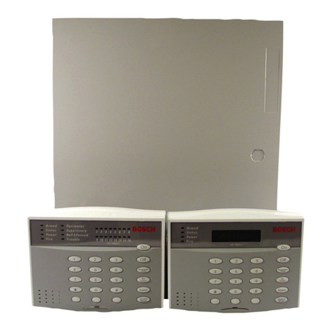
Bosch DS7060 User manual

Reference Guide
for the
DS7060 Control/Communicator
DS7443 KEYPAD DS7445 KEYPADDS7447 KEYPAD
Armed
Status
Power
Fire
On
Off
1 2 3
456
789
0
*#Bypass
Perimeter
No
Entry
Only
System
Reset
321
654
987
#0
*
On
No
Entry
System
Reset
Bypass
Perimeter
Only
Off
Fire
Armed
Status
Power
1
2
3
4
5
6
Armed
Status
Power
Fire
On
Perimeter
Supervisory
Bell Silenced
Trouble
1 2 3 4 5 6 7 8
1 2 3
456
789
0
*#
No
Entry
Reset
Off
Bypass
System
Only
Perimeter
Keypad Quick Reference Guide
Turning On (arming) your System
Normal Arming PIN + [On]
Perimeter Arming, no entry delay PIN + [No Entry] [Perimeter Only]
Perimeter Arming, with entry delay PIN + [Perimeter Only]
Maximum Security Arming PIN + [No Entry] [On]
Force Arming PIN + Arming Sequence + [Bypass]
Zone Bypass PIN + [Bypass] followed by the Zone number
Custom Arm PIN + [#] + [4]
Quick Arm [#] + [On]
Turning Off (disarming) your System
PIN + [Off]
Commands for other System Features
Chime Mode PIN + [#] [7]
Zone Test PIN + [#] [8] [1]
Read Alarm History PIN + [#] [8] [9]
Battery Test PIN + [System Reset]
Communicator Test PIN + [#] [8] [2]
Fire Reset PIN + [System Reset]
Fire Trouble PIN + [Off] to silence, PIN + [System Reset] to clear
Remote Program Dial Out PIN + [#] [8] [3]
Remote Program Answer PIN + [#] [8] [6]
Local Battery/Sounder Test PIN + [#] [8] [5]
Error Display PIN + [#] [8] [7]
Error Display Reset PIN + [System Reset]
Clear Zone Bypass PIN + [Bypass] [*] to clear
Guest Code Enable PIN + [#] [8] [4]
NOTE: Examples are shown in Commercial Mode, but are valid for any mode.

Page 2Copyright 2001 Detection Systems, Inc. DS7060-AUS Reference Guide
1.0 System Overview
The DS7060 Control/Communicator is a fully integrated
hard-wire security and residential fire alarm system. It can
support up to 6 input zones and 15 individual users. Up to
4 keypads may be used to provide user interface with the
system, as well as programming access for the installer.
2.0 Specifications
2.1 Enclosure Housing
The enclosure is manufactured from 22 Ga. (0.65 mm),
cold-rolled steel, and measures 9.25" Wide, by 10.25"
High, by 3" Deep (23.5 cm Wide, by 26 cm High, by 7.6
cm Deep). The door has a knockout for a standard DS
lock (optional). The enclosure has a slot in the back and
also has an optional tamper switch mounting bracket with
a plunger switch.
2.2 Temperature
•Operating temp: +32° to +120°F (0° to +49°C)
•Storage temp: -20° to +150°F (-28° to +66°C)
2.3 Power
•Input Power: 16.5 VAC (U.S.) 16 VAC (Aust), 20 VA,
50 or 60 Hz
•Auxiliary Regulated Power: 12-12.5 VDC, 0.8 A
•Auxiliary Power Voltage Range: 10 to 13.8 VDC
•Optional Standby battery (P334): 12 V, 7.0 AH
•Control Panel Current Draw: 65 mA
•DS7443 Keypad Current Draw: 45 mA, Standby
45 mA, Alarm
•DS7445 Keypad Current Draw: 75 mA, Standby
75 mA, Alarm
•DS7447 Keypad Current Draw: 100 mA, Standby
100mA, Alarm
•Fuse 1 and 2: 1 A, 250 V
2.4 Outputs
•Programmable Output 1*: Solid state, switch to
ground (500 mA max.).
•Programmable Output 2*: Solid state, switch to
ground (500 mA max.).
•Programmable Output 3*: Form “C” relay contacts
available. Typical: Normally Open contacts that switch
to 12 V @ 800 mA.
* = Current draw should be subtracted from either
maximum auxiliary or maximum alarm current draw.
Refer to Section 6.8 for detailed Output operation.
2.5 Zones
•6 zones (9 if Zone Doubling is used)
•Zone Response Time: All six zones can be
programmed to respond at either 300 ±100 ms or a
programmable time (common to all zones) that can be
configured to be between 10 ms and 2.5 seconds.
Zones are ignored for 15 seconds after power up, and
for two seconds after a system reset.
Refer to Sections 6.2 - 6.7 for detailed zone operation.
2.6 Keypads
•Total number of keypads: 4 Keypads
•Max. wire length total in system: 1000 ft. (305 m)
•Wire type: 22 AWG (0.8 mm)
NOTE: Keypads may be up to 1000 ft. (305 m) from the
panel when #22 (0.8 mm) wire is used and only
one keypad is connected to a particular wire run.
2.7 Communicator
Will report to two phone numbers with full single, double,
and backup reporting. Communicated in 3/1, 3/1E, 3/1
with Parity, 3/1E with Parity, 4/1, 4/2, High Speed 4/9,
Pager, Contact ID, and Personal Dialing formats.
Refer to Sections 6.14 - 6.33 for communicator operation.
The ringer equivalence is 0.1 B.
2.8 Users
The system allows up to 15 individual users. Each user
will have his own PIN number (the 4 digit code entered at
the keypads).
2.9 Lightning Protection
MOVs and/or spark gaps provide protection from lightning
surges and static discharges.
2.10 Burglar/Fire Zone Inputs
•Number of Circuits: 6 Circuits on board
•End-of-Line Resistor: 2.21k ohms
NOTE: 4 wire type smoke detectors only.
2.11 Line Seizure Notice
This control panel incorporates a line seizure feature which
will disable internal telephone lines when the control panel
is sending alarm or supervision reports to the central
station.

DS7060-AUS Reference Guide Copyright 2001 Detection Systems, Inc. Page 3
3.0 Enclosure Installation
The DS7060 control/communicator and the enclosure are
shipped together. The control, however, still needs to be
installed into the enclosure. Hardware for mounting the
enclosure to a wall, and the control to the enclosure is
located in its own hardware pack.
3.1 Install the Enclosure
NOTE: This panel is intended for mounting in a restricted
access area and should be wall mounted.
CAUTION: The control panel should only be installed by
authorized service personnel.
•Use the enclosure as a template and mark the
mounting holes on the mounting surface.
•Pre-start the mounting screws for these holes. Mount
the enclosure.
•Knock out the desired wire entrances on the enclosure.
3.2 Install the Control/Communicator
CAUTION: The control is static sensitive. Make sure you
touch earth ground before handling the
control. This will discharge any static
electricity in your body.
EXAMPLE: Run the ground wire to the enclosure before
handling the control. Then, holding the
ground wire (or using a ground strap), install
the control.
•Insert the two support posts into the control retainer
holes as shown below in the Support Post Assembly
diagram.
•Slide the top of the control PCB into the two retainer
tabs.
•Once in the retainer tabs, the control will rest on the two
support posts.
•Secure the bottom of the enclosure by screwing the
bottom two holes through the support posts and
through to the control retainer holes.
CAUTION: Once the control is installed, be sure to
connect its ground wire to the top hinge of
the enclosure.

Page 4Copyright 2001 Detection Systems, Inc. DS7060-AUS Reference Guide
4.0 Control Terminal Wiring
WARNING: Before servicing this equipment, remove all power including the transformer and battery. Also remove the
phone line connection. A complete functional test is required after any programming.
CAUTION: Incorrect connections may result in damage to the unit.
NOTE: Shared cable is not allowed for keypad, telephone, or siren wiring.

DS7060-AUS Reference Guide Copyright 2001 Detection Systems, Inc. Page 5
5.0 Operating Guide
5.1 Understanding the DS7443, DS7445, and DS7447 Keypads
•The DS7443 is a 6 zone LED keypad; its LEDs represent the zones of the system.
•The DS7445 is an 8 zone LED keypad; its LEDs represent the zones of the system (LEDs for zones 7 and 8 are not used).
•The DS7447 is an alpha-numeric LCD keypad.
All three keypads display information on various control panel functions. A built-in sounder is used to annunciate keystroke
entries and as an interior warning device.
Volume Control (DS7445 and DS7447 only): The keypad sounder volume can be adjusted using the [1] and [4] keys along
with the [*] key. Hold the [*] key while pressing the [1] key to increase the volume or the [4] key to decrease the volume. The
volume adjustment does not affect the volume during an alarm.
Backlight Control (DS7447 only): The display backlight intensity can be adjusted using the [3] and [6] keys along with the
[*] key. Hold the [*] while pressing the [3] key to increase brightness or the [6] key to decrease brightness.
NOTE: After the backlight and volume are adjusted, you must arm then disarm the system once to store this information in
the control panel. If power is disconnected before the panel is armed, the backlight and volume levels return to the
default settings.
Armed
Status
Power
Fire
On
Off
123
4 5 6
789
0
*#Bypass
Perimeter
No
Entry
Only
System
Reset
321
654
987
#0
*
On
No
Entry
System
Reset
Bypass
Perimeter
Only
Off
Fire
Armed
Status
Power
1
2
3
4
5
6
Armed
Status
Power
Fire
On
Perimeter
Supervisory
Bell Silenced
Trouble
12345678
1 2 3
4 5 6
7 8 9
0
*#
No
Entry
Reset
Off
Bypass
System
Only
Perimeter
DS7447 KEYPAD DS7443 KEYPAD DS7445 KEYPAD
This chart will help you understand what each Light/LED represents.
LIGHT OFF FLASHING ON
Armed
(red) The control panel is disarmed. An exit delay is in progress or an
alarm has occurred. The control panel is armed and no
alarms have occurred.
Status
(green) One or more zones are not ready
to arm. One or more zones are bypassed. All zones are ready to arm.
Power
(green) The control panel has lost power.
No AC for battery. Control panel problems. Refer to
Error displays. Normal operation.
Fire
(red) There are no fire alarms. A fire zone is in alarm. A fire trouble condition exists.
Perimeter*
(yellow) The perimeter is not armed. This light will not flash. The perimeter is armed.
Supervisory*
(yellow) This light will not be sued by the
DS7060. Not used. Not used.
Bell Silenced*
(yellow) The bells do not need to be or have
not been silenced. This light will not flash. The bells have been silenced. To clear,
enter the Fire Reset command.
Trouble*
(yellow) There are no trouble conditions. This light will not flash. A trouble condition exists.
Zone LEDs**
(red) There are no zone alarms. A zone (1-6) is in alarm. A zone (1-6) is not ready to arm or if a
fire zone, a trouble condition exists.
* = This light is present on the DS7445 only. ** = This light is present on the DS7443 and DS7445.
Other manuals for DS7060
1
Table of contents
Other Bosch Cell Phone manuals

Bosch
Bosch MM588 User manual

Bosch
Bosch CONETTIX B444-A2 User manual

Bosch
Bosch B443 User manual

Bosch
Bosch WORLD 718 User manual

Bosch
Bosch D6412 User manual

Bosch
Bosch D7212G User manual

Bosch
Bosch D9068 Quick start guide

Bosch
Bosch ITS-DX4020-G User manual

Bosch
Bosch GSM 909 DUAL S User manual

Bosch
Bosch DS7240-UK User manual

Bosch
Bosch B430 User manual

Bosch
Bosch B465 User manual

Bosch
Bosch Doro Secure 680 User manual

Bosch
Bosch ITS-DX4020-G Operating instructions

Bosch
Bosch SAFECOM SC3100 Quick start guide

Bosch
Bosch Conettix ITS-300GSM User manual

Bosch
Bosch GSM 509 User manual

Bosch
Bosch QSM 1800 User manual

Bosch
Bosch GSM 908 User manual

Bosch
Bosch B465 User manual