manuals.online logo
Brands
  1. Home
  2. •
  3. Brands
  4. •
  5. Bosch
  6. •
  7. Control Unit
  8. •
  9. Bosch B426 User manual

Bosch B426 User manual

2 | Bus address settings
3 | Installation
After you set the address switches for the proper address, install the
module in the enclosure, and then wire it to the control panel and other
devices.
NOTICE!
Remove all power (AC and battery) before making any
connections. Failure to do so might result in personal injury
and/or equipment damage.
3.1 | Mount the module in the enclosure
Mount the module into the enclosure’s 3-hole mounting
pattern using the supplied mounting screws and mounting
bracket. Refer to Figure 3.1.
3
12
Figure 3.1: Mounting the module in the enclosure
Callout ― Description
1 ― Module with mounting bracket installed
2 ― Enclosure
3 ― Mounting screws (3)
3.2 | Mount and wire the tamper switch
For instructions on this optional switch, refer to the
Conettix Ethernet
Communication Module (B426) Installation and Operation Guide (P/N:
F01U266226) and the
EZTS Cover and Wall Tamper Switch Installation
Guide (P/N: F01U003734).
3.3 | Wire to an SDI or SDI2 control panel
When you wire a B426 to an SDI or SDI2 control panel, you can use
either the module’s terminal strip labeled R, Y, G, B (PWR, A, B, COM)
or the module’s interconnect wiring connectors (wire included).
Figure 1.1 indicates the location of both the terminal strip and the
interconnect connectors on the module. Refer to Figure 3.2.
NOTICE!
Use either the terminal strip wiring or interconnect wiring
connector to the control panel. Do not use both. When
connecting multiple modules, you can combine terminal strip
and interconnect wiring connectors in series.
1 | Overview
NOTICE!
The module must be mounted in either the control panel’s
enclosure or in a listed enclosure such as the D8103
Universal Enclosure.
NOTICE!
Before browsing to a new settings page, you must click
OK to save edited values.
Set the address switches per the control panel conguration. If
multiple B426 modules reside on the same system, each B426 module
must have a unique address.
Callout ― Description
1 ― SDI2 control panel. For SDI control panels, wire R, Y, G, B to
the SDI bus.
2 ― Interconnect wiring connectors
3 ― To Ethernet network
4 ― Terminal strip wiring
5 ― Interconnect cable (P/N: F01U079745) (included)
6 ― Option bus control panel
3.4 | Wire to an option bus control panel
Run the wires from the module to the data bus terminals on the
compatible control panel. Refer to Figure 3.2.
Figure 3.2: Wiring to the control panel (GV4 Series and FPD-7024
4 | Conguration
Congure the B426 using one of the methods described in this section
for your control panel type.
NOTICE!
By default, when connecting a eld replacement B426 to an
existing SDI2 Control Panel, the panel overrides the module
settings. To keep custom module settings when you connect
a module to a congured SDI2 control panel, you must
disable Panel Programming using web-based conguration,
prior to connecting to the SDI2 bus.
An SDI2-compatible control panel automatically congures a newly
connected module.
1. Ensure the B426 is new, or defaulted to the factory settings.
2. Set the address switch to the correct address for the control panel
(SDI2 control panels use address 1 or 2).
3. Program the control panel communication settings using RPS or the
keypad.
4. Connect the module to the control panel bus and apply power.
NOTICE!
Before proceeding, ensure that the web browser is not
congured to use a proxy server. Refer to the browser’s
online help for instructions on disabling proxy service.
4.1 | Congure an SDI2 control panel
4.2 | Congure an SDI, option bus control panel
Congure for an SDI or option bus control panel using one of the
methods described in this section.
4.2.1 | Plug and Play conguration
When installing under the following conditions, the B426 needs no
further conguration:
– DHCP is available on your network.
– AES encryption is not required.
– Default B426 port settings (UDP on Port 7700) are permitted by
the network administrator.
4.2.2 | Web-based conguration
For installations where additional non-default settings are required, a
web-based conguration menu is available.
Determine the module’s hostname or IP address by one of the following
methods:
– Locate the IP address in the table on the DHCP server
(networked modules).
– Use Auto IP to direct connect from your PC to the B426.
Within 60 seconds, the B426 temporarily assumes address
169.254.1.1 for conguration. (
Refer to the Conettix Ethernet
Communication Module Installation and Operation Guide
for more
information on using these methods.)
To use web-based conguration (B426 conguration web pages):
1. Open an internet browser (Microsoft Internet Explorer 6 or
higher, or Mozilla Firefox 3 or higher) and type in the B426’s IP
address. The B426’s login page opens.
2. Enter the default password: B42V2 and click Login. The Device
Information home page opens.
3. Browse to the desired settings page and congure the
parameters.
4. Click OK and then click Save & Execute to save and apply all
changes to the device.
control panel shown)
NOTICE!
The module reads the address switch setting only during
power up. If you change the switches after you apply power
to the module, you must cycle the power to the module in
order for the new setting to be enabled.
One address switch determines the address for the B426 Conettix
Ethernet Communication Module. The control panel uses the address
for communications. Use a slotted screwdriver to set the address
switches.
The B426 address switch provides a ones value for the module’s
address. Figure 2.1 shows the address switch setting for address 1.
Refer to Table 2.1 for panel-specic settings.
Figure 2.1: Address switch
Table 2.1: Address switch settings
Control
panels
Switch
position
B426
address
Bus type Function
For web-based
conguration
0Congu-
rable
Any Web-based
conguration
GV4 and B
Series
1 1 SDI2 Automation,
Remote
Programming,
or
Reporting
GV4 Series 2 2
GV4/GV3/,
GV2 Series, G
Series v6.3 or
higher
3 80 SDI Automation
4 88 Remote
programming or
Reporting
GV4 and GV3
Series
592
FPD-7024 9250 Option
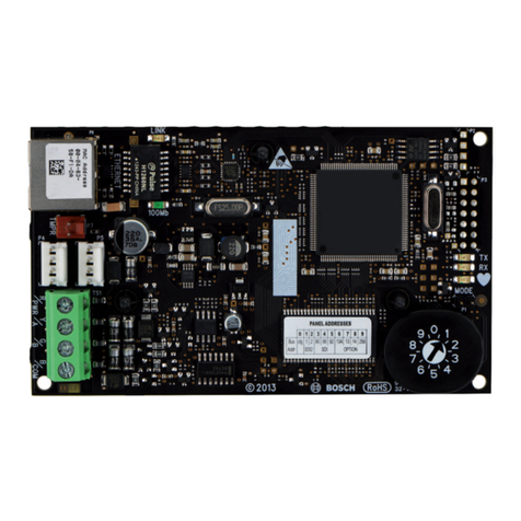
The B426 Ethernet Communication Module is a four-wire powered SDI,
SDI2, or Option bus device that provides two-way communication with
compatible control panels over IPv4 or IPv6 Ethernet networks.
The B426 on-board switch determines the bus address of the device.
Conguration of the B426 is performed through the B426 conguration
web pages. On SDI2 control panels, conguration can also be done on
the keypad or through Remote Programming Software (RPS).
Figure 1.1: Board overview
Callout ― Description
1 ― Ethernet RJ-45 port
2 ― Yellow LINK LED
3 ― Green 100MB LED
4 ― Address switch
5 ― Heartbeat LED (blue)
6 ― Data bus communication LEDs (TX and RX)
7 ― SDI2 terminal strip
(to control panel or additional modules)
8 ― SDI2 interconnect wiring connectors
(to control panel or additional modules)
9 ― Tamper switch connector
Bosch Security Systems, Inc.
130 Perinton Parkway
Fairport, NY 14450
USA
www.boschsecurity.com
© 2013 Bosch Security Systems, Inc. F.01U.281.209 | 02 | 2013.08
Copyright
This document is the intellectual property of Bosch Security Systems, Inc. and is protected by copyright. All rights reserved.
Trademarks
All hardware and software product names used in this document are likely to be registered trademarks and must be treated accordingly.
Bosch Security Systems, Inc. product manufacturing dates
Use the serial number located on the product label and refer to the Bosch Security Systems, Inc. website at
http://www.boschsecurity.com/datecodes/.
Dimensions 59.5 mm x 108 mm x 16 mm (2.19 in x 4.25 in x 0.629 in)
Voltage (operating) 12 VDC nominal
Current (maximum) 100 mA max
Connectors LAN/WAN: RJ-45 modular port (Ethernet)
Ethernet cable Category 5 or better unshielded twisted pair, 100 m (328 ft) max length
Interface IEEE 802.3
Data bus wire size 1.02 mm to 0.65 mm (18 AWG to 22 AWG)
Data bus wire length Maximum distance - Wire size:
150 m (500 ft) - 0.65 mm (22 AWG)
300 m (1000 ft) - 1.02 mm (18 AWG)
Web browser Microsoft Internet Explorer 6 or higher; Mozilla Firefox 3 or higher
Compatibility D9412, D7412, D7212, D9112
G Series Version 6.3 or higher
GV2 Series
GV3 Series
GV4 Series
B5512/B4512/B3512
8 | Specications
5 | LED descriptions
The B426 module includes the following on-board LEDs to assist
with troubleshooting issues (refer to Figure 1.1 for the location of the
LEDs):
– Heartbeat (system status). Refer to Table 5.1.
– Data Bus communication. Refer to Table 5.2
– Ethernet communication. Refer to Table 5.3.
Flash pattern Function
Flashes once
every 1 sec
Normal state: Indicates normal operation state.
3 quick ashes
every 1 sec
Communication error state: Indicates (the
module is in a “no communication state”)
resulting in an SDI2 communication error.
On Steady LED trouble state: Module is not powered
(for OFF Steady only), or some other
trouble condition prohibits the module from
controlling the heartbeat LED.
Off
Table 4.1: Heartbeat LED descriptions
Flash pattern Function
RX (Receive)
ashes
Occurs when the control panel bus receives a
message.
TX (Transmit)
ashes
Occurs when the control panel bus sends a
message.
Table 4.1: Data bus LEDs descriptions
LINK (yellow)
ash pattern
100mb (green)
ash pattern
Function
Off Off No Ethernet link
On Steady Off 10 BASE-T link
Flash Off 10 BASE-T activity
On Steady On Steady 100 BASE-T link
Flash On Steady 100 BASE-T activity
Table 4.1: Ethernet LINK and 100mb LEDs descriptions
7 | Certications
Region Certication Applicable control panels
US UL 365 – Police Station Connected Burglar Alarm Units and Systems B5512/B4512, GV4 Series, GV3 Series, GV2 Series
UL 609 – Local Burglar Alarm Units and Systems B5512/B4512, GV4 Series, GV3 Series, GV2 Series
UL 864 – Control Units and Accessories for Fire Alarm Systems
(Including NFPA 72)
GV4 Series, GV3 Series, GV2 Series, FPD-7024
UL 985 – Household Fire Warning System Units B5512/B4512, GV4 Series, GV3 Series, GV2 Series
UL 1023 – Household Burglar Alarm System Units B5512/B4512, GV4 Series, GV3 Series, GV2 Series
UL 1076 – Proprietary Burglar Alarm Units and Systems B5512/B4512, GV4 Series, GV3 Series, GV2 Series
UL 1610 – Central Station Burglar Alarm Units B5512/B4512, GV4 Series, GV3 Series, GV2 Series
FCC Part 15 Class B, NIST FIPS-197 AES Certication
(IP Communications)
B5512/B4512, GV4 Series, GV3 Series, GV2 Series, G Series,
DS7200, DS7400, Easy Series V3+, AMAX 2000
Canada CAN/ULC S303 - Local Burglar Alarm Units and Systems B5512/B4512, GV4 Series, GV3 Series, GV2 Series
CAN/ULC S304 - Signal Receiving Centre and Premise Alarm Control
Units
B5512/B4512, GV4 Series, GV3 Series, GV2 Series
ULC-ORD C1023 - Household Burglar Alarm System Units B5512/B4512, GV4 Series, GV3 Series, GV2 Series
ULC-ORD C1076 - Proprietary Burglar Alarm Units and
Systems
B5512/B4512, GV4 Series, GV3 Series, GV2 Series
ICES-003 - Digital Apparatus B5512/B4512, GV4 Series, GV3 Series, GV2 Series
When the tamper switch is activated (closed to open), the heartbeat
LED stays OFF for 3 sec before indicating the rmware version.
The LED pulses the major, minor, and micro digits of the rmware
version, with a 1 sec pause after each digit.
Flashing patterns do not start until the tamper is open (short is
removed). In the following is an example, the version 1.4.3 shows as
LED ashes:
[3 sec pause] *___****___*** [3 sec pause, then normal operation].
To show the rmware version using an LED ash pattern:
– If the optional tamper switch is installed:
With the enclosure door open, activate the tamper switch (push and
release the switch).
– If the optional tamper switch is NOT installed: Momentarily short
the tamper pins.
Refer to Figure 6.1 for an example of ash patterns.
6 | Show the rmware version
Figure 6.1: Firmware LED ash patterns
For complete installation, con guration, and testing instructions,
refer to the Conettix Ethernet Communication Module (B426)
Installation and Operation Guide provided on the supplied
CD-ROM.
en Installation Guide (UL)
Conettix Ethernet Communication
Module
B426

Other manuals for B426

6

Other Bosch Control Unit manuals

Bosch KTS Truck User manual

Bosch

Bosch KTS Truck User manual

Bosch D8128D User manual

Bosch

Bosch D8128D User manual

Bosch CRR 120 Setup guide

Bosch

Bosch CRR 120 Setup guide

Bosch Rexroth BTV 16 Technical manual

Bosch

Bosch Rexroth BTV 16 Technical manual

Bosch Rexroth SM 12 Operating instructions

Bosch

Bosch Rexroth SM 12 Operating instructions

Bosch CCU-Modul Operating manual

Bosch

Bosch CCU-Modul Operating manual

Bosch Sensortec Application Board 3.0 User manual

Bosch

Bosch Sensortec Application Board 3.0 User manual

Bosch POPEX B299 User manual

Bosch

Bosch POPEX B299 User manual

Bosch DCU 220 Setup guide

Bosch

Bosch DCU 220 Setup guide

Bosch FLM-420-01 User manual

Bosch

Bosch FLM-420-01 User manual

Bosch B426 User manual

Bosch

Bosch B426 User manual

Bosch Rexroth DBET User manual

Bosch

Bosch Rexroth DBET User manual

Bosch FLM-420-O2-D User manual

Bosch

Bosch FLM-420-O2-D User manual

Bosch Rexroth WMM6 Series User manual

Bosch

Bosch Rexroth WMM6 Series User manual

Bosch Rexroth ID 200/C-PDP User manual

Bosch

Bosch Rexroth ID 200/C-PDP User manual

Bosch KTS 5a Series User manual

Bosch

Bosch KTS 5a Series User manual

Bosch Rexroth MKK 12-40 User manual

Bosch

Bosch Rexroth MKK 12-40 User manual

Bosch PBK User manual

Bosch

Bosch PBK User manual

Bosch RM2-DP12 Operating and installation instructions

Bosch

Bosch RM2-DP12 Operating and installation instructions

Bosch KTS 5 Series User manual

Bosch

Bosch KTS 5 Series User manual

Bosch CR 20 RF User manual

Bosch

Bosch CR 20 RF User manual

Bosch ConnectModule BCM3100 User manual

Bosch

Bosch ConnectModule BCM3100 User manual

Bosch Rexroth IndraControl VCP 20.2 Technical manual

Bosch

Bosch Rexroth IndraControl VCP 20.2 Technical manual

Bosch Rexroth PSI 6500 Series Manual

Bosch

Bosch Rexroth PSI 6500 Series Manual

Popular Control Unit manuals by other brands

IFM ecomatDisplay CR1077 operating instructions

IFM

IFM ecomatDisplay CR1077 operating instructions

Advantech SOM-5899 user manual

Advantech

Advantech SOM-5899 user manual

DataComm 70-0020 Instruction and Installation Sheet

DataComm

DataComm 70-0020 Instruction and Installation Sheet

Arduino HM-11 user manual

Arduino

Arduino HM-11 user manual

IPS I0633SU0020PA-USB quick start guide

IPS

IPS I0633SU0020PA-USB quick start guide

theobroma systems RK3399-Q7 user manual

theobroma systems

theobroma systems RK3399-Q7 user manual

Hauber Elektronik 663-Window manual

Hauber Elektronik

Hauber Elektronik 663-Window manual

Sennheiser SIS 1019 A 20 Instructions for use

Sennheiser

Sennheiser SIS 1019 A 20 Instructions for use

GE C-800 Series installation guide

GE

GE C-800 Series installation guide

Baldwin Boxall BT10 operating instructions

Baldwin Boxall

Baldwin Boxall BT10 operating instructions

Cerlic BB2 manual

Cerlic

Cerlic BB2 manual

Hayward PBV series Installation, operation and maintenance instructions

Hayward

Hayward PBV series Installation, operation and maintenance instructions

Ebyte E78-915LN22S (6601) user manual

Ebyte

Ebyte E78-915LN22S (6601) user manual

CEBEK FM-2 quick guide

CEBEK

CEBEK FM-2 quick guide

CAME BPT DMI quick guide

CAME BPT

CAME BPT DMI quick guide

BFT PERSEO CBE quick start guide

BFT

BFT PERSEO CBE quick start guide

Freescale Semiconductor MC33493MOD Series Quick start user guide

Freescale Semiconductor

Freescale Semiconductor MC33493MOD Series Quick start user guide

Miele XKM 3200 WL LMD operating instructions

Miele

Miele XKM 3200 WL LMD operating instructions

manuals.online logo
manuals.online logoBrands
  • About & Mission
  • Contact us
  • Privacy Policy
  • Terms and Conditions

Copyright 2025 Manuals.Online. All Rights Reserved.