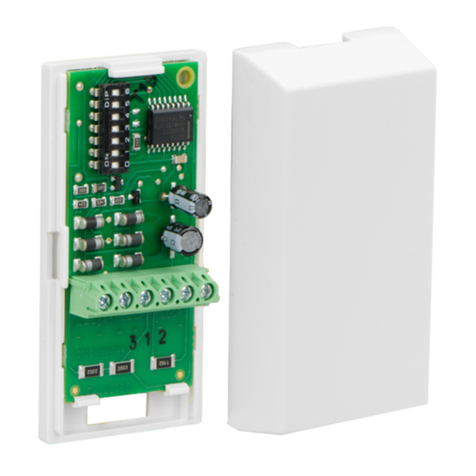
Bosch ICP-MAP5000-2 User manual
Other Bosch Control Unit manuals
Bosch
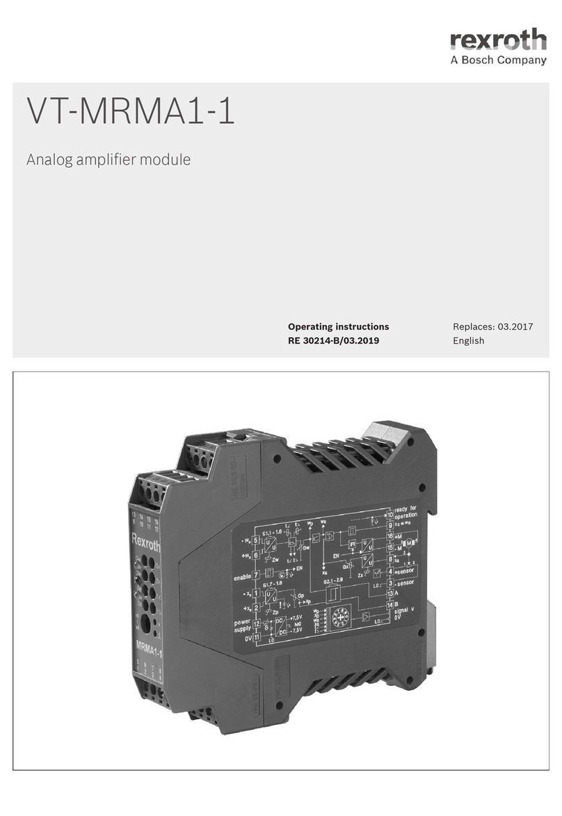
Bosch Rexroth VT-MRMA1-1 User manual
Bosch
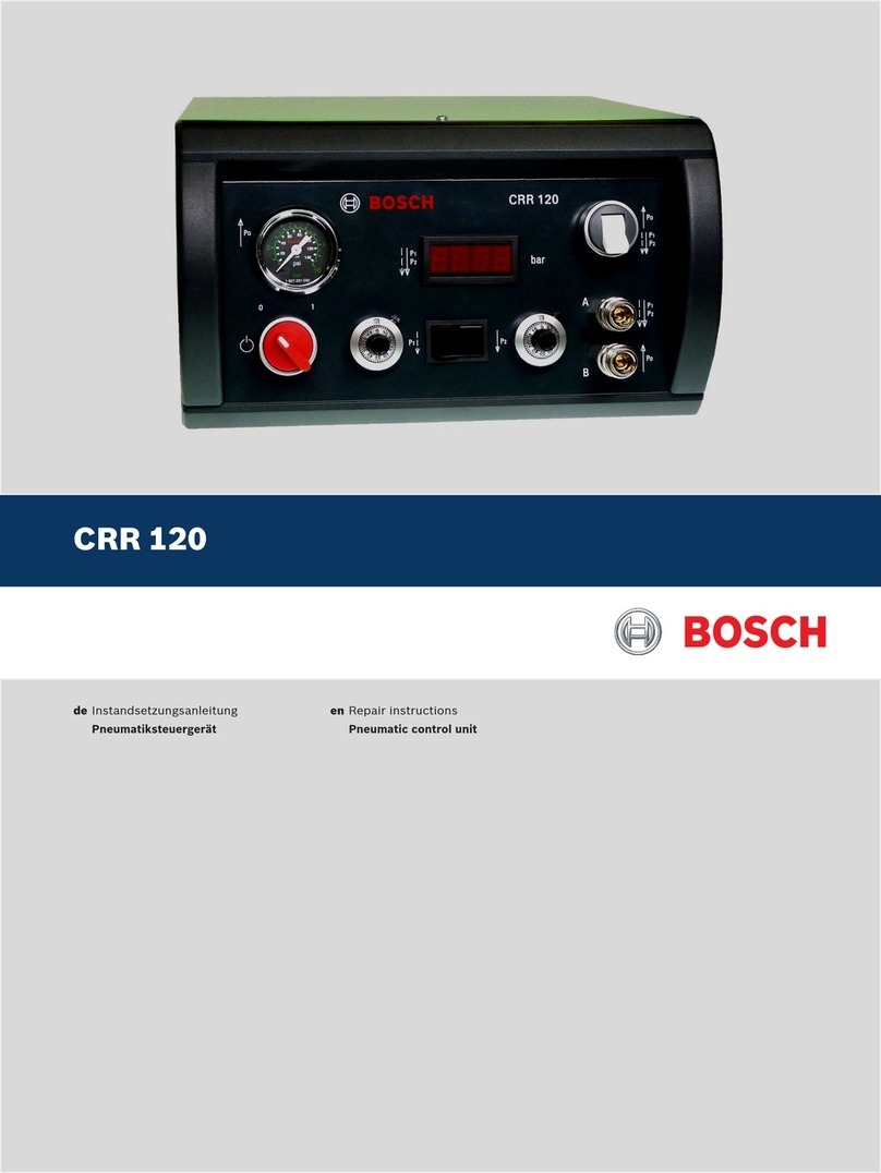
Bosch CRR 120 Setup guide

Bosch
Bosch CFB 840 User guide

Bosch
Bosch KTS Truck User manual
Bosch
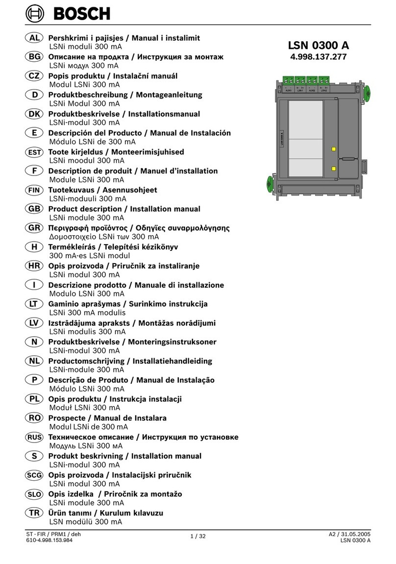
Bosch LSN 0300 A User manual
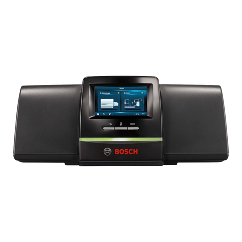
Bosch
Bosch Control 8313 Operating instructions
Bosch
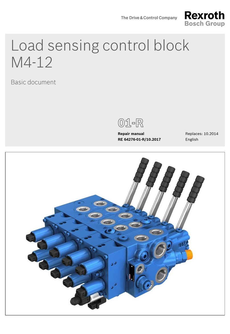
Bosch Rexroth M4-12 Operating instructions

Bosch
Bosch MC 400 User manual
Bosch
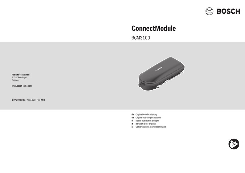
Bosch ConnectModule BCM3100 User manual
Bosch
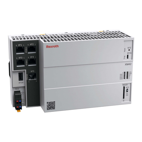
Bosch Rexroth IndraControl XM42 User manual

Bosch
Bosch Rexroth IndraControl L10 Technical manual

Bosch
Bosch DS7432 User manual
Bosch
Bosch RC 4001 User manual

Bosch
Bosch MED17.5.2 User manual
Bosch
Bosch rexroth DB20K.1X E Series User manual
Bosch
Bosch Rexroth FMS User manual
Bosch
Bosch Rexroth IndraControl VCP 05.2 Technical manual

Bosch
Bosch ACS 611 User manual
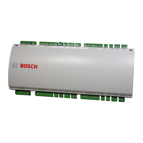
Bosch
Bosch AMC2 4W-EXT User manual

Bosch
Bosch MS 3 Sport GT3 Cup User manual
Popular Control Unit manuals by other brands

Festo
Festo Compact Performance CP-FB6-E Brief description

Elo TouchSystems
Elo TouchSystems DMS-SA19P-EXTME Quick installation guide

JS Automation
JS Automation MPC3034A user manual

JAUDT
JAUDT SW GII 6406 Series Translation of the original operating instructions

Spektrum
Spektrum Air Module System manual

BOC Edwards
BOC Edwards Q Series instruction manual

KHADAS
KHADAS BT Magic quick start

Etherma
Etherma eNEXHO-IL Assembly and operating instructions

PMFoundations
PMFoundations Attenuverter Assembly guide

GEA
GEA VARIVENT Operating instruction

Walther Systemtechnik
Walther Systemtechnik VMS-05 Assembly instructions

Altronix
Altronix LINQ8PD Installation and programming manual


