Tighten the two screws on the cover plate
of the drive module to lock the drive module in
its slot.
10.3 Removal of the Drive Module
Make sure that all power supplies are switched
off, the ‘DRV’ LED on the drive module is off,
and capacitors in the system are fully dis-
charged before you remove the drive module.
Loosen the two screws that hold the drive
module in the slot of the system housing. Gen-
tly pull the drive module out of the slot of the
system housing.
11 Commissioning
______________________________________
Damage to components
may occur if power on/off sequence is not in
the correct order.
Make sure that the 24V System power
supply is applied before the drive power
is applied.
Do not connect the drive power supply to
the “DP 0 NY4125” header of the system
housing while the drive power supply is
switched on.
Do not switch on/off the drive power
supply by connection/disconnecting the
“DP 0 NY4125” plug.
______________________________________
11.1 Logic Power Supply
Power supply for the logic of the drive module
is connected via the connector blocks at the
rear side of the drive module and is supplied by
the Motion Control Unit in the system housing.
11.2 Drive Power Supply
Power supply for the motors connected to the
drive module is connected via the connector
blocks at the rear side of the drive module and
is supplied via the “DP 0 NY4125” header of
the NY4063 system housing.
11.3 I/O Power Supply
Power supply for the digital I/O connected to
the drive module is connected via the connect-
or blocks at the rear side of the drive module
and is supplied via headers of the system hous-
ing.
11.4 Configuration
The flash memory on the Motion Control Unit
(MCU) contains the gateware for the logic on
the drive module. The flash memory on the
MCU also contains a bootloader to communi-
cate with the NYCe 4000 tools such as NYCe-
Configurator. With the tools you can download
from the PC to the MCU the required firmware
for the MCU and the required gateware for the
drive modules installed in the system housing.
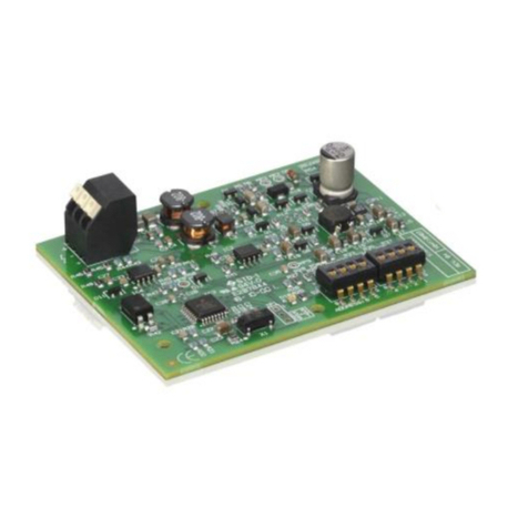
12 Description of the Drive Module
The drive module has two blocks of connectors
at the rear edge of the circuit board, which
connects the drive module to the backplane in
the system housing. All power supply connec-
tions and interface connections to other mod-
ules in the NYCe 4000 system housing are es-
tablished via these connector blocks.
The front side of the drive module has a
cover plate. On the cover plate is one LED vis-
ible. The LED is marked ‘DRV’.
13 Diagnosis
After the installation of the drive module in the
system housing (with an MCU installed), con-
nection of the power supply, you can check the
operation of the drive module.
The ‘DRV’ LED shows the status of the drive
module.
See the NYCe 4000 Hardware System
Manual for more information. Note that
NYCe 4000 software must be installed on the
PC.If the NYCe 4000 software is installed on
the PC, you can start the NYCeConfigurator
program and download the required gateware.
See the NYCe 4000 Tools Manual for more in-
formation.
“DRV” LED indication
(visible color)
Default setting when the drive module starts, power up.
Fatal error on the drive module, or gateware is not or
not correctlyloaded, or module not operational, because
a communication problem is detected.
Gateware loaded, but node not yet operational, because
other drive modules in the node are initializing.
Drive module is OK, but an overvoltage condition or
over temperature condition is detected, or a configured
motor can not run due to undervoltage.
-Overvoltage condition occurs at 40V.
-Over temperature condition occurs at 105 °C.
-Undervoltage condition occurs at 12V.
