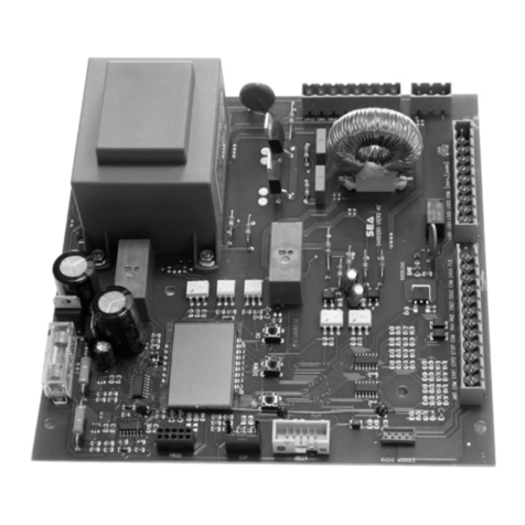
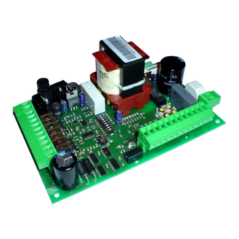
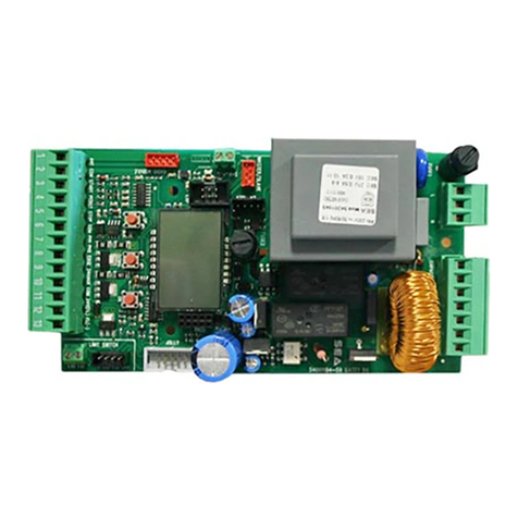
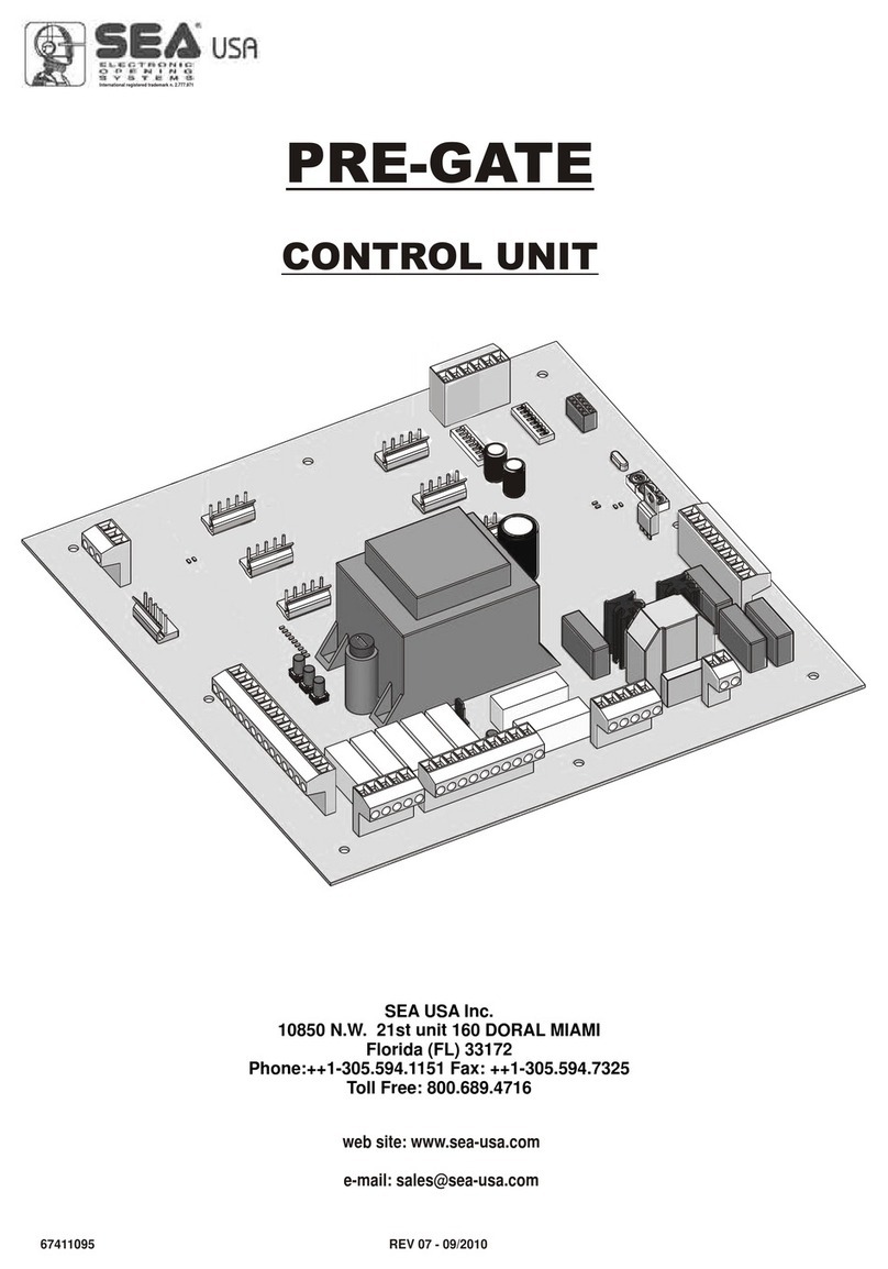
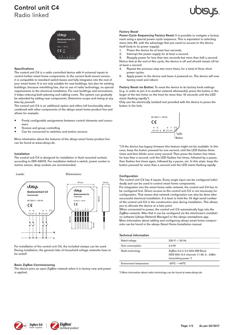
SEA USER 1-24V User manual

USER 1 - 24V
24V ELECTRONIC CONTROL UNIT FOR SLIDING GATES AND BARRIERS
2300A24
REV 01 - 05/2011
International registered trademark n. 2.777.971
SEA USA Inc.
10850 N.W. 21st unit 160 DORAL MIAMI
Florida (FL) 33172 USA
Tel. -
Toll free:
:++1-305.594.1151 ++1-305.594.7325
800.689.4716
web site: www.sea-usa.com
e-mail: [email protected]
67411071

GENERAL SAFETY REGULATIONS FOR THE INSTALLER
• The installer has to read and understand the functioning of this operator system, its safety features and knowing the manual function in case of emergency.
• Do not modify in any way the automated system’s components. SEA USA Inc. declines all liability concerning the automated system’s security and efficiency if
the used components are not produced by SEAUSAInc. For maintenance, strictly use original SEAUSA Inc. spare parts.
• The installer shall supply the user with all information concerning the proper operation of the product, the system’s manual functioning in case of emergency and
shall hand over to the user the warnings handbook supplied with the product.
• SEA USA Inc. recommends the system to have reversing sensor (encoder) on the drive shaft of the motor. In case of swing/linear/in-ground hydraulic
operators/barriers, SEA USA Inc. recommends to install the SAFETY GATE as an additional reversing sensor. Reversing devices are required to prevent the
system from closing on vehicular traffic and/or help to prevent injuries to pedestrians.
• It is recommended to use indicator-lights as well as warning signs for every system. Both should be visible on each side of the gate and well fixed on the frame
structure.
• Do not leave packing materials (plastic, polystyrene, etc.) within children’s reach, as they are potential sources of danger.
• For products having an emergency release, it is recommended to use it only when the gate/barrier is closed.
• Remove all locks connected to the gates before installing the operator.
• Locate the control button: (a) within sight of door, (b) at minimum height of 5 feet so that small children are not able to reach it, and (c) away from all moving parts
of the door.
• Install entrapment Warning Label next to the control button in a prominent location. Attach marking next to the emegency release.
• Do not employ for any reason automatic closing devices (such as timer, loop sensors, or similar), and do not connect any other activation devices.
GENERAL SAFETY REGULATION FOR THE USER
• Sea strongly recommends to follow these instructions literally to prevent very serious damages to persons. This product was designed and built strictly for the
use indicated in this documentation. Any other use, not expressly indicated here, could compromise the good condition/operation of the product and/or be a
source of danger. SEAUSA Inc. declines all liability caused by improper use or different use in respect to the intended one.
• Only qualified personnel can install, repair and periodically check this equipment.
• The User must not attempt to repair or to take direct action on the system and must solely contact qualified SEA personnel or SEA service centres. User can
apply only the emergency manual function.
• The system has been designed for the control of vehicular traffic only. Pedestrians or bicycles must have a separate access opening.
• Do not allow children or adults to stay near the product while it is operating. The application cannot be used by children, by people with reduced physical, mental
or sensorial capacity, or by people without experience or necessary training. Keep remote controls or other pulse generators away from children to prevent
involuntary activation of the system.
• Transit through the leaves or barrier is allowed only when the gate/barrier is fully open. Operate system only if it is fully visible, and free of obstructions.
• For products having an emergency release use it only when the door/barrier is closed.
ELECTRICAL CONNECTIONS - SAFETY INSTRUCTIONS
• Disconnect the battery back up, if included, before disconnecting main power supply.
•Always disconnect power supply during installation or servicing of the product.
•All electrical connections from the control panel’s to the operator’s must be made in a waterproof junction box.
• The system requires a separate power supply circuit. Check that the main power supply circuit breakers are separated, intended solely for this equipment and
rated for 15AMPS. Visually check that the circuit breakers are in OFF position and mark the circuit breakers USED prior to installation.
• Permanent wiring must be used and installed to the operator as required by local electrical codes and It is recommended to do by a licensed electrician.
It is also recommended to check the local building code requirements before making any type of wiring to be sure that all wirings comply with them. Local building
codes will take precedence. It is recommended to use different colours for all wirings’codes.
• Distance for low voltage control wires, i.e., open input, single leaf, open input and stop input, can run up to 3000 feet with 18AWG wire. Low voltage controls and
communication wirings must all be separated by a minimum of 1 foot from high voltage power wiring and in a separate conduit.
GROUNDING
• Good grounding and proper surge suppression are an integral part of proper installation for all operator systems. One or all of the followings may require surge
suppressors: high voltage power lines, low voltage power lines, telephone lines, data lines, low voltage control lines and loops. Quantity of surge suppression
requires depends on susceptibility of the area to lightning and power surges. Good grounding is essential to realize maximum protection.
• If the circuit breaker box is located close to the gate/barrier operator system, for example, in a guardhouse, then the ground from that circuit can be used to
ground the gate operator system. Eliminate all 90° bends in ground wires and keep a minimum distance of three feet between the surge suppressor and the
equipment to protect.
• If the power source or circuit breaker box is not located close to the operator system, an Isolated Ground Zone (IGZ) must be created. An IGZ is an imaginary
circle drawn around the operator system. An IGZ can also be created, if the circuit breaker box is located close to the operator system. The operator system not
only includes the operator and control panel, but all accessories and devices associated with it at that controlled entry point. This includes loop detectors, card
readers, digital entries, telephone entries, any device that has or requires grounding and all the surge suppressors. The ground bus is a common ground point
called Single Point Ground (SPG). It is used to bond all the equipments and devices grounded in the IGZ together. The SPG is very important because it helps to
eliminate different ground potentials that can be present on the equipment and that could cause damages even with surge suppressors.
• Do not use or connect the ground wire coming from the circuit breaker box. By using an Isolated Ground Zone, you have to separate the operator system from
the house or building ground. This eliminates ground potentials. It is recommended the ground bus to be located in a separate NEMAtype enclosure. All grounds
will be tied to this ground bus.
• Equipment ground wire should be of minimum 12AWG. The main ground wire from the bus bar to the ground rod should be an 8 or 6AWG copper wire.
Ground rod should be minimum 10 feet in length, (length depends on local soil conditions).
• For more information, regarding good grounding practices check: National Electric Code art. 250; IEEE Emerald Book, standard 100; International Association
of Electric Inspectors.
• Where possible, install the opener control 7 feet or more above the floor. For products having an emergency release, mount the emergency release 6 feet above
the floor.
USER 1 - 24V
International registered trademark n. 2.777.971
67411071
2REV 01 - 05/2011

INSTALLATION WARNINGS
• For gate operators: install only when
A. The operator is appropriate for the gate’s construction and usage Class.
B. All opening spaces on the wall of the horizontal slide gate are guarded or screened from the bottom of the gate to a minimum of 4
feet (1m) above the ground so that it could be possible to keep on the entire surface of the wall a minimum distance of 2-1/4 (57,15mm) inches from the
gate and the wall on which the gate runs.
C.All exposed pinch points are eliminated or guarded
D. Guarding is supplied for exposed rollers.
E. Check if the gate works freely in both directions before installing the gate operator system. Any necessary repair to the gate must be done
before installing the equipment. Swinging gate shall not open into public access areas.
• The operator systems must be installed in a proper place to prevent contacts with adjacent structures in opening and closing. Watch out to install the system so
that users could have full view of the area.
• For operators using non-contact sensors:
A. See instructions on the placement of non-contact sensors for each Type of application.
B. Watch out to reduce the risk of nuisance tripping of the sensor.
C. One or more non-contact sensors shall be located where the risk of entrapment or obstruction exists, such as the perimeter reachable by a moving
gate or barrier.
• For operators utilizing contact sensors:
A. One or more contact sensors must be located where the risk of entrapment or obstruction exists, such as the operators’ edges. They
should be installed both inside and outside the operator’s edge.
B. A hardwired contact sensor must be installed, watching out to arrange its wiring so that the communication between the sensor and the
operator should not be subjected to mechanical damage.
C. A wireless contact sensor such as a radio frequency (RF) signal transmitter must be located where the signal’s transmission cannot be
obstructed by structures or natural landscaping.
• Controls should be far enough from the gate or barrier so that the user is prevented from coming in contact with them while operating the controls. Controls are
intended to be used to reset an operator after 2 sequential activations of the entrapment protection device and must be located in the line-of-sight of the outdoor.
Install a security feature If controls are easily accessible, to prevent unauthorized use.
AFTER INSTALLATION
• Check that: the open and close force are properly adjusted; the piston does not bottom out in either direction, the breather screws have been removed, the
positive stops used are sufficient for stopping the gate properly, all the pinch points and potential entrapment areas are reduced.
• Check and test all reversing devices.
• The installer should instruct user on the operator system’s proper operation. They should together review the basic functions of the reversing devices and how to
periodically test them. Reversing devices include one or more of the followings: reversing loops, photocells, reversing edges, etc. The installer has to instruct
user on how to remove the operator system from service, on shutting power off on the service panel and how to use the operator system manually.
GENERAL ENTRAPMENT PROVISIONS
A vehicular operator must be installed with one independent primary and one independent secondary means at least to protect against entrapment
(see Table A):
Note: The same type of device shall not be utilized for both the primary and secondary entrapment protection means. The use of a single device to cover both
the opening and closing directions is in accordance with the requirements; however, a single device is not required to cover both directions. A combination of
one Type B1 for one direction and one Type B2 for the other direction is the equivalent of one device, for the purpose of complying with the requirements of
either the primary or secondary entrapment protection means.
Entrapment protection types
TypeA: Inherent entrapment sensing system.
Type B1: Provision for connection of a non-contact sensor (photoelectric or equivalent).
Type B2: Provision for connection of a contact sensor (edge device or equivalent).
Type C: Inherent adjustable clutch or pressure relief device.
Type D: Provision for connection of an actuating device requiring continuous pressure to maintain opening or closing motion of the gate.
Type E: An inherent audio alarm.
CLASS OF OPERATORS
RESIDENTIAL VEHICULAR GATE OPERATOR - CLASS I - A vehicular operator (or system) intended for use in a home of one-to four, single-family dwelling, or
a garage or parking area associated therewith.
COMMERCIAL/GENERAL ACCESS VEHICULAR OPERATOR - CLASS II - A vehicular operator (or system) intended for use in a commercial location or
building such as multi-family housing unit (five or more single family units), hotel, garage, retail store, or other building servicing the public.
INDUSTRIAL/LIMITED ACCESS VEHICULAR OPERATOR - CLASS III - A vehicular operator (or system) intended for use in an industrial location or building
such as a factory or loading dock area or other locations not intended to service the public, in which unauthorized access is prevented via supervision by security
personnel.
USER 1 - 24V
International registered trademark n. 2.777.971
67411071 3
REV 01 - 05/2011

USER 1 - 24V
M4
1 2
M1
M3
M1
1
1
2
23
+-
M2
1 2
+-
24V Accessories Max 200 mA
hiVFlas ng lamp 2415W
S
V at ery arge
28 B tch r
Posit ve bte y
ia t r
Negativebattery charger
Only with battery charger
card
(Cod.23101105)
M5
1 2
Co mon
m
na
Ante n
M6
1 2
ST R
A T
om
C mon
M7
1 2
SARPedT T .
M8
1 2
de
Safetyeg
m
Comon
om
C mon
International registered trademark n. 2.777.971
CONNECTIONS
67411071
4REV 01 - 05/2011

1 2
BUS
M11
USER 1 - 24V
CONNECTIONS
de1 ( i eEncorWht )
Cmo
omn
M9
1 2
m on
Co m
SO
P
T
JOLLY
RADIO MODULE
Receiver module connector
POWER
E ode 1 n)nc r
(Gree
N.C.
24V feed connector
PROGR RX
ENCODER
Connector Programmer Jolly
Connector programmer OPEN
Potocell
h
M10
1 2
DIP SWITCH
ON
ON
1
3
2
4
ON
ON
osAutomaticcling
Motor ever ionr s
Dip Swihacti ati n
tcv o StartinPause
mon
Co m
Com on
m
International registered trademark n. 2.777.971
67411071 5
12V
Common
h
Liw Op.1
mit s itc
iim switchCl.1
L t
LIMIT SWITCH
4V
+2
1 2 3 4
REV 01 - 05/2011

USER 1 - 24V
INDEX
COMPONENTS’ DESCRIPTION ..................................................................................................7
GENERAL INFORMATION ...........................................................................................................8
START, STOP, PEDESTRIAN START, ANTENNA, PHOTOCELL CONNECTIONS.....................9
ENCODER, LIMIT SWITCH, WARNING LAMP, EDGE..............................................................10
POWER SUPPLY AND MOTORS CONNECTIONS ..................................................................11
SELFLEARNING DEFAULT SETTING........................................................................................11
WORKING TIMES SELFLEARNING ..........................................................................................12
SETTINGS’ SELECTION ............................................................................................................13
EXTERNAL RECEIVER CONNECTION AND RADIO TRANSMITTER LEARNING ..................14
FUNCTIONING LOGICS.............................................................................................................15
BUS SYSTEM DESCRIPTION ...................................................................................................15
MASTER SLAVE FUNCTION......................................................................................................16
PROGRAMMER JOLLY PARAMETERS ADJUSTMENT............................................................ 17
CONNECTION OF BATTERIES .................................................................................................19
ALARMS DESCRIPTION............................................................................................................19
TROUBLE SHOOTING ...............................................................................................................20
SALES CONDITIONS .................................................................................................................21
6
International registered trademark n. 2.777.971
67411071 REV 01 - 05/2011
DESCRIPTION OF THE COMPONENTS
LED1 = Encoder ON - Encoder OFF
LED2 = Pause adjustment
LED3 = TX Programming
LED4 = Slowdown speed adjustment
LED5 = Functioning logics
LED6 = Motors speed
LED7 = Encoder
LED8 = Limit switch in opening
LED9 = Limit switch in closing
LED10 A = Led for SET
LED11 B = Led for SET
LED12 C = Led for SET
LED13 = Start
LED14 = Pedestrian Start
LED15 = Security edge
LED16 = Stop
LED17 = Photo
LED18 = Indicator BUS
LED19 = Battery Ok
LED20 = Unloaded Battery
LED21 = Broken fuse
LED22 = 24Vaux condition
LED23 = Warning lamp condition
SET = Setting
MENU = Selection
7
M1 = Connection to battery charger
M2 = 24Vaux exit
M3 = Motor power supply
M4 = Warning lamp 24V 15W
M5 = Antenna
M6 = Start
M7 = Pedestrian start
M8 = Security edge
M9 = Stop
M10 = Photocell
M11 = BUS
CNE = Encoder connector
CNF = Limit switch connector
CMD = Jolly programmer connector
CMR = Receiver module connector
CALM = 24V power supply connector
CPO = Programmer connector OPEN
CRC = Control unit reprogramming connector
µC = Micro-controller
DSW1 = Automatic closing/Start in pause
DSW2 = Opening direction/Dip Switch activation
USER 1 - 24V
M1 M2 M3 M4
- S +
24Vaux
Motor
Light
CMR
CMD
ENCODER
LIMIT SWITCH
DSW1
DSW2
SET
MENU
M5 M6 M7 M8 M9 M10 M11
Ant. Start Ped. Edge Stop Photo Bus
CALM
LED 22
LED 23
LED 8
LED 9
LED 7
LED 10
LED 11
LED 12
LED 1
LED 2
LED 3
LED 4
LED 5
LED 6
LED 19
LED 20
LED 18
LED 14
LED 15
LED 16
LED 17
LED 13
LED 21
SET
MENU
GATE TYPE
PAUSE
TX
SLOW D. SPEED
LOGIC
SPEED
SET LEDS
A B C
BATT OK BATT LOW
ENCODER
START PED S.EDGE STOP
PHOTO
BUS
FLASH
SET MOT PWR
FLASH
SET MOT PWR
LSC
LSO
FUSE
LIGHT
24Vaux
1
2
3
4
FLASH
SET MOT TYPE
FLASH
SET MOT TYPE
SET FUNCTION
AUTO CLOSE
START ON PAUSE
DIRECTION REVERSE
DIP DISABLE
1
2
3
4
International registered trademark n. 2.777.971
67411071 REV 01 - 05/2011
GENERAL INFORMATION
The information in this section of the manual are only for technicians or for qualified or authorized installers.
GENERAL CHARACTERISTICS
The USER 1 24V control unit has been designed to manage one low voltage motor with or without electronic limit switches.
It is of very small dimensions and besides the possibility to adjust motor speed, amperemetric anti squeezing sensitivity, leaf
delay in closing, pausing time, it is also possible to manage a display, through which it is possible to control a lot of management
functions and the maintenance of the control unit. The most important change however concerns the presence of a BUS
connector with two wires, through which it is possible to connect accessories as photocells, flashing lamp, key switch and so
on,... connecting only two cables with the control unit. The self- learning of working time can be done automatically.
8
TECHNICAL SPECIFICATIONS
Control unit power supply
Absorption in stand by
Max. motor charge
Max. accessories charge
Max. Flash light charge
Environment temperature
Protection fuse (24V accessories)
Function logic
Opening/closing time
Time of pause
Thrust
Slow down
Input on connecting terminal
Output on connecting terminal
Board dimensions
Specifications of optional batteries
Specifications of external enclosure
Special accessories
24 V
90 mA
90 W x 2
24V 250mA
24V 15W max.
-4°F +131°F
F1 (2A)
Automatic/Step by Step 1/S. By Step 2/Sec./Dead man
In selflearning in programming phase
Adjustable
Adjustable Opening and Closing
Adjustable
Battery power supply / Total opening / Pedestrian
opening adjustable / Edge/ Stop / Limit switch
opening and closing / Encoder/ BUS accessories
Power supply accessories 24V / Motors 24V /
Flashing lamp 24V / BUS
156 x 100 mm
24V Pb 2Ah min.
305 x 225 x 125 mm - Ip55
Battery charger card (cod.23101105), Relay card
for courtesy light or bolt lock (cod.23101106),
Programmer JOLLY (cod.23105276), Programmer
OPEN (cod.23105290), Photocell SUNSET BUS
(cod.23102075)
USER 1 - 24V
International registered trademark n. 2.777.971
67411071 REV 01 - 05/2011
START (N.O.)
An impulse given to this contact opens and closes the automation depending onthe selected logic It
can be given by a key switch, a keypad, etc. To connect the other devices refer to the related
instructions leaflets. (ie. loop detectors and proximity switches)
Note1: In DEAD MAN logic it is necessary to keep pressed the Start for the opening of the
automation.
PEDESTRIAN START (N.O.)
To obtain a partial opening connect the key-button wires as in the figure. It is possible to connect other
command devices (push button board, radio receiver, keypad).
Note1: The contact for partial opening is a N.O. Contact (Normally open)
Nota2: In manual logic it is necessary to keep pressed the Start Ped. To re-close the automation.
STOP (N.C.)
The pressure on this button immediately stops the motor in any condition/position. A start command
is needed to re-start the movement.
After a stop the motor always re-starts in closing.
Notice: If the stop button is not used it is not necessery to close the N.C. contact between the clamps
1 and 2 of M9 as the absence of the stop is revealed during the selflearning phase of the times.
N.O.
-
12
12
M7
N.C.
-
1 2
1 2
M9
N.O.
-
1 2
1 2
M6
Can be activated through the Jolly programmer or modifying either the PHOTO entry or the PEDESTRIAN entry.
In both cases it’s a N.O. contact which provoques the opening of the automation keeping it open until it is
activated. When it’s released, the gate attends the set pausing time and executes the reclosing.
Note2: When activated on the pedestrian entry, the pedestrian will be disabled also on the radio transmitter.
Note3: In case of intervention of a security device during the timer (Stop, Ammeter, Edge), to restore the
movement it will be necessary to give a start impulse.
Note4: In case of no power supply with open gate and active Timer the control unit will restore its use, otherwise
if during restore of the power supply the TIMER is not activated it will be necessary to give a start impulse for
the reclosing.
JOLLY OPTIONS
Activation TIMER: this entry can be transformed into TIMER (See TIMER)
Pedestrian opening space : Linearly adjustable from 30% to 100%.
START - STOP - PEDESTRIAN START - ANTENNA -
PHOTOCELL
Photocell 1 Connection
When the ray of the photocell is crossed, and the automation is in phase of closing it reverses its
movement.
Note: If the photocell is not connected, put a jumper between the clamps 1 and 2 of (M10).
+ = 24V - = 0V C = Connection Com = Common
The photocell is also usable in connection with BUS photocells.
JOLLY OPTION
TIMER
M2
5M M6 M7 M9
M0
1
USER 1 - 24V
12
12
M5
GND
12
12
M2
RX
TX
Com
N. .C
12
12
M10
-+-+
-
+ 24V
24Vaux max 200 mA
JOLLY OPTION
Through the Jolly programmer it is
possible to choose when having
tension on the 24Vaux output. The
options are: always, only during
opening, only during cycle, only
before opening or only during pause.
JOLLY OPTIONS
FOTOCLOSE activation: If activated when the photocell is crossed during the pause, the
gate interrupts the pause and immediately closes again.
TIMER activation: If the entry is activated it turns into a N.O. entry with TIMER function (see TIMER).
Fotoopen activation: If activated the photocell blocks the movement as long as it’s busy, when
released it opens.
FOTO PARK activation: in opening it is not active; when during the pause ”closing with photo” and
“automatic closing” are activated it commands the closing when released, otherwise it’s not active; in
closing it stops the movement as long as it is busy, when released the closing continues.
FOTO STOP activation: When activated before the opening the photocell blocks the automation as
long as it is busy, during the opening it will be ignored. In closing the intervention of the photocell causes
the reopening. ANTENNA
Connect the antenna
as in the figure.
9
International registered trademark n. 2.777.971
67411071 REV 01 - 05/2011
It is possible to connect an active safety edge on the
terminal M8. If this device is pressed it opens the
contact causing a partial inversion of the movement
both in opening and in closing. If not used bridge
the contacts 1 and 2 of M8. Note: contact N.C.
Limit switch
For the functioning the presence of both limit
switches in closing and in opening is necessary.
Encoder / Ammeter sensor
The encoder is a device that allows to reveal possible obstacles during the opening and the closing of
the gate. When this device intervenes in opening it causes the inversion of the movement for around
a second, if it intervenes in closing it causes the total reopening.
Note 1: Such function is active through an ammeter sensor on the control board. It is not
necessary to mount any external devices for the respect of legislation.
Note2: The ammeter sensitivity is adjustable both in opening and in closing through the
JOLLY terminal. On the control unit the torque can be adjusted in 4 steps: low, middle,
middle high, high and will be the same in opening and closing. With high torque the gate
reverses after 5 seconds.
Attention: after each intervention of the ammeter sensor it is necessary to give a start impulse
to restore the movement.
Costa di sicurezza
1 2
M8
For the right functioning of the limit switch, the movement direction of the motor and the
respective busy limit switches must correspond. Through DIP3 it is possible to
exchange contemporarily the direction of the motor and of the limit switches.
Note: if during programming phase the motor and limit switch times should not
be in phase between them, the gate will start in closing, it stops and will not
complete the selflearning of the times, at this point it will be necessary to
switch off the tension and to invert the cables of the motor and to eventually
exchange the motor direction on DIP 3. The first movement in selflearning must
always be executed in closing.
Com = Common
C = Contact
M4
1 2
1 2
JOLLY functions:
1) With the Jolly programmer such function is tied up to the presence of at least
one limit switch and it’s possible to activate the function anti-intrusion. When the
limit switch is free it forces the motor to re-close.
2) With the Jolly programmer it is possible to exchange the motor and the limit
switch without setting DIP3 of the control unit.
JOLLY functions:
It is possible to activate a pre-flashing of 3 seconds before activating the automation, on setting pre-
flashing on ON, through the Jolly programmer. Furthermore from the flashing lamp it is possible to verify
some alarm signals. See alarms indications.
Through the Jolly programmer it is possible to set this exit with fixed flashing also when the gate is not
moving or it is possible to change this exit into control lamp. In such case all the indications of alarm
remain on the warning lamp as long as they are active.
JOLLY FUNCTIONS:
It is possible to activate the balanced edge 8K2, in this
case the edge contact will be controled by a specific
value of resistance revealing the eventuel unintentional
short circuit of the device. In case of an unbalance of the
device the corresponding led of the terminal board M8
will flash quickly.
ENCODER - LIMIT SWITCH
JOLLY functions: With the JOLLY programmer the torque parameters can be adjusted linearly
from 10% to 100% on each single motor. Furthermore, they are differentiable between opening and
closing.
Flashing Lamp 24V 15W (Warning lamp )
The warning lamp advises that the automatic gate is moving with 1 flash /second in opening and 2
flashes / second in closing. During pause it remains fixed on.
Connect the cables of the warning lamp as shown in the figure. The pre-flashing function can be
activated with the Jolly terminal or with Led 4 of the menu through the SET and MENU buttons.
SECURITY EDGE AND WARNING LAMP
USER 1 - 24V
Limit
Switch
M4
M8
Limit
Switch
10
International registered trademark n. 2.777.971
67411071 REV 01 - 05/2011
USER 1 - 24V
11
International registered trademark n. 2.777.971
67411071
MOTOR POWER SUPPLY
3,6 A delayed fuse on 230V ~ power supply .
6,3A delayed fuse on 115V ~ power supply.
Power input
Input for the connection of the electric power.
P = PHASE - LIVE
N = NEUTRAL
G = GROUND
NOTICE: for the connection to the
electric power see the law in force.
M3
2
1
G N P
G N
115V~
o
230V~
P
M+M-
M3
1 2
Motor
connection
P N G
M+ M-
The control unit is pre-set with the default settings, to learn the working times it is sufficient to press the Menu button once
and to hold pressed the SET buttonuntil the motors start in closing. The settings of DEFAULT are: AUTOMATIC LOGIC,
ENCODER OFF, SPEED 80% , PRE-FLASHING OFF, PAUSE 10S., TORQUE 75%, SLOWDOWN SPEED 40%, LEARNING SPEED 80%,
ACCELERATION 70%, DECELARATION 30%, LEAF STROKE OFF, ANTI-INTRUSION OFF, SELFTEST OFF, PEDESTRIAN 30%,
PHOTO OPENING OFF, MAX CYCLES 100000, SLIDING MOTOR TYPE, WARNING LAMP NORMAL, PHOTO/TIMER OFF,
PEDESTRIAN/TIMER OFF, CLOS.FOTO OFF, BALANCED EDGE OFF, 24Vaux ALWAYS, START IN PAUSE OFF, AUTOMATIC
CLOSING OFF. IF YOU WANT TO RESTORE THE DEFAULT SETTINGS JUST SWITCH ON THE CONTROL UNIT KEEPING PRESSED
THE BOUTONS MENU AND SET CONTEMPORARILY.
SELFLEARNING WITH DEFAULT PARAMETERS
5 m
4 m
3 m
For the application on the VERG it is recommended
to use the speed levels indicated on the following
board:
LED 12C RED
LED 10A GREEN
LED 11B YELLOW
CONFIGURATION FOR VERG
M3
P N G
REV 01 - 05/2011
A) Select LED 1 of the self-learning through the MENU button, with LED 1 turned on press button SET to choose the function
modality: -Led L10 A green on = Encoder ON -Led L11 B yellow ON = Encoder OFF
B) Once the functioning modality has been chosen, always with Led10 A switched on, hold pressed SET up to the departure of the
motors in closing and then release the button.
GREEN
YELLOW
RED
WORKING TIMES SELF LEARNING
Note1: it is not necessary to put a jumper between the STOP, PHOTOCELL contacts if they are not used. If
they are used during selflearning phase they must stay (N.C.).
Note2: If accessories are connected on the BUS, align the photocells before programming, as shown in the
description of the BUS system.
1) Make sure that each accessory (photocells, push buttons, and so on) works properly.
2)If necessary adjust the self-learning speed through the palm user.
3)Disconnect the power supply (Fig. 1), release the motor (Fig. 2) and put the leaves manually next to the
stop in closing (Fig. 3-4). Reset the mechanical lock (Fig. 5)
4) Connect the control board to the power supply (Fig.6).
Fig. 1
FF
O
5) Select the desired type of motor; use as shown on pag. 28 or through JOLLY programmer.
6) Press the button “SET” until the led of the color corresponding to the type of application (Encoder ON, Encoder OFF) switches
on.
7) Hold pressed the button “SET” until the motor starts in closing and then release the button.
Note: If FOTOBUS are present, check their alignment and give a new impulse on SET to start the programming.
Note: If the motor starts in opening, switch of the power supply and set DIP 3 on ON or if you have a Jolly terminal, activate the
motor and limit switch exchange function. If the motor starts in closing and stops, switch off the power supply and invert the cable
of the motor, afterwards repeat the procedure starting from step 4.
Note: If you do not have a Jolly terminal the functions of the DIPs on board of the control unit can be activated setting DIP4 on ON.
If DIP4 is activated the functions which can be activated through DIP cannot be changed through the Jolly terminal.
8) The motor will close with the set speed.
9) After having reached the limit switch of closing it automatically will execute an opening cycle (Fig.7). After having reached the
limit switch in opening it will automatically execute a closing cycle.
10) Wait for the end of the closing of the leaf (Fig.8). The self-learning is done.
B) Press the “IMP” button till the Led of the colour
which corresponds to the type of installation (Encoder
ON or Encoder OFF) turnes on.
Keep pressed the button “SET” till the departure of the
motor in closing and then release the button.
A) Press the “Menu” button so that to turn on the LED1
JOLLY functions:
1) With the JOLLY
programmer it is possible to start the
programming without using the MENU
and SET bouton.
2) With the JOLLY programmer it is
possible to choose the type of motor
and the type of application without
using the MENU and SET boutons.
USER 1 - 24V
Fig.6
ON
A
Fig. 2 Fig. 5
Fig. 7
Fig. 3 Fig. 8
LED1
LED10 A
LED11 B
LED12 C
SET
MENU
PROGRAMMING
Fig. 4
12
International registered trademark n. 2.777.971
67411071 REV 01 - 05/2011

USER 1 - 24V
13
International registered trademark n. 2.777.971
67411071
SELECTION OF THE SETTINGS
The adjustments of the control unit are executed through the buttons "MENU" and "SET” .
Pressing the "MENU” button you select the Leds corresponding to the various functions to be set, pressing the “SET” button you select the leds
corresponding to the desired values inside every single function.
Selecting LED 2 with the“MENU" button you enter into pausing time regulation, with LED 2 turned on, hold pressed the selected button "SET” for the desired time of pause.
According to the colour that the leds 10 A,11 B and 12 C will assume it will be possible to have an order of the length of the set time of pause. If the button is released and pressed
again the time of pause will be annulled.
Led L10 A green turned on Time of pause <15 S.
Led L11B yellow turned on Time of pause <45 S.
Led L12 C red turned on Time of break >45 S. up to 180 S.
Selecting LED 4 with the “MENU" button you enter into the slowdown speed adjustment, with LED 4 turned on, press the button "SET” till to select the desired leaf delay,
observing the colours of the leds 10A, 11 B and 12 C.
Led L10 A green slowdown speed 30%
Led L11 B yellow slowdown speed 35%
Led L10 A - Led L11 B Green-yellow slowdown speed 45%
Led L10 A - Led L12 C Green-red slowdown speed 50%
Selecting LED 5 with the “MENU" button you enter into the choice of the functioning logics, with LED 5 turned on, press the button "SET” till to select the desired logic, observing
the colours of the Leds 10A, 11 B and 12 C.
Led L10 A green on dead man logic
Led L11 B yellow turned on automatic logic
Led L12 C red turned on security logic
Led L10 A green and L11 B yellow step by step type 1 logic
Led L11 B yellow and L 12 C red Step by step type 2 logic
Led L10A green and Led L12C red switched on 2 pushbutton logic
Selecting LED 5 with the “MENU" button you enter into the choice of the motors' speed, with LED 5 turned on, press the button "SET” till to select the desired speed, observing
the colours of the leds 10A, 11 B and 12 C.
Led L10 A green turned on slow speed
Led L11 B yellow turned on middle speed
Led L12 C red turned on high speed
Hold pressed “SET” for more then 5 seconds to annul the executed number of cycles
Selecting LED 1 and LED 2 (with alternate flashing) with the “MENU” button you enter into the motor torque adjustment. With LED 1 and LED 2 flashing alternatively keep
pressed the button “SET” while selecting the desired torque, observing the color of the LEDS 10 A, 11 B, 12 C.
Led L10 A green turned on, torque = Low
Led L11 B yellow turned on, torque = Middle
Led L12 C red turned on, torque = Middle high
Led L10 A, L11 B and L12 C turned on, troque = High
Selecting LEDS 5 and 6 (with alternate flashing) with the “MENU” button you enter into the choice of the type of motor that you are using.
Note: In default the control unit is set on sliding motor.
Led L 10A green sliding
Led L 11 B yellow barrier
Led L12 C red VERG
Led L 10A green, Led L 11 B yellow JOINT
Selecting with the pusbutton “MENU” LEDs 3 and 4with alternated flashing, you enter into the choice of setting the control unit as MASTER or as SLAVE.
Led L 10A, L 11B, L 12C turned on MASTER
Led L 10A, L 11B, L 12C turned off SLAVE
After 5 seconds without having pressed any button, the parameters' adjustment function will be automatically left.
If the control unit turns on when holding pressed the buttons “MENU” and “SET” contemporarily, the control unit will start with the DEFAULT parameter (see
preceding page).
JOLLY function: With the JOLLY programmer it is possible to adjust linearly this parameter without using the MENU and SET buttons.
JOLLY function: With the JOLLY programmer it is possible to change this parameter without using the MENU and SET buttons.
JOLLY function: With the JOLLY programmer it is possible to select the logic without using the MENU and SET buttons on the control unit.
JOLLY function: With the JOLLY programmer it is possible to select the speed without using the MENU and SET buttons on the control unit.
JOLLY function: With the Jolly programmer this parameter is adjustable linearly and differentiable for single opening direction without
using the SET and MENU buttons on the control unit.
JOLLY function: With the Jolly programmer it is possible to select the motor type without using the SET and MENU button on the control unit.
PAUSE
LOGICS
SPEED
GREEN
YELLOW
PROGRAMMING
SLOWDOWN
SPEED
TX PROGRAMMING
JOLLY function: with the Jolly programmer it is possible to select the card as MASTER or SLAVE without using the SET and MENU buttons on board of the card.
SET
MENU
LED10 A
LED11 B
RED
LED12 C
LED1
LED2
LED4
LED3
LED5
LED6
REV 01 - 05/2011

M2 M6 M7
!!
EXTERNAL RECEIVER
Example: Connection of a
radio receiver
For the connection of the
receiver refer to the relative
instructions manual.
RADIO TRANSMITTER SELF LEARNING
WITH RECEIVER ON BOARD OF CONTROL UNIT
Notes:
- Enter radio transmitters learning only when the working cycle stops and the gate is closed.
- It’s possible to memorize up to 800 codes (buttons).
- If all available codes have alredy been memorized and you try to memorize a further code, the led 12 C (red) will flash for signalling the error.
- If the board receives a code which was already associated to another function it will be updated with the new function.
WARNING: Make the radio transmitters programming before you connect the antenna and insert the receiver into the
special CMR connector (if available) with turned off control unit. (The control unit automatically recognizes if the receiver is a RF or
RF Roll module)
Note: With a RF module it will be possible to use only 12 bit radio transmitters, that are Coccinella Dip and Copy and Smart Dual.
With RF Roll module it will be possible to use only Coccinella Roll radio transmitters.
1. Select LED 3 with the MENU push button, at this point press the button “SET” and the LED 3 will flash together with the LED 10 A (green) to
signal that it waits for a code to be associated to the total opening;
2. Press the desired button of the radio transmitter, the LED 10 A (green) will turn off to signal the memorisation of the data; now it returns to
flash for 5 seconds waiting for other codes.
3. If it is desired to also associate a command to the pedestrian start, press SET again, the LED 11 B (yellow) will flash for signalling that it is
waiting for a code to be associated to the pedestrian opening;
4. Press the desired button of the radio transmitter, LED 11 B will turn off to signal the memorisation of the data; now it will turn to flash waiting for
other codes to be associated to the pedestrian start. If no other buttons are pressed within 5 seconds the programming will be left.
5. At this point it is possible to press the desired button of the radio transmitter and the LEDS 10 A,11 B, 12 C (green, yellow, red) will show the
available memory, LED10 A (green) shows the occupied memory, less than 50%, LED 11 B (yellow) shows the occupied memory, more than
50%, LED 12 C (red) full memory.
6. To delet all memorized codes keep pressed for more than 5 seconds the adjusted button until the LEDS yellow B, red C and green A will flash
contemporarily to confirm the cancellation.
JOLLY functions: It is possible to monitor the state of occupation of the of the radio transmitter memory.
1 21 221
121
2
21
rt
Sta
Sat e
d
tr p
Com
om
C
Cmo
+
-
24V
GREEN
YELLOW
RED
USER 1 - 24V
LED10 A
LED11 B
LED12 C
SET
MENU
LED3
M2
M6 M7
TX PROGRAMMING
14
International registered trademark n. 2.777.971
67411071 REV 01 - 05/2011

DESCRIPTION OF THE BUS SYSTEM
The BUS is a connecting system through which it is possible to connect different accessories among which: photocells, key switches, warning
lamps, numerical keyboards and key selectors, all in parallel on the same entry and all through two only threads. This system therefore allows
to eliminate the two threads of the power supply for the accessories, therefore every accessory will be equiped with only two threads. Every
accessory is equiped with a rotating changer, which allows to join the various devices according to a numerical sequence which defines the
particular function assigned to that accessory.
FUNCTION LOGIC
Photocells BUS addressing
Rotating Changer on TX and RX on 0 or 1 = photocell active only in opening Rotating Changer on TX and RX on 2 or 3 = photocell active only
in closing Rotating changer on TX and RX on 4 = photocell both in opening and in closing.
The positions from 6 to 9 are interpreted as active photocells both in closing and in opening.
Note: Two couples of photocells with the same function have to have a different number. For ex. on two couples in closing TX and RX of the first
one will have the number 2, TX and RX of the second couple will have the number 3.
Photocells' alignment
If photocells are connected on the BUS it is necessary to line up the same before programming. To do the alignment it is necessary to start a
self-learning cycle of the times. At this point, the gate will stand still, as long as the photocells are not lined up. Once the photocells have been
lined up, push the SET button to restart the self-learning of the times.
AUTOMATIC LOGIC
Astart impulse opens the gate.A second impluse during the opening will not be accepted.
Astart impulse during closing reverses the movement.
To activate the automatic re-closing put DIP1 and DIP4 on ON.
With DIP2 and DIP4 on ON start in pause is activated
SECURITY LOGIC
Astart impulse opens the gate.A second impulse during opening reverses the movement.
Astart impulse during closing reverses the movement.
To activate the automatic re-closing put DIP1 and DIP4 on ON.
With DIP2 and DIP4 on ON start in pause is activated.
STEP BY STEPTYPE 1 LOGIC
The start impulse follows the OPEN-STOP-CLOSE-STOP-OPEN logic.
To activate the automatic re-closing put DIP1 on ON.
With DIP2 it is possible to chose whether to make accept the start in pause or not.
STEP BY STEPTYPE 2 LOGIC
The start impulse follows the OPEN-STOP-CLOSE -OPEN logic.
To activate the automatic re-closing put DIP1 on ON.
With DIP2 it is possible to chose whether to make accpet the start in pause or not.
DEAD MAN LOGIC
The gate opens as long as the START button of opening is pressed; releasing it the gate stops. The gate closes as long as the button connected to the PEDESTRIAN START is
pressed; releasing it the gate stops. To execute complete opening and/or closing cycles the related pushbuttons must be constantly pressed.
2 PUSHBUTTONS LOGIC
One start opens, one pedestrian start closes. In opening the closing will not be accepted. In closing a start command reopens, a pedestrian start command (closes) will be
ignored.
JOLLY function: With the JOLLY programmer it is possible to select the logic without using the SET and MENU buttons on
the control unit.
USER 1 - 24V
Jolly option:
If you dispose of a Jolly programmer it is possible to
activate the automatic reclosing and the start in
pause from the programmer without accessing the
control unit.
M11
RX
RX
TX
TX
2121
M11
Initialization BUS
Connect all the devices in parallel on the clamp M11 or in parallel between them.
At the lighting of the control unit make sure that the LED13 (red) performs some fast flashes, at this point, if the red led remains turned on this
means that there is an error on the BUS, signalled from the display or by 8 flashes on the warning lamp, but if the red led will keep on flashing
slowly the BUS is perfectly working.
NOTE: To repeat the search of the peripheral BUS in case of BUS error, press contemporarily the buttons + and - of the display, or
press the button until LED 11 B turns on . At this point keep pressed SET as long as LED 11 B does not turn off and LED 10 A turns on.
15
International registered trademark n. 2.777.971
67411071 REV 01 - 05/2011
USER 1 - 24V
MASTER-SLAVE FUNCTION
MASTER SLAVE
To set an installation with two motors in MASTER-SLAVE function it is recommended to do as follows:
1) Set the two motors as if they were two independent installations, make sure that the individual motor works
properly and that the limit switches (when present) are read properly.
2) Once sure of the correct functioning connect the control unit MASTER to the control unit SLAVE through the BUS
with two cables paying especially attention to keep the polarity of the cables.
3) Now set the control unit, which has to manage the commands and motor 1 (photocell, keyswitch, STOP, safety
edge etc.) as MASTER and the other one which will move motor 2 as SLAVE.
To set the MASTER, scroll through the menu until you have found the two central LEDs (TX and SLOW DOWN
SPEED) so that the LEDs blink alternately, and set the SET led (10 A, 11 B and 12 C) so that all three leds are off.
Execute the same operation on the SLAVE control unit, setting the SET led (10 A, 11 B and 12 C) so that all three leds
stay on. If you have a PALM USER ( JOLLY) it is sufficient to choose MASTER or SLAVE in the functions list.
4) Now search the BUS devices as described in the note on the preceding page.
5) Follow up the selflearning of the times of the MASTER control unit.
Note 1:All these operations can also be managed through the PALM USER (JOLLY).
Note 2: On the SLAVE it is possible to set the following functions only: torque, speed, motor type, slowdown speed,
acceleration, deceleration, position recovery, 24V aux and motor inversion. All other parameters will be set only by
the MASTER control unit.
M1 M2 M3 M4
- S +
24Vaux
Motor
Light
CMR
CMD
ENCODER
LIMIT SWITCH
DSW1
DSW2
SET
MENU
M5 M6 M7 M8 M9 M10 M11
Ant. Start Ped. Edge Stop Photo Bus
CALM
LED 22
LED 23
LED 8
LED 9
LED 7
LED 10
LED 11
LED 12
LED 1
LED 2
LED 3
LED 4
LED 5
LED 6
LED 19
LED 20
LED 18
LED 14
LED 15
LED 16
LED 17
LED 13
LED 21
SET
MENU
GATE TYPE
PAUSE
TX
SLOW D. SPEED
LOGIC
SPEED
SET LEDS
A B C
BATT OK BATT LOW
ENCODER
START PED S.EDGE STOP
PHOTO
BUS
FLASH
SET MOT PWR
FLASH
SET MOT PWR
LSC
LSO
FUSE
LIGHT
24Vaux
1
2
3
4
FLASH
SET MOT TYPE
FLASH
SET MOT TYPE
SET FUNCTION
AUTO CLOSE
START ON PAUSE
DIRECTION REVERSE
DIP DISABLE
1
2
3
4
16
International registered trademark n. 2.777.971
67411071 REV 01 - 05/2011

Screen 4
Screen 5
Motor (Sliding) (Barrier)
Screen 1
Language: Italian With buttons + and - it is possible to modify the language
The arrow shows that the
parameter is modifiable with the
buttons + and -
Screen 6
Screen 7
Screen 8
Indicates the type of motor set
Speed [30÷100 ] adjusts the motors’ speed
Sl. speed [30÷100 ] adjusts the slow down speed
Lear. Speed. [30÷100 ] adjusts the learning speed
Photocell Tx1 [OK-NP] (peripheral reveal - not present)
Photocell Tx2 [OK-NP] (peripheral reveal - not present)
Photocell TX3 [OK-NP] (peripheral reveal - not present)
Photocell TX4 [OK-NP] (peripheral reveal - not present)
Photocell TX5 [OK-NP] (peripheral reveal - not present)
Photocell Rx1 [OK-NP] (peripheral reveal - not present)
Photocell RX2 [OK-NP] (peripheral reveal - not present)
Photocell Rx3 [OK-NP] (peripheral reveal - not present)
Photocell RX4 [OK-NP] (peripheral reveal - not present)
Photocell RX5 [OK-NP] (peripheral reveal - not present)
The screens 4, 5, 6, 7, 8 and 9
show the type of accessory on the
BUS.
17
PROGRAMMER JOLLY PARAMETERS ADJUSTMENT
USER 1 - 24V
The JOLLY programmer allows to keep under control and to change all parameters of the control unit without need to use the SET
and MENU buttons of the control unit. Furthermore, it is essential for the initial setting of some parameters which are not settable
directly on the control unit which are: selftest photocell, photocell in opening, anti-intrusion, separate regulation of the motor
torque in opening and closing, slow-down speed, learning speed, acceleration, deceleration, leaf stroke, number of cycles,
pedestrian opening, foto/timer, ped/Timer, 24Vaux, control lamp, balanced edge, closing with photocell.
Note: Through the JOLLY programmer it is also possible to start the selflearning of the working times.
Cycle Automat./Secur./Step by step1/Step by step2/Dead man/
2 boutons
Time of pause [0÷120]s (time of pause in seconds)
Encoder on/off (function with encoder, not implemented)
Screen 2
Shows the working logic
adjusted on board of the control
unit.
Screen 3
Note: The alignment appears only if
photocells are present on the BUS.
Learning on alignment/off (signalling of the execution of
the learning)
32
Cicli exec. [0÷2 ] (number of executed cycles)
Mem. free [0÷100]% (percentage of available
memory for the learning of remote controls)
Modality Master/Slave
Screen 9
Interface relay [OK-NP] (peripheral reveal - not present)
Flashing lamp [OK-NP] (peripheral reveal - not present)
Slave [OK-NP] (peripheral reveal - not present)
International registered trademark n. 2.777.971
67411071 REV 01 - 05/2011

USER 1 - 24V
Allows to regulate and to visualize
the sensitivity of the anti-sqeezing
for single opening direction With
value 100% the gate in presence of
obstacle will reverse the movement
after 5 seconds.
.
Screen 12
Balanced edge on/off ( In ON it is necessary to insert in series to the edge
contact a 8K2 Ohm resistance)
24V aux During cycle/in opening/in closing/in Pause/Always
N°8
Mot. rev. ON/OFF Allows to exchange contemporarily the limit switch
and the motor rotation direction without disconnecting the
wires
N°9
Start on pause ON/OFF If on ON with autom. Clos. on ON a start
impulse provoques the immediate re-closing of the autom.
N°10
Autom. clos. ON/OFF If on ON at the end of the set pause
the gate re-closes automatically
18
Normal:
1 Flash/s in opening
2 Flash/s in closing
On in pause
Control lamp: the alarm signals
remain until they are eliminated
Continuous: flashes always also
when gate is not in movement
Allows to decide when having power
supplied the exit 24VAux.
Note: After this operation it is
necessary to switch off the power
supply of the motors and to repeat
the selflearning of the times. If the
motor is not syncronized with the
limit switch, during selflearning the
automation stops on the first limit
switch it recognizes without
completing the selflearning of the
times. In that case it will be
necessary to switch off the power
supply again, to manually exchange
the wires of the motor and to repeat
the selflearning.
PROGRAMMER JOLLY PARAMETERS ADJUSTMENT
NOTE: For the respect of the valid European ruels on the safety of the electric gates, it is recommended to not adjust the
parameters torque Max 1 and torque Max 2 on the value 100%.
Screen 10
Accelerat. [0÷100]% (inclination of the ramp of acceleration)
Decelerat. [0÷100]% (inclination of the ramp of acceleration)
Pedestrian op. [30,50,100]% (percentage pedestrian opening)
It allows to regulate the duration of
the acceleration of the motors on
the start If on 100% the gate will
immediately depart at the max.
adjusted speed
It allows to regulate the duration of
the deceleration of the motor at the
end of opening and closing. If on 0%
the gate won't effect the phase of
deceleration.
Screen 11
Torque op. M1 [10÷100]% (max. current of the motors)
Torque clo. M1 [10÷100]% (max. current of the motors)
Anti-intrusion on/off (in ON it implicates the presence of a contact N.C.
On the limit switch that, if freed, forces the motors in closing
Pre- flashing on/off (activation of the pre-flashing)
Autotest photo. on/off (activates autotest photocell)
Max cycle 0÷100000 (indicates the number of cycles after which it is
necessary to follow up the maintenance)
Warning lamp Normal/Control/Continuous
Screen 13
Screen 14
Photo/Timer ON/OFF On ON the PHOTO entry becomes TIMER
Clos. Photo ON/OFF On ON if the photocell is occupied the gate
recloses interrupting the pause
Ped/Timer ON/OFF On ON the PED entry becomes TIMER
Screen 15
Screen 16
List of events Shows the last 10 events on the control unit
Diagnostic 10 last events
Reverse stroke on/off (Disabled)
Posit. recover 0% 100%
Allows to optimize the point of
slowdown beginning in case of
inversion of the motion and in
function of the weight of the gate
Foto closing/opening/stop/park
For the functions Fotoopen,
Fotostop, Fotopark, see page 9.
International registered trademark n. 2.777.971
67411071 REV 01 - 05/2011

Battery current (mA) Battery (Ah)
800
360
200
12 or 16
7
2
Flashings Number
2
3
Flashings Number
6
7
8
9
10
Kind of alarm
Collision on obstacle
Reached maximum cycles
Alarm BUS
Motor failure
Alarm battery unloaded
4
5
19
Battery signals:
- Batteries loaded up to 20V:
green led turned on, red led turned off.
-Batteries with tension between 20 and
18V:
green led flashes, red led is off ; in
absence of net the flashing lamp signals
that the battery is unloaded sending
flashes with less frequency.
- Unloaded batteries <18V:
green led off, red led turned on fix. In
absence of net the cycle will be stopped
and the flashing lamp will send 10
flashes.
28VBa ery c arg r
tt h e
Posit v battery
i e
g i a h r
Ne atve b ttery c arge
The flashing sequence is signalled at every opening and closing of the automation on the warning lamp. The warning lamp will
send a flashing every second in opening and two flashings in closing, while it will remain turned on fixed in pause.
Kind of alarm
Photocell
Photocell in opening
Safety edge
Stop
Insert two 12V batteries connected in series.
CONNECTION OF BATTERIES TO BATTERY
CHARGER CARD
ALARMS INDICATIONS
ALARM SIGNALS
The dammages with 2,3, 4 and 5 flashings, refer to normally closed contacts, therefore verify if such are the connections and/or
the correct working of the photocells, of the Stop button and/or of the safety edge.
2. The failure with 6 flashes refers to a collision with an obstacle which has been revealed by the ammeter sensor, therefore it is
necessary either to repalce the motor or to verify the conditions of the connections.
3. Periodically, in relation to the number of manoeuvre and the type of gate, it is recommended to execute, if the gate has modified
the attritions and it doesn't work, the re-programming of the times of learning on the electronic board.
The dammage with 7 flashes refers to the attainment of the established maximum cycles for the maintenance of the control unit,
therefore it is necessary to perform the maintenance and to put on zero the number of cycles, according to the following
procedure: Through the button SEL select the LED 6 of the motor’s speed, keep pressed the chosen button for more than 5
seconds.
4. The dammage with 8 flashes indicates a generic error on the BUS, this means that there is a short circuit on one of the
connected devices to the BUS, and it it necessary to verify the connections and the functionality of the connected devices or the
connected devices are not correctly connected between them (see paragraph on the BUS management)
5. The dammage with 9 flashes refers to the exceeding of the max. shreshold of suppliable current from the central, therefore it is
necessary to make sure that there is no short cut on the devices (f.ex. On the motor )
(BAT)
USER 1 - 24V
GNDGND
GND
PSOL
BAT 28V
+
S
-
USER24
+
-
= charge 200mA
Solar Panel
Batteries
GND
+
12V 12V
Grey connector
CN1
= charge 360mA
= charge 800mA
~
~
~
+
-
Cod.23101110
M1
+
S
-
International registered trademark n. 2.777.971
67411071 REV 01 - 05/2011

Advises
Problem Found Possibile Cause Solution
Make sure all Safety LED are turned ON
All not-used N.C. contacts must have jumpers
TROUBLE SHOOTING
a.) Jumper missing on one of the
N.C. Contacts
b.) Burnt fuse
a.) The motor is in the released
position
b.) There is an obstacle
Motor doesn’t
respond to any
START impulse
Gate doesn’t move
while the motor is
running
Gate doesn’t reach
the complete Open /
Closed position
The gate opens but
doesn’t close
The gate doesn’t
close automatically
a.) Check the connections or the
jumpers on the connections of the
safety edge, of the stop and of the
photocell
b.) Replace the burned fuse on the
control unit led 1 turned on.
a.) Re-lock the motor
b.) Remove obstacle
a.) Pause time set to high
b.) Control unit in semi-autom. logic
a.) Adjust pause time
b.) Set DIP1 on ON or set “autom.
closing” on the JOLLY programmer
on ON.
20
a.) Wrong setting of the limit switches
b.) Error on programming
c.) Gate is stopped by an obstacle
d.) Torque or speed too low
a.) Set limit switches
b.) Repeat programming
c.) Remove obstacle
d.) Check fitting geometry following
the operator installation manual
e.) Increase torque parameter
a.) The photocell contacts are not
closed
b.) Ammeter alarm
a.) Check the LED or the jumpers or
the signals indicated on the warning
lamp
b.) Check if the ammeter alarm has
intervened and eventually increase
the torque parameter.
USER 1 - 24V
International registered trademark n. 2.777.971
67411071 REV 01 - 05/2011
This manual suits for next models
1
Table of contents
Other SEA Control Unit manuals

SEA
SEA GATE 2 User manual

SEA
SEA SLIDE DG R2F User manual

SEA
SEA SLIDE NEW MAG User manual

SEA
SEA GATE 1 DG R1 User manual

SEA
SEA 23001157 User manual

SEA
SEA GATE 2 - 24V PLUS User manual

SEA
SEA USER 2 24V DG R1B ALL-IN User manual

SEA
SEA GATE 2 DG R1B User manual

SEA
SEA SWING 2 User manual

SEA
SEA 9521 User manual

SEA
SEA Orion User manual

SEA
SEA USER 1 - 24v DG R1 User manual

SEA
SEA USER 1 - 24v DG R1 User manual

SEA
SEA GATE 1 DG R2BF User manual

SEA
SEA GATE 1 DG R1 User manual

SEA
SEA GATE 1 DG R2BF User manual

SEA
SEA GATE 2 User manual

SEA
SEA SWING 2 DG R2F User manual

SEA
SEA PRE-GATE User manual

SEA
SEA USER 1 - 24v DG R1 User manual