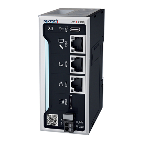
9.10 Dig/Fdig – 24V power supply for Digital I/O
and Fast Digital I/O connections
The 24V SELV power supply for the digital
I/O and fast digital I/O connections are on the
connectors ‘DIG/FDIGx’.
______________________________________
The system housing has
no provisions against wrong polarity con-
nection of the 24V I/O power supply voltage.
Observe proper polarity when connecting the 24V
I/O power supply.
______________________________________
A fuse must be installed between the 24V
SELV power supply output voltage and the
24V I/O power input voltage. The rating of the
fuse depends on the used cables and total cur-
rent.
Fuses must be certified for DC rating, Fast
Acting, and have to be UL recognized under
CCN JDXY2/8 or IEC 60127-1 certified. Sec-
ondary fuses also have to be UL or IEC certi-
fied for DC rating.
Wire gauge and wire diameter as a func-
tion of ambient temperature are derived from
the NFPA-79:2012. Insulation temperature of
wires is assumed to be 60 °C (140 °F) or 75 °C
(167 °F).
All external connected inputs and outputs
shall be separated from hazardous live by dou-
ble or reinforced insulation.
Shielded cables are mandatory for fast
digital I/O connections. Shielded cables are
recommended but not mandatory for digital
I/O connections. If shielded cables are used,
connect the shield at the system housing side to
the connector housing. Connect the other end
to a convenient metal part or leave it uncon-
nected.
For fast digital I/O signals, the cable with
the signal wire(s) should also contain the return
current path for every signal in the cable. It is
allowed that a single wire carries the return
currents for more than one signal, as long as
the current rating of the wire is not exceeded.
These measures are also recommended for the
other digital I/O.
10 Installation and Removal
______________________________________
Damage to components
may occur if power is applied during instal-
lation or removal.
•Make sure power supplies are switched
off before installation or removal of the
system housing.
•Do not apply power until the system
housing is installed.
______________________________________
Power supplies must be switched on/off
with the disconnecting device installed in the
cabinet.
The system housing may only be used as
build-in equipment in a cabinet, which means
that the end-user must provide a suitable fire
and electrical safe enclosure. The safety of any
system incorporating the system housing is the
responsibility of the assembler of the system.
The system housing may only be used in
combination with external approved power
supplies. The supply voltages 24V System,
24V Dig, and 24V Fdig for the system must be
separated at least by reinforced insulation from
all hazardous voltages according to the stand-
ard UL61010-1 third edition.
10.1 Mechanical dimensions
The dimensions of the system housing are the
following:
You can see the dimensions of the system
housings in the following views.
The dimensions given in the view exclude free
clearance space required for attached cables,
accessories and cooling requirements.
[DC]
[nominal DC current]
[nominal DC current]
NYS04.2-ST-02-LMSN-NY4073

