Bosch XDL120 User manual

XDL120 | User Manual
1 | 25
Data subj ect t o change without notice
Bosch Connected Devices and Sol utions
XDL120: Data Logger/ Data Streamer for XDK110
User Manual
XDK110: Data Logger / Data Streamer: User Manual
Document revision
1.3
Document release date
July 20th, 2018
Workbench version
3.0.0 and above
Document number
BCDS-XDK110-DataLogger-Streamer
Technical reference code(s)
Notes
Data in this document is subject to change without notice. Product
photos and pictures are for illustration purposes onlyand may differ from
the real product’s appearance.
This document is confidential and under NDA inherent with the purchase
of an XDK110.
Advance information – Subject to change without notice

XDL120 | User Manual
2 | 25
Data subj ect t o change without notice
Bosch Connected Devices and Sol utions
Table of contents
1Introduction 4
1.1 Key features of the XDL120 DataLogger/Streamer..........................................................................................................4
1.2 Components of XDL120 shipment........................................................................................................................................4
2Feature details 5
2.1 Accurate logging of sensor samples with timestamps......................................................................................................5
2.2 Global time stamp reference to sensor data.......................................................................................................................5
2.3 Online streaming of sensor samples via WLAN.................................................................................................................5
2.4 Seamless auto-save.................................................................................................................................................................5
2.5 LED indication on application state.......................................................................................................................................5
3Usage of the XDL120 7
3.1 Prerequisites ..............................................................................................................................................................................7
3.2 Overview .....................................................................................................................................................................................7
3.3 Installing the application on the XDK....................................................................................................................................7
3.4 Installing Python ........................................................................................................................................................................8
3.5 Configuration..............................................................................................................................................................................9
3.5.1 Sensor configuration 10
3.5.2 System configuration 15
3.5.3 Data transfer configuration 15
3.5.4 Network configuration 15
3.6 Data extraction & conversion .............................................................................................................................................. 16
3.6.1 Data logging 16
3.6.2 Data streaming 18
3.7 Dos and Don’ts ....................................................................................................................................................................... 20
3.8 Known Limitations.................................................................................................................................................................. 20

XDL120 | User Manual
3 | 25
Data subj ect t o change without notice
Bosch Connected Devices and Sol utions
4Data security concept 21
4.1 Introduction.............................................................................................................................................................................. 21
4.2 Stakeholders and Roles ....................................................................................................................................................... 22
4.2.1 XDL user 22
4.2.2 Bosch Connected Devices and Solutions 22
4.3 Physical and Environmental Security................................................................................................................................ 22
4.3.1 Use Case Scenario 1 (Deployment at private area) 22
4.3.2 Use Case Scenario 2 (Deployment in industry) 22
4.3.3 Use Case Scenario 3 (Deployment in public area) 22
4.4 Asset Management / Media Handling............................................................................................................................... 22
4.5 Access control......................................................................................................................................................................... 23
4.5.1 Media Handling 23
4.5.2 Access to Networks 24
4.6 Encryption ................................................................................................................................................................................ 24
4.7 Termination of service........................................................................................................................................................... 24
5Known Issues 24
6References 24

XDL120 | User Manual
4 | 25
Data subj ect t o change without notice
Bosch Connected Devices and Sol utions
1Introduction
The Data Logger / Streamer application for Cross-Domain Development Kit XDK110 is intended to extract raw data from
the XDK with the highest performance achievable with the build-in sensors, giving the user the ability to acquire reliable,
highly accurate data for further analysis. The data are stored locally on the SD card within the device. Alternatively, the data
can also be sent to a network computer via WLAN.
1.1 Key features of the XDL120 DataLogger/ Streamer
Easy data acquisition from on-board sensors of XDK (except acoustic noise) with high data rates
Customizable: Sensor selection and configuration via xml file, no programming needed
Saves data locally on SD card (logging mode)
Transmits data continuously via WLAN to a UDP socket (streaming mode) (Enterprise WPA2 option available)
Auto save feature with configurable saving frequency
MessagePack format for integration in third-party applications
Time-equidistant sampling with global time synchronization support with SNTP over WLAN
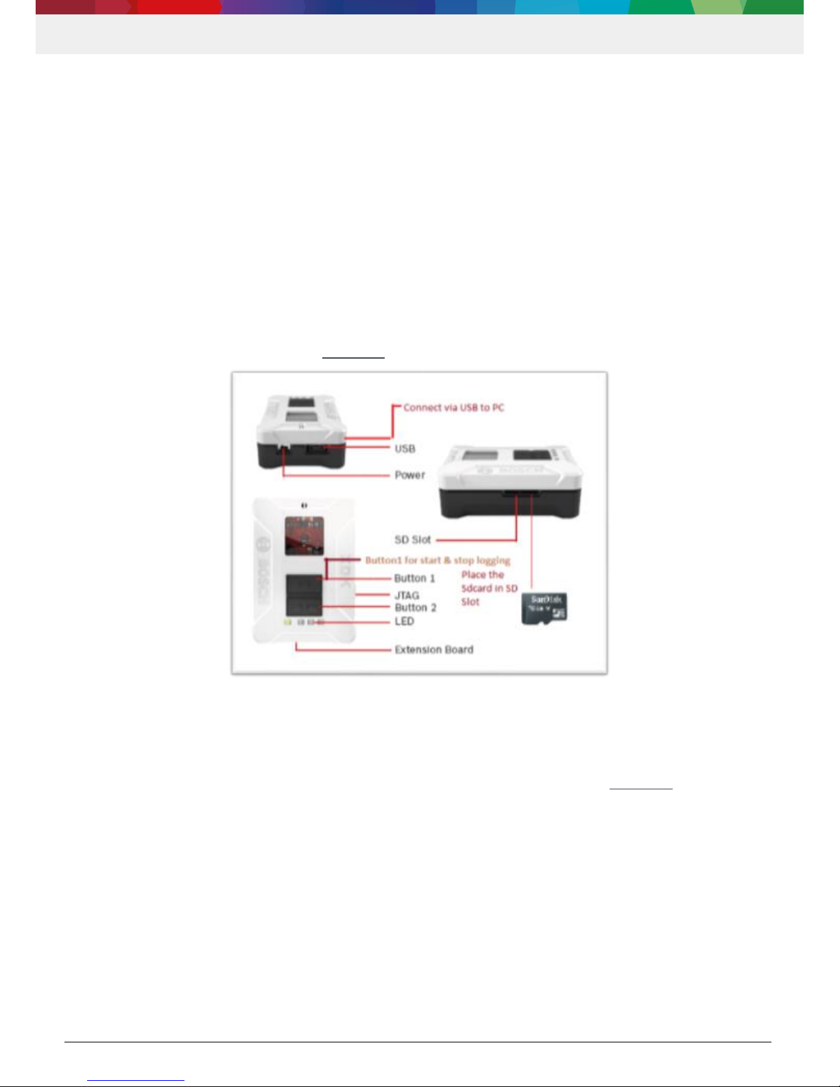
Simply pressing a button starts and stops data logging/streaming
1.2 Components of XDL120 shipment
The following components are part of the XDL120:
Binary files (full version):
oXDL120_Rev1.bin : for XDK with bootloader <v1.0
oXDL120_Rev2.bin : for XDK with bootloader ≥v1.0
Binary files (trial version):
oXDL120_trial_Rev1.bin : for XDK with bootloader <v1.0
oXDL120_trial_Rev2.bin : for XDK with bootloader ≥v1.0
Datalogger.exe (alternative: datalogger.py python script for systems with python3 environment available)
config.XML file
wlan.TXT file
XDL120_tolerance_calculation.xls
EULA / Licence text (PDF)
User manual (this document)
NOTE
If you are using the trial version of the XDL120, the features and usage as described in this manual are identical to the
full version with the exception of the logging time.
The trial version only allows for logging of up to 30 minutes per log.

XDL120 | User Manual
5 | 25
Data subj ect t o change without notice
Bosch Connected Devices and Sol utions
2Feature details
2.1 Accurate logging of sensor samples with timestamps
The XDL120 allows logging with high data rates for all on board sensors except the acoustic noise sensor without loss of
data, when individual sensors are configured. Data is homogeneously timestamped with millisecond resolution based on
the FreeRTOS system time. Table 1 provides a quick overview on the maximum sample rates per sensor. Please be aware
that those rates only apply if a single sensor is configured at a time for logging. For multiple sensors, the data rate for the
single sensors must be reduced.
The value described in the table refer to maximum values achieved in ideal conditions. In real applications, some data
might be lost e.g. due to noise on the sensor bus induced by increased temperature, or other factors. In our tests, the data
loss exhibited under real life testing conditions were typically in range of <0.5% of the maximum values setting.
If data from more than one sensor needs to be logged, it is recommended to reduce the data rate for the individual sensors
to minimize data loss. The file XDL120_tolerance_calculation.xls delivered with the XDL120 can help estimate typical data
loss when logging several sensors at once.
Table 1: Maximum raw data output of XDK sensors
Sensor
Data rate
BMI 160 – Gyroscope part
3200 Hz
BMI 160 – Acceleration part
1600 Hz
BMM150 – Magnetic field
30 Hz
BMA280 – Acceleration
1000 Hz (corresponds to bandwidth 500 Hz)
BME280 – Temperature, Humidity, Pressure
25 Hz
BMG160 – Gyroscope
1000 Hz (corresponds to bandwidth 500 Hz)
MAX44009 – Light
25 Hz
For further details on sensor parameters, please refer to section 3.5.1
2.2 Global time stamp reference to sensor data
The application allows you to configure an SNTP time server (see Configuration for details) to obtain a global time stamp
for your measurement data. The Synchronization is done once on power-on of the XDK. The device will (re-)try to establish
a connection up to four times (see Table 2: LED pattern of the XDL120 for details). This feature requires WLAN access.
Please make sure to select a time server that is reachable from your local network.
2.3 Online streaming of sensor samples via WLAN
XDL120 allows to stream sensor data live during logging using WLAN, with a focus on high data-rates (see Configuration
for details). The data will be sent via UDP to a host within the same network. Due to the nature of the protocol and the RF
conditions in the target application, this method cannot guarantee package delivery (packet loss may be possible). Please
analyze the time stamp provided to identify lost packages.
2.4 Seamless auto-save
The seamless Auto-save is one of the key feature of the Data Logger / Streamer application. The user can configure the
time interval in which to store the logs in separate files when the Data Logger / Streamer application is configured to log
data to the SD Card. Based on the time interval configured in the config.xml file, a new log file is created for every time
interval. This feature will not interrupt logging and at the same time it saves data. The user can configure the auto-save
time interval from 1 min to 24 hours. Given a configuration of 2 min, a new log file will be created every two minutes.
2.5 LED indication on application state
Four LEDs are available on the XDK and each LED except the green LED indicates a specific state of the application. The
possible LED patterns and their causes are listed in Table 2.

XDL120 | User Manual
6 | 25
Data subj ect t o change without notice
Bosch Connected Devices and Sol utions
Table 2: LED pattern of the XDL120
State Name
LED State
Condition for appearance / State
description
Yellow
Orange
Red
Data logger /streamer
not ready /
No SNTP time stamp
acquired
OFF
ON
ON
Data logger / streamer initialization is not
completed.
Data logger /
streamer ready
OFF
OFF
OFF
Data logger / streamer initialization is
completed and ready to log data.
Logging
ON
OFF
OFF
When button 1 pressed, logging starts.
SNTP error
ON -
If logging
state
OFF-
If not in
logging state
Blink -
If a data loss
occurred
OFF -
If no data
loss occurred
ON
When the SNTP server did not send a
response (OR)
The application is not able to receive data
from server (OR)
WLAN connection could not be established.
Data Loss
ON
Blink
depends on
the
frequency of
the data loss
OFF-
No SNTP error
occurred
ON-
If a SNTP
error occurred
Indicates data loss due to environmental
conditions or sub-optimal sensor
configuration.
Fatal error
Blink for
every 1sec
Blink for
every 1sec
Blink for every
1sec
When no SD card is inserted. (OR)
Due to an invalid configuration file on the SD
card. (OR)
Configuration file contains invalid
configuration parameters. (OR)
WLAN is enabled and no WLAN could be
established. (OR)
All sensors are disabled in the configuration
file.

XDL120 | User Manual
7 | 25
Data subj ect t o change without notice
Bosch Connected Devices and Sol utions
3Usage of the XDL120
3.1 Prerequisites
The following items are needed to use the XDL120:
microSD card for configuration and data storage
microSD card reader to write configuration and to retrieve sensor data
XDK device with micro USB cable
XDK workbench installed on computer
Microsoft Windows 7 or greater or Python >= 3.4 with dependencies installed on computer as listed below
3.2 Overview
Figure 1: User interface external view of XDK shows the user interface of the XDK110 device. For more details, please
refer to the XDK documentation available at www.xdk.io.
3.3 Installing the application on the XDK
To use the XDK120, the respective binary file has to be installed (“flashed”) onto the XDK device. This is done via the XDK
workbench. Information on how to install the XDK workbench is available on the XDK website (www.xdk.io). It is
recommended to have a look at the XDK First Steps Guide to get familiar with the workbench. After Installation, follow the
description below to flash the binary:
Run the XDK-Workbench.exe application, by default the welcome screen will appear on the opening screen of the
XDK-Workbench.
Figure 1: User interface external view of XDK

XDL120 | User Manual
8 | 25
Data subj ect t o change without notice
Bosch Connected Devices and Sol utions
Figure 2: XDK Workbench welcome screen
Click on Click & Go tab, then the default operating view for implementing XDK projects will appear.
Please make sure that the connected XDK is turned on and displayed in the XDK Devices view.
oThe name of the XDK device can be changed by right-clicking on the device icon
Drag and drop the correct binary for your bootloader version (XDL120_Rev1.bin or _Rev2.bin) onto the XDK in the XDK
Devices view, e.g. from the explorer window.
oThe binary will now be flashed to the XDK
After the binary file was flashed, the XDK will automatically start the flashed application. The XDL120 is now ready to log
and stream sensor data.
3.4 Installing Python
If you cannot use the datalogger.exe to convert the logging files (see section 3.6), Python needs to be installed to run the
datalogger.py script. If you can use the EXE file, you can skip this chapter.
To install and setup python:
Download python version 3.x or higher here: https://www.python.org/downloads/
oIf working under windows it is recommended to add the Python installation to the system's path.
Instructions can be found here: http://stackoverflow.com/questions/6318156/adding-python-path-on-
windows-7
oNote: If this is not possible, the python script can still be used. However, python script must be called from
its installation directory
Download py-serial here: https://pypi.python.org/pypi/pyserial (File: pyserial-3.3-py2.py3-none-any.whl (md5)).
Install py-serial with the following command: python -m pip install pyserial-3.3-py2.py3-none-any.whl.
Figure 3: XDK data logger debug/flash & reboot options in workbench

XDL120 | User Manual
9 | 25
Data subj ect t o change without notice
Bosch Connected Devices and Sol utions
Download and install the pandas dependencies packages mentioned in the page: https://pypi.python.org/pypi/pandas
ohttps://pypi.python.org/pypi/numpy
ohttps://pypi.python.org/pypi/pytz
ohttps://pypi.python.org/pypi/python-dateutil
Install the pandas with following command(v0.21.0) : python -m pip install pandas mentioned in the page
http://pandas.pydata.org/
Download and install the dependencies packages:
oFor xlsx:
https://pypi.python.org/pypi/et_xmlfile
https://pypi.python.org/pypi/jdcal
https://pypi.python.org/pypi/openpyxl
oFor HDF:
https://pypi.python.org/pypi/numexpr
https://www.lfd.uci.edu/~gohlke/pythonlibs/#pytables
oFor parquet
https://pypi.python.org/pypi/llvmlite
https://www.lfd.uci.edu/~gohlke/pythonlibs/#pytables
https://pypi.python.org/pypi/Cython/
https://pypi.python.org/pypi/fastparquet
Python is now setup to convert the logged files to required output format.
An alternative method is installing python and upgrading required package via single utility called “Anaconda”
https://www.anaconda.com/download/
NOTICE:
The following script files included in the XDL120 shipment are also needed for the conversion and must be available in
the same folder as the datalogger.py: convert.py, custom_binary_parser.py, custom_dataframe_generator.py,
msgpack_binaryparser.py, outputformater.py, xdk_wifi_datalogger.py.
3.5 Configuration
Once the XDL120 binary is flashed, the XDL120 needs to be configured by modifying the wlan.txt and config.xml files.
Those files need to be placed on the microSD card which is inserted in the XDK. The wlan.txt file is used to store the
network configuration (WLAN credentials), as described in section 3.5.4. The content of the config.xml file is listed as
follows:
<datalogger>
<sensors>
#Individual sensor configurations
</sensors>
<system>
#system configurations
</system>
<datatransfer>
#Datatransfer configurations
</datatransfer>
</datalogger>

XDL120 | User Manual
10 | 25
Data subj ect t o change without notice
Bosch Connected Devices and Sol utions
Three different nodes in the config.xml file are available for user configuration:
Sensors: Configuration for all the sensors
System: Configuration such as auto save and data format
Data Transfer: Configuration for enabling/disabling WLAN and configuring the time server
Once the application is started and can read the configurations properly, data logging can be started and stopped by simply
pressing button one. When data logging is started it needs to be stopped and the XDK turned off before the SD card should
be removed. This is necessary because the XDL120 does not integrate auto detection regarding a removed SD card and
will show unintended behavior. Please note that errors are displayed via the onboard LEDs of the XDK. For information
about them please refer to section 2.5 where these are explained in detail.
CAUTION:
Do not alter the name or sequence of the tags.
Do not remove any of the tags in the XML file.
Do not add any in-appropriate value OR out of range value to the corresponding tag.
“Enabled” tag should contain the value as either true or false.
3.5.1 Sensor configuration
The XDK provides an accelerometer (Bosch Sensortec BMA280), gyroscope (Bosch Sensortec BMG160), magnetometer
(Bosch Sensortec BMM150), inertial measurement unit (Bosch Sensortec BMI160), a combined temperature, humidity and
pressure sensor (Bosch Sensortec BME280) and a light sensor (Maxim MAX44009). These sensors are configured in the
config.xml file. Details on the sensors can be found in the “XDK General Information” guide (www.xdk.io). Each sensor has
a specific set of parameters that can be configured to the need of the use case. The XML configuration file contains already
all sensor configuration settings. Each sensor can be independently enabled or disabled by selecting the enable tag.
<enabled>true</enabled> to enable the sensor
<enabled>false</enabled> to disable the sensor
The following excerpt shows a sample of the configurable XDK sensors of the config.xml file with only the BMA280
acceleration sensor enabled.
<sensors>
<bmi160>
<enabled>true</enabled>
<gyro_odr>0x0c</gyro_odr>
<gyro_bw>0x00</gyro_bw>
<gyro_range>0x04</gyro_range>
<accel_odr>0x0c</accel_odr>
<accel_bw>0x00</accel_bw>
<accel_range>0x03</accel_range>
</bmi160>
<bmm150>
<enabled>true</enabled>
<odr>0x07</odr>
<rep_xy>0x03</rep_xy>
<rep_z>0x03</rep_z>
</bmm150>
<bma280>
<enabled>true</enabled>

XDL120 | User Manual
11 | 25
Data subj ect t o change without notice
Bosch Connected Devices and Sol utions
<accel_bw>0x06</accel_bw>
<accel_range>0x03</accel_range>
</bma280>
<bme280>
<enabled>true</enabled>
<odr>0xf9</odr>
<power_mode>0x03</power_mode>
<standby_dur>0x04</standby_dur>
<filter_coeff>0x00</filter_coeff>
<oversamp_temperature>0x04 </oversamp_temperature>
<oversamp_pressure>0x04</oversamp_pressure>
<oversamp_humidity>0x04</oversamp_humidity>
</bme280>
<bmg160>
<enabled>true</enabled>
<gyro_bw>0x01</gyro_bw>
<gyro_range>0x02</gyro_range>
</bmg160>
<max44009>
<enabled>true</enabled>
<integration_time>0x00</integration_time>
<odr>0xf9</odr>
<continuous_mode>0x00</continuous_mode>
<manual_config>0x00</manual_config>
<cdr>0x00</cdr>
</max44009>
<marker>
<enabled>true</enabled>
</marker>
</sensors>
To configure the sensors to suit a desired behavior, change the parameters according to it. For example, to set the Gyro
Bandwidth of the BMI160 change the value in <gyro_bw>(value)</gyro_bw> to the desired possible value for the
bandwidth listed in the table of the configuration parameters.
<sensors>
<bmi160>
<enabled>true</enabled> Enabled
<gyro_odr>0x0a</gyro_odr>
<gyro_bw>0x03</gyro_bw> Changed to 0x03 = ±250°/s
<gyro_range>0x04</gyro_range>
<accel_odr>0x0a</accel_odr>
<accel_bw>0x02</accel_bw>
<accel_range>0x03</accel_range>
</bmi160>
NOTICE
The <marker> section of the config.xml is needed for internal use and must be enabled (true) for the XDL120 to work
correctly. Please do not change this configuration.
The full list of all parameters is summarized in Table 3 to Table 8. For more details, please refer to the data sheets of the
respective sensors.

XDL120 | User Manual
12 | 25
Data subj ect t o change without notice
Bosch Connected Devices and Sol utions
Table 3: Sensor parameters for BMI160 (Inertial Measurement Unit)
Sensor
parameter
Tag in XML
file
Possible setting
XML hex
value
Notes
Gyroscope
Output Data
Rate
<gyro_odr>
25 Hz
50 Hz
100 Hz
200 Hz
400 Hz
800 Hz
1600 Hz
3200 Hz
0x06
0x07
0x08
0x09
0x0A
0x0B
0x0C
0x0D
Normal mode is selected for Gyroscope operations.
Low energy modes are currently not supported.
Note: ODR values below 25 Hz are not allowed and
will produce an error
Gyroscope
Bandwidth
<gyro_bw>
OSR4 MODE
OSR2_MODE
NORMAL_MODE
CIC_MODE
0x00
0x01
0x02
0x03
Bandwidth parameter is used to set the response
time of the Gyroscope.
NORMAL MODE- Gyroscope data samples at
equidistant points in time.
OSR2 MODE- Data oversampling with a rate of 2.
OSR4 MODE- Data oversampling with a rate of 4.
Note: Configurations without Bandwidth are illegal
and will result in errors.
Gyroscope
Range
<gyro_range>
2000 degree/s
1000 degree/s
500 degree/s
250 degree/s
125 degree/s
0x00
0x01
0x02
0x03
0x04
Accelerometer
Output Data
Rate
<accel_odr>
0.78 Hz
1.56 Hz
3.12 Hz
6.25 Hz
12.5 Hz
25 Hz
50 Hz
100 Hz
200 Hz
400 Hz
800 Hz
1600 Hz
0x01
0x02
0x03
0x04
0x05
0x06
0x07
0x08
0x09
0x0A
0x0B
0x0C
Normal mode is selected for acceleration operation.
Note: The product of the bandwidth parameter and
Output data rate parameter must not exceed 1600.
Accelerometer
Bandwidth
<accel_bw>
OSR4_AVG1
OSR2_AVG2
NORMAL_AVG4
CIC_AVG8
RES_AVG2
RES_AVG4
RES_AVG8
RES_AVG16
RES_AVG32
RES_AVG64
RES_AVG128
0x00
0x01
0x02
0x03
0x04
0x05
0x06
0x07
0x08
0x09
0x0A
The bandwidth parameter is used to set the
response time of the acceleration sensor.
Possible ODR for OSR2, OSR4, NORMAL & CIC
from 12.5 Hz to 1600 Hz.
ODR for AVG2 to AVG128 from 0.78 Hz to
decreasing power of 200.
Note: Please verify the accelerometer bandwidth
before setting the output data rate
Accelerometer
Range
<accel_range>
RANGE_2G
RANGE_4G
8G
RANGE_16G
0x03
0x05
0x08
0x0C
Table 4: Sensor parameters for BMM150
Sensor
parameter
Tag in XML
file
Possible setting
XML hex
value
Notes
Output Data
Rate
<odr>
10 Hz (standard)
02 Hz
06 Hz
0x00
0x01
0x02

XDL120 | User Manual
13 | 25
Data subj ect t o change without notice
Bosch Connected Devices and Sol utions
08 Hz
15 Hz
20 Hz
25 Hz
30 Hz
0x03
0x04
0x05
0x06
0x07
Repetitions on
X and Y axes
<rep_xy>
rep_xy
repetitions X and Y
nXY = 1 + 2 * repXY
Repetitions are the number of measured
points to generate one sample, the more
repetitions the higher the measurement
accuracy.
Repetitions on
the Z axis
<rep_z>
Repetitions Z
nZ = 1 + repZ
Related to Z-Axis
Table 5: Sensor parameters for BMA280
Sensor
parameter
Tag in XML
file
Possible
setting
XML hex
value
Notes
Bandwidth
<accel_bw>
7.81 Hz
15.63 Hz
31.25 Hz
62.50 Hz
125 Hz
250 Hz
500 Hz
0x00
0x01
0x02
0x03
0x04
0x05
0x06
Bandwidth parameter is used to set the output data
rate of the acceleration sensor.
Range
<accel_range>
2G
4G
8G
16G
0x00
0x01
0x02
0x03
Table 6: Sensor parameters for BME280
Sensor
parameter
Tag in XML file
Possible setting
XML
hex
value
Notes
Output Data
Rate
<odr>
0.1 Hz,
0.2 Hz,
....,
25 Hz
0x00,
0x01,
….
0xf9
Output data rate setting resolution
of 0.1 Hz.
Power Mode
<power_mode>
SLEEP_MODE
FORCED_MODE
NORMAL_MODE
0x00
0x01
0x03
The environmental sensor can
operate in three different modes:
sleep, forced and normal.
Standby
Duration
<standby_dur>
1MS
63MS
125MS
250MS
500MS
1000MS
2000MS
4000MS
0x00
0x01
0x02
0x03
0x04
0x05
0x06
0x07
The standby duration is the amount
of time the sensor is in idle state.
The possible standbytimes range
from 1ms to 4 s.
Note: The measurement rate
in normal mode depends on
the measurement time and
the standby time
Filter
Coefficient
<filter_coeff>
COEFF_OFF
COEFF_2
COEFF_4
COEFF_8
COEFF_16
0x00
0x01
0x02
0x03
0x04
Controls the time constant of the
filter.
The response time depends on the
filter coefficient selected.
Note: The number of samples will
increase if the

XDL120 | User Manual
14 | 25
Data subj ect t o change without notice
Bosch Connected Devices and Sol utions
response time is longer which is
dependent on filter coefficient
selection
Over-
Sampling:
Temperature/
Pressure/
Humidity
<oversamp_temperature>
<oversamp_pressure>
<oversamp_humidity>
Skipped
1X
2X
4X
8X
16X
0x00
0x01
0x02
0x03
0x04
0x05
Parameter to configure how often
the sensor values during a
sampling period are sampled from
the sensor
Oversampling setting is used to
reduce noise
Table 7: Sensor parameters for BMG160
Sensor
parameter
Tag in XML
file
Possible setting
XML hex
value
Notes
Bandwidth
<gyro_bw>
500 Hz
230 Hz
116 Hz
47 Hz
23 Hz
12 Hz
64 Hz
32 Hz
0x00
0x01
0x02
0x03
0x04
0x05
0x06
0x07
Range
<gyro_range>
RANGE_2000
RANGE_1000
RANGE_500
RANGE_250
RANGE_125
0x00
0x01
0x02
0x03
0x04
Table 8. Sensor parameters for MAX44009
Sensor
parameter
Tag in XML file
Possible setting
XML hex
value
Notes
Integration
Time
<integration_time>
800 ms
400MS
200MS
100MS
50MS
25MS
12.5ms
6.25ms
0x00
0x01
0x02
0x03
0x04
0x05
0x06
0x07
The integration time is a time window
during which a pulse is measured.
800ms - This is a preferred for
boosting low-light sensitivity.
100ms - for high brightness.
6.25ms-50ms for manual mode only.
Note: In automatic mode (MANUAL
= 0), integration
time is automatically selected by the
on-chip algorithm to
be either
100ms/200ms/400ms/800ms
Output Data
Rate
<odr>
0.1 Hz,
0.2 Hz,
....,
25 Hz
0x00
0x01
….
0xf9
Output data rate setting with
resolution of 0.1 Hz.
Note: Continuous mode is
independent of the manual mode
setting
Continuous
Mode
<continuous_mode>
DISABLE
ENABLE
0x01
0x00
Select the continuous mode
configuration.
Manual
Configuration
DISABLE
ENABLE
0x01
0x00
currently unused, recommended to
keep DISABLE
Current
Devision Ratio
<cdr>
NORMAL_BRIGHTNESS
HIGH_BRIGHTNESS
0x00
0x01
Division ratio used to divide the
photo diode current.

XDL120 | User Manual
15 | 25
Data subj ect t o change without notice
Bosch Connected Devices and Sol utions
3.5.2 System configuration
The system part of the config.xml determines the behavior of the data format and the autosave function.
<system>
<msgpack>
<msgpack_enabled>false</msgpack_enabled>
</msgpack>
<autosave>
<enabled>true</enabled>
<save_time>0x0001</save_time>
</autosave>
</system>
Data format:
The XDL120 offers the possibility to either store / stream files in binary or in MessagePack format. MessagePack is an
efficient binary serialization format. It lets you exchange data among multiple languages like JSON and is aimed for users
who want to integrate data from XDL120 directly into a third-party application via WLAN streaming. On the downside, it
does not allow the maximum data rate in all sensor settings and therefore increases the risk for data loss during logging.
Therefore, for the highest data rate it is recommended to disable the <msgpack> tag and use the binary format.
Autosave
By enabling the autosave functionality, the Data Logger / Streamer generates new log files within the set interval, which
can be set using the <save_time> tag. The value is declared in minutes using hex format. (One minute, for example,
represents the hex value 0x01). The <save_time> can be configured arbitrary from 1 min to 24 h. If autosave is disabled,
only one binary will be created containing the complete measured sensor values. Please note that this feature is only
available if the XDL120 is configured for data logging, not for streaming.
3.5.3 Data transfer configuration
The user can select the data transfer medium (microSD card or UDP via WLAN). By default, the data transfer medium is
the microSD card. The server IP address 6666 is predefined but can be changed if necessary.
<datatransfer>
<wifi>
<sntp_globalAddress>YourSNTPServerURL</sntp_globalAddress>
<enabled>false</enabled>
<wifi_serverPort>6666</wifi_serverPort>
<wifi_serverIP>YourDataLoggerServerIP</wifi_serverIP>
</wifi>
</datatransfer>
</datalogger>
Additionally, the configuration includes the SNTP server address, which is used to acquire an absolute time stamp. This
feature can be used independently from the mode of data transfer, but requires a one-time connection to the server via
WLAN at the startup of the application. See section 3.5.4 for WLAN configuration.
3.5.4 Network configuration
In order to obtain a global time stamp, or to stream sensor data via WLAN, a network configuration must be saved on the
XDK. This is done by editing the wlan.txt file shipped with the XDL120.
WLAN_ENTERPRISE=false
If "true" then Enterprise WPA connection and if "false" then Personal WPA
connection will be established
WLAN_SSID=YourWLANSSID
Provide your WPA SSID name
WLAN_USERNAME=YourWLANUsername
Provide your WPA username (unused if NETWORK_ENTERPRISE is
false)
WLAN_PASSWORD=YourWLANPassword
Provide your WPA password

XDL120 | User Manual
16 | 25
Data subj ect t o change without notice
Bosch Connected Devices and Sol utions
WLAN_STATIC_IP=false
If "true" then static IP will be assigned and if "false" then DHCP
WLAN_IP_ADDR=128.0.0.1
Provide your static IPv4 IP address (unused if NETWORK_STATIC_IP is
false)
WLAN_GW_ADDR=128.0.0.1
Provide your IPv4 gateway address (unused if NETWORK_STATIC_IP is
false)
WLAN_DNS_ADDR=128.0.0.1
Provide your IPv4 DNS address (unused if NETWORK_STATIC_IP is
false)
WLAN_MASK=128.0.0.1
Provide your IPv4 mask (unused if NETWORK_STATIC_IP is false)
WLAN_SERVICEPACK_UPDATE=false
If "true" then the service pack of the WLAN chip is updated and a dummy
certificate is flashed to be used for Enterprise WPA2 connection. Custom
certificates are not yet supported
The wlan.txt will be read by the XDK during startup and the network configuration will be copied into the internal flash.
Afterwards, the network configuration does not need to be the SD card for logging. This ensures that the network
credentials can be kept private even if the XDK is operated with WLAN connection. For more information, please refer to
section 4Data security concept.
3.6 Data extraction & conversion
As mentioned, the XDL120 allows the user to either log data onto a microSD card, or to stream data via WLAN to a UDP
port. The following sections describe how to use these features.
3.6.1 Data logging
The XDL120 stores the sensor data in binary format on the SD-card in sequence with the specified save time. In order to
convert this binary files to human readable format, a converter is provided as an EXE file or as a python script to parse the
sensor data. Once the XDL120 binary is flashed on to the XDK take the following steps:
If you want to synchronize the timestamp via a global timeserver, insert a microSD card with the WLAN credentials into
the XDK and switch the device on. The credentials will then be read and transferred to the flash memory. It is
recommended to replace the microSD card before logging and not to store the credentials on the same card as the
config.xml file and the logfiles. See section 4.5.2 for details.
Insert the microSD card with config.xml file into the XDK
Press XDK button-1 to start logging.
oBefore start logging LED indication with “Data Ready” pattern is displayed.
oDuring the Logging Yellow Led will be ON.
oLogging parameters can be set using the config.xml file.
Wait for the required time to keep the data logger active and press again button 1 to stop logging.
Once data logging is done switch the XDK device OFF and remove the microSD card from the device. (push the
memory card for easy removal)
Put this microSD card into a card reader connected to a computer. Copy the binary files produced from the memory card
to a local drive.
To convert the binary files into the designated output format, use either the datalogger.exe or datalogger.py file included
in the XDL120 shipment, as shown below. The files are called using the console application (e.g. command prompt on
Windows).
datalogger.exe convert [-h] [-f {'pandas|csv|hdf|xlsx|json|msgpack|parquet'}] [-o
[OUTPUT_FOLDER [OUTPUT_FOLDER ...]]] [-r [RECURSIVE_FOLDER [RECURSIVE_FOLDER ...]]] [-p
{'custom|msgpack'}] [-c OFFSET] [files [files ...]]
or
python datalogger.py convert [-h] [-f {'pandas|csv|hdf|xlsx|json|msgpack|parquet'}] [-o
[OUTPUT_FOLDER [OUTPUT_FOLDER ...]]] [-r [RECURSIVE_FOLDER [RECURSIVE_FOLDER ...]]] [-p
{'custom|msgpack'}] [-c OFFSET] [files [files ...]]

XDL120 | User Manual
17 | 25
Data subj ect t o change without notice
Bosch Connected Devices and Sol utions
Positional arguments:
files
List of files to convert. Multiple files can be
separated via spaces.
Optional arguments:
-h, --help
show this help message and exit
-f {pandas,csv,hdf,xlsx,json,msgpack,parquet}, --format
{pandas,csv,hdf,xlsx,json,msgpack,parquet}
List of available format to convert the bin file.
Default is csv.
-o [OUTPUT_FOLDER [OUTPUT_FOLDER ...]], --output_folder
[OUTPUT_FOLDER [OUTPUT_FOLDER ...]]
output folder path
-r [RECURSIVE_FOLDER [RECURSIVE_FOLDER ...]], --
recursive_folder [RECURSIVE_FOLDER
[RECURSIVE_FOLDER ...]]
recursive folder path
-p {'custom|msgpack'}, --parser {'custom|msgpack'}
list of available parser types
-c OFFSET,--temperature_correction OFFSET
Temperature correction factor. Default is -2.1K.
See section 3.8 for details.
After running the conversion, a log file (e.g. .csv) will be created for each sensor enabled. The stat.csv file is holding statistics
on hardware-caused data loss. This happens when high sensor bandwidths are configured and then overlap with the system's
internal processing time. The file manual.csv is holding the template row names, which are present in all .csv files where
sensor values are stored. The following names for the rows are stored in manual.csv as templates:
Sensor_ID: The sensor id is placed at the start of the preamble. Each sensor is defined with specific ID numbers. The
sensor identification numbers are defined as follows bmi-1 (BMI160), bmm-2 (BMM150), manual-3, light-4
(MAX44009), bme-5 (BME280), bma-6 (BMA280) and bmg-7 (BMG160).
Sequence_Number (sqn): Whenever raw data is obtained the sequence number is incremented for each sensor. Data
loss can be determined using the sequence number.
Data_Length: Data length is the length of the raw sensor data. It is a constant for the chosen sensor.
MCU_TimeStamp: This is the time stamp provided by the MCU of the XDK.
Real_TimeStamp: This is the timestamp synchronized with a SNTP server, currently it set to the initial timestamp of
NTP at 1970 because WLAN is disabled, when configuring data logging
Other parameters for a particular sensor are the respective sensor value descriptions as shown in Figure 4 .
A complete list of the different row parameters for the different sensors is displayed in Table 1Table 9.
Figure 4: BMA280 detail view: .csv file

XDL120 | User Manual
18 | 25
Data subj ect t o change without notice
Bosch Connected Devices and Sol utions
Table 9: Parameter labels in output file
Sensor
Number
Sensor Name
Output parameters from
Sensor
Output parameters provided
from CSV file
1
BMI160 - Inertial Measurement
Unit
Accel data -
accel_x, accel_y, accel_z
Gyro data -
gyro_x, gyro_y, gyro_z
sensor_id*, sqn**,
mcu_timestamp,
data_length, bmi_accel_x,
bmi_accel_y, bmi_accel_z,
bmi_gyro_x,bmi_gyro_y,
bmi_gyro_z,
bmi_timestamp,
RealTimestamp
2
BMM150 - Magnetometer
Magnitude data -
bmm_x, bmm_y, bmm_z
and the resistance
sensor_id, sqn,
mcu_timestamp,
dataLength, bmm_mag_x,
bmm_mag_y, bmm_mag_z,
bmm_resistance,
RealTimestamp
3
BMA280 - Accelerometer
Accel data x,y & z along with
temperature
sensor_id, sqn,
mcu_timestamp,
data_length ,bma_accel_x,
bma_accel_y
,bma_accel_z,bma_temp,
RealTimestamp
4
BME280 - Environmental Sensor
Temperature, Pressure,
Humidity
sensor_id, sqn,
mcu_timestamp,
dataLength, temperature,
humidity, pressure,
RealTimestamp
5
BMG160 - Gyroscope
Gyro Data x,y & z
sensor_id, sqn,
mcu_timestamp,
dataLength, bmg_gyro_x,
bmg_gyro_y, bmg_gyro_z,
RealTimestamp
6
MAX44009 - Light Sensor
Light strength
sensor_id, sqn,
mcu_timestamp,
dataLength, lightStrength,
RealTimestamp
Furthermore, the stat.csv offers statistics on how much sensor data was lost during the processing time. The following
parameters are used as row descriptions:
Lost_count: The total amount of times data was lost is stored in stat.csv file. For each sensor, loss count is calculated
and updated in the respective field. A field for the bma280 is for example lostBmaDrdy. The data loss is also shown
during the run time over the orange LED.
QueueFull: Queuefull indicates, that the queue temporarily holding buffer for the sensor data is full and needs further
processing, such as streaming it via UDP or logging it to the SD card. A full queue results in that no further sensor data
can be stored until it is emptied.
3.6.2 Data streaming
To enable data streaming, the following steps need to be taken:
Make sure the WLAN settings (SSID/ Password) are stored on the XDK. Please refer to section 4.5.2 to make sure this
is done without unnecessary exposure of the credentials.
Set the <enable> tag within the <wifi> tag within the <datatransfer> tag in the XML configuration to true and
enter the relevant parameters in the wlan.txt (see section 3.5). In addition, set sntp_globalAddress in the config.xml file
to enable SNTP time stamp.

XDL120 | User Manual
19 | 25
Data subj ect t o change without notice
Bosch Connected Devices and Sol utions
Start the datalogger server on the UDP port configured using the datalogger.exe using the command prompt on
Windows. Alternatively, the Python script datalogger.py can be used to start the server (please refer to section 3.4 for
the python installation). The arguments of the server call are as follows:
datalogger.exe server [-h] [-i SERVER_IP] [-p SERVER_PORT] [-t TIMEOUT] [-f
{pandas,csv,hdf,xlsx,json,msgpack,parquet}] [-o OUTPUT] [-c OFFSET]
or
python datalogger.py server [-h] [-i SERVER_IP] [-p SERVER_PORT] [-t TIMEOUT] [-f
{pandas,csv,hdf,xlsx,json,msgpack,parquet}] [-o OUTPUT] [-c OFFSET]
Optional arguments:
-h, --help
show this help message and exit
-i SERVER_IP, --ip SERVER_IP
The IP address of the interface connected to the
network the XDK is on. IPv4 only. Default is 0.0.0.0
(listen on all interfaces).
-p SERVER_PORT, --port SERVER_PORT
The port the datalogger should listen on. Defaults
to 6666.
-t TIMEOUT, --timeout TIMEOUT
Timeout in seconds to wait for a connection.
Default is 120s.
-f {pandas,csv,hdf,xlsx,json,msgpack,parquet}, --format
{pandas,csv,hdf,xlsx,json,msgpack,parquet}
List of available format to convert the bin file.
Default is csv.
-o OUTPUT, --output OUTPUT
Target file name. Default is 'WLAN_Data_Log'
--overwrite
Overwrite bin file and all files produced conversion
if they exist. Default is to prompt if bin file exist.
Will not check if files exist before conversion.
-c OFFSET,--temperature_correction OFFSET
Temperature correction factor. Default is -2.1K.
See section 3.8 for details.
Press button 1 on XDK within the configured timeout interval to start logging.
Data will now be saved as .bin file on computer.
Press button 1 again to stop logging. When stopped, the server will convert the .bin file to defined format: .csv (default),
pandas, hdf xlsx, json, msgpack, or parquet.
For explanation on the file content, see Table 9.
The XDL120 also supports to stream data via Enterprise WPA2 WLAN network for increased security. To enable WPA2
Enterprise connection and communication, make sure that in the wlan.txt file WLAN_ENTERPRISE and
WLAN_SERVICEPACK_UPDATE are set to true apart from providing the right credentials for WLAN_SSID,
WLAN_USERNAME and WLAN_PASSWORD. Please be aware that making the WLAN_SERVICEPACK_UPDATE as true is a
pre-requisite for any bare-metal XDK to support Enterprise WPA2 connection and leaving this as true will update the
WiFi chip every single time it boots. Therefore, it is advised that the user should set WLAN_SERVICEPACK_UPDATE to
false after the first time (for example, while re-using the data logger application or after ~one minute since the first device
boot-up). After this, follow the same steps that were mentioned before.

XDL120 | User Manual
20 | 25
Data subj ect t o change without notice
Bosch Connected Devices and Sol utions
3.7 Dos and Don’ts
An inserted SD card is necessary for data logging purpose and configuration of the XDL120. If no SD card is inserted, the
application will show an error indication via the LEDs. To insert the XDK, turn off the device (I/O switch), insert the SD-
Card, and Turn the XDK back on.
CAUTION:
Don't remove the SD card before turning your XDK off. The XDL120 does not detect the SD card removal if the SD-
Card is removed during logging. Logged data could become corrupted.
Do not alter/remove the tags in the config.xml file.
3.8 Known Limitations
Self-heating and compensation of temperature and humidity
As any electronic component, the sensor is subject to self-heating, which can be from the sensor itself, as well as from
other components used at the time of measurement. Unfortunately, this self-heating depends on many factors, e.g.
mounting position of the device and airflow. This results in an increased temperature reading in the raw data. The accuracy
of the humidity measurement is strongly related to the temperature, as relative humidity is calculated using the temperature
reading. Hence, a higher temperature leads to a lower relative humidity.
The XDL120 has a possibility of compensating the self-heating during the conversion of the data. When executing the
datalogger.exe or datalogger.py, the temperature offset can be set as an argument and both temperature and relative
humidity will be compensated accordingly in the output file. As an indication, a self-heating of 2-4 K can be expected. It is
recommended to do a test measurement with a reference thermometer and offset = 0 K, and then compensate the
observed delta accordingly.
Table of contents
Other Bosch Other manuals

Bosch
Bosch TR2000 Series User manual

Bosch
Bosch NDN-50022-A3 User manual

Bosch
Bosch ACS 151 User manual

Bosch
Bosch TDL 110 User manual

Bosch
Bosch Readykey X User manual

Bosch
Bosch KT400 User manual

Bosch
Bosch AQT 42-13 User manual

Bosch
Bosch ACS 751 Setup guide

Bosch
Bosch BEA 950 User manual

Bosch
Bosch GTK 40 User manual
Popular Other manuals by other brands

bathstore
bathstore Atlantes installation instructions

Aprilaire
Aprilaire 1820 Installation instructions and owner's manual

crelando
crelando CHES 9 A1 Translation of the original instructions

Measurement Computing
Measurement Computing USB-525 quick start

Bacharach
Bacharach MGS 550 quick start guide

Sunex Tools
Sunex Tools 7740B operating manual