manuals.online logo
Brands
  1. Home
  2. •
  3. Brands
  4. •
  5. Bosch
  6. •
  7. Security Sensor
  8. •
  9. Bosch DS778 User manual

Bosch DS778 User manual

1 | Overview 3 | Wire the detector
1. Depending on the dimensions of the hallway, mount the
detector in the center. Adjust the horizontal angle ±10°
by rocking the mirror side to side
(1 click= 1
°
).
Refer to
Figure 2.5 for horizontal angle adjustment.
2. Walk test the installation carefully to ensure adequate
coverage.
Figure 2.5: Horizontal angle (pattern) adjustment (1 click= 1
°
)
Figure 3.1: Contacts shown in normal condition (no alarm or
tamper) with power applied
Figure 4.1: LED ON/OFF switch set to on
Mounting height [m (ft)] Vertical angle setting
30 m (100 ft) 60 m (200 ft)
2 (6.5) -2° -1°
2.3 (7.5) -2° -2°
2.6 (8.5) -3° -2°
4 | Configure the LED
Figure 2.1: Mounting height/range chart
Figure 2.2: Setting vertical angle
2.2 | Vertical mirror adjustment
2.2 | Horizontal mirror adjustment
Use the LED (switch 1) to enable or disable the detector
LED when it is activated by an intruder signal.
LED On/Off Switch 1
LED Enabled
ON
LED Disabled
OFF
Figure 4.2: LED switch settings
Use switches 2 and 3 to set the detectors sensitivity.
High Sensitivity (switch 2 ON) - Provides fast response to
intruder signals when used in quiet environments without
thermal and illumination interference (refer to Figure 5.1).
Intermediate Sensitivity (switch 3 ON) - This is the
recommended setting for any location where an intruder is
expected to cover only a portion of the protected area. This
setting tolerates normal environmental conditions.
Refer to Figure 5.1 to set the sensitivity switches.
5.0 | Configure sensitivity
123
Connect the wires to the terminal block. Seal the wire
entrance with the provided foam plug.
Callout Description
1Power: 6 - 15 VDC, use no smaller than
22 AWG (0.6 mm) wire pair
2Normally Open (NO), Common, Normally Closed
(NC) Reed relay for silent operation: Contacts
rated at 3 watts, 125 mA, 28 VDC maximum for
DC resistive loads and protected by a 4.7 ohm
resistor in the common “C” leg of the relay. Do
not use with capacitive or inductive loads.
3Tamper: Normally Closed Tamper Contacts, rated
28 VDC, 125 mA
2 | Installation considerations
Callout ―Description
1 ―Wiring knockouts for surface or corner mounting
2 ―Corner mounting holes (4)
3 ―Bracket mounting hole
4 ―Surface mounting holes or single gang box holes (2)
5 ―Chassis screw
6 ―Background noise voltage pins
7 ―Tamper switch
8 ―LED
9 ―Configuration switches
10 ―Terminal strip
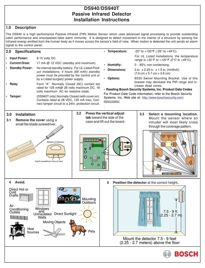
Select a location for mounting the detector that is most likely
to intercept an intruder moving across the coverage pattern.
The recommended mounting height range is 2 m to 2.6 m
(6.5 ft to 8.5 ft).
Mount to a surface that is solid and vibration-free. Avoid
direct hot and cold drafts, direct sunlight, heat sources,
windows, air conditioning outlets, and small animals. This
detector does not detect through glass.
Refer to Section 9.
NOTICE!
For bracket mounting, refer to the instructions
supplied with the bracket.
1. To remove the cover, insert a thin slotted screwdriver
into the notch at the bottom of the cover and pry up.
2. Remove the chassis screw in the upper right corner of
the assembly. To remove the circuit board/mirror unit
from the enclosure, push the circuit board/mirror unit
toward the top of the enclosure until it clears its four
retainer tabs, then lift out.
3. Mark the location for the mounting screws. Use the
enclosure as a template. Start the mounting screws.
4. Open the appropriate wiring knockout and route the
wiring through (Refer to Section 3.0).
5. Securely attach the detector.
6. Replace the circuit board/mirror unit.
7. Adjust the mirror.
2.1 | Mounting
NOTICE!
Excessive handling of the mirror surfaces lead to
performance degradation.
NOTICE!
Only apply power after all connections have been
made and inspected.
1. Adjust vertically from +2° to -18° by sliding the mirror
forward or back. Refer to Figure 2.1 to set the correct
vertical angle based on the mounting height and desired
range. Angle adjustment marks are on the sides of the
mirror (refer to Figure 2.2).
2. Slide the mirror forward or back until the angle hash
marks are in-line with the markers on each side of the
frame.
For narrow hallways, adjust the mirror horizontally to
enable proper coverage. By default, the detector pattern is
centered, leaving a gap in the coverage pattern down most of
the hallway (refer to Figure 2.3). Adjust the detector pattern
(mirror) to remove this coverage gap (refer to Figure 2.4).
Mount the detector and adjust the mirrors to provide proper
coverage.
Adjust the mirror vertically to enable proper coverage.
Figure 1.1: Detector base interior view (top) and detector body
interior view (bottom)
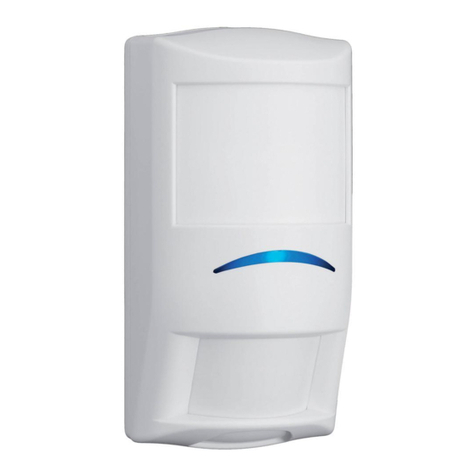
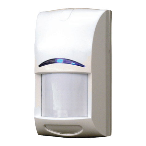
The DS778 is a long range, passive infrared intrusion detector
with pointable mirrored optics.
5
6
7
10
8
9
Figure 2.3: Narrow hallway, detector centered, pattern
centered
Figure 2.4: Narrow hallway, detector centered, pattern
rotated 1
°
(1 click)
Bosch Security Systems, Inc.
130 Perinton Parkway
Fairport, NY 14450
USA
www.boschsecurity.com
© 2016 Bosch Security Systems, Inc. F.01U.309.561 | 04 | 2016.08
Copyright
This document is the intellectual property of Bosch Security
Systems, Inc. and is protected by copyright. All rights reserved.
Trademarks
All hardware and software product names used in this
document are likely to be registered trademarks and must be
treated accordingly.
Bosch Security Systems, Inc. product manufacturing dates
Use the serial number located on the product label and refer to
the Bosch Security Systems, Inc. website at
http://www.boschsecurity.com/datecodes/.
11 | Specifications
Input power 6 VDC to 15 VDC; 18 mA at 12 VDC
Operating
temperature
The storage and operating range is
-40°F to +120°F (-40°C to +49°C).
For UL Certificated installations, the
temperature range is +32°F to +120°F
(0°C to +49°C).
Coverage 60 m by 4.5 m (200 ft by 15 ft)
Sensitivity
selection
Adjustable for Intermediate or High
Alarm relay Form “C” reed relay with contacts rated
at 28 VDC, 125 mA maximum for DC
resistive loads.
Tamper Normally closed (with cover in place)
tamper switch rated at 28 VDC, 125 mA
maximum
LED operation On/Off selectable
Standby power No internal standby battery. Unit is
intended to be connected to DC power
sources capable of supplying standby
power in the event primary power
fails. 18 mAh are required for each
hour of standby time needed. For UL
Certificated Installations, a minimum of
4 hours (72 mAh) is required.
10 | Coverage patterns
9 | Masking
1. Replace the cover.
2. Apply power to the unit.
3. Wait at least two minutes to start the walk test.
4. Walk test across the coverage pattern. Refer to Figure
6.1.
5. Determine the edge of the coverage by activating the
alarm LED. This changes depending upon the sensitivity
switch settings.
6. Walk test the unit from both directions to determine the
boundaries.
7. If you cannot achieve the desired range, try angling the
mirror up or down to assure the coverage pattern is not
aimed too high or low.
6 | Walk test
Figure 6.1 Walk test pattern
1. Connect a DC VOM to the Noise Voltage pins (use TC6000).
2. Replace the cover, routing the TC6000 cable through the
notch in the top of the case.
3. Set meter scale for about 3.0 VDC.
4. The base reference level for reading background noise is
approximately 2.0 VDC.
7 | Final tests
-B
+R
-W
NOTICE!
Meter readings are very important in determining
background disturbance levels and catch margin
sensitivity.
Figure 7.1 Meter reading
Use an ohm/volt meter to measure the background noise
voltage.
8 | Maintenance
At least once a year, check the range and coverage in
accordance with Section 5.
Instruct the end user to walk through the outer edge of the
coverage pattern. This ensures an alarm output prior to
arming the system.
Before attempting any masking, be sure the mirror surface
is the correct one. Use Figure 10.1 to determine the
relationship between mirror sections and the pattern.
Attempting to remove masking might destroy the mirror
surface or leave enough residue behind to reduce coverage
performance. Refer to Figures 9.1 and 10.1.
Figure 9.1 Mirror segment to pattern reference
Figure 10.2 Top view
Figure 10.1 Side view
5. Installations in quiet environments result in a steady reading
between 1.9 VDC and 2.1 VDC.
6. Voltage changes greater than 0.75 VDC from the reference
level are desirable for good catch performance.
7. If changes are less than +0.75 VDC, the device might fail to
respond if the temperature between the intruder and the
background is minimal.
8. Turn on all heating and cooling sources that are normally in
operation during times of protection.
9. Stand away from the unit and outside the coverage pattern,
then monitor the background noise for at least 3 minutes.
10. Readings should not deviate from the reference level by
more than ±0.15 VDC.
11. For readings outside these limits; eliminate the cause, re-
aim the unit slightly, or mask off the affected zones.
Sensitivity Switch 2 Switch 3
High
ON OFF
Intermediate
OFF ON
Not recommended
ON ON
Figure 5.1: Sensitivity swtich settings
Bosch Sicherheitssysteme GmbH
Robert-Bosch-Ring 5
85630 Grasbrunn
Germany
en Installation Guide
Long Range PIR Detector
DS778

Other Bosch Security Sensor manuals

Bosch ISC-SM-90 User manual

Bosch

Bosch ISC-SM-90 User manual

Bosch DMF 10 Zoom User manual

Bosch

Bosch DMF 10 Zoom User manual

Bosch F220 User manual

Bosch

Bosch F220 User manual

Bosch FCS-LWM-1 User manual

Bosch

Bosch FCS-LWM-1 User manual

Bosch Blue Line Q1 User manual

Bosch

Bosch Blue Line Q1 User manual

Bosch ZX835 User manual

Bosch

Bosch ZX835 User manual

Bosch ISW-ZPR1-WP13 User manual

Bosch

Bosch ISW-ZPR1-WP13 User manual

Bosch ISA-WM-869 User manual

Bosch

Bosch ISA-WM-869 User manual

Bosch Professional Series User manual

Bosch

Bosch Professional Series User manual

Bosch TriTech DS950 Series User manual

Bosch

Bosch TriTech DS950 Series User manual

Bosch RADION TriTech RFDL-11 User manual

Bosch

Bosch RADION TriTech RFDL-11 User manual

Bosch DS935Z User manual

Bosch

Bosch DS935Z User manual

Bosch FCP-O 500 User manual

Bosch

Bosch FCP-O 500 User manual

Bosch RADION contact SM User manual

Bosch

Bosch RADION contact SM User manual

Bosch TriTech+ ISC-PDL1-WA18G User manual

Bosch

Bosch TriTech+ ISC-PDL1-WA18G User manual

Bosch PMD 7 User manual

Bosch

Bosch PMD 7 User manual

Bosch Anatel Professional Series User manual

Bosch

Bosch Anatel Professional Series User manual

Bosch D-tect 150 Professional User manual

Bosch

Bosch D-tect 150 Professional User manual

Bosch DS306E User manual

Bosch

Bosch DS306E User manual

Bosch DS308EA User manual

Bosch

Bosch DS308EA User manual

Bosch RF940U User manual

Bosch

Bosch RF940U User manual

Bosch DS1109i User manual

Bosch

Bosch DS1109i User manual

Bosch MS-LZS User manual

Bosch

Bosch MS-LZS User manual

Bosch Truvo User manual

Bosch

Bosch Truvo User manual

Popular Security Sensor manuals by other brands

Steren VCA-500 instruction manual

Steren

Steren VCA-500 instruction manual

CPS Pro-Set LDA1000UV Operation manual

CPS

CPS Pro-Set LDA1000UV Operation manual

Interlogix PB501 Installation sheet

Interlogix

Interlogix PB501 Installation sheet

Johnson Controls MP-802 PG+ installation guide

Johnson Controls

Johnson Controls MP-802 PG+ installation guide

Airthings Wave Plus operating manual

Airthings

Airthings Wave Plus operating manual

Kyla KSEN-231 Easy start guide

Kyla

Kyla KSEN-231 Easy start guide

Nexa ROMDT-810 user manual

Nexa

Nexa ROMDT-810 user manual

Sony Digiruler PL21 instruction manual

Sony

Sony Digiruler PL21 instruction manual

Eaton URTDII Instruction leaflet

Eaton

Eaton URTDII Instruction leaflet

NookBox IRD-23 installation guide

NookBox

NookBox IRD-23 installation guide

AVS Electronics WING WS manual

AVS Electronics

AVS Electronics WING WS manual

Buckingham 6263 Series instructions

Buckingham

Buckingham 6263 Series instructions

ITALIANA SENSORI 8001-ISR001 Installation, operation and maintenance manual

ITALIANA SENSORI

ITALIANA SENSORI 8001-ISR001 Installation, operation and maintenance manual

RKI Instruments GD-K7D2 Operator's manual

RKI Instruments

RKI Instruments GD-K7D2 Operator's manual

Potter PAD300-4DB quick start guide

Potter

Potter PAD300-4DB quick start guide

Pittway ECO1005 Installation and maintenance instructions

Pittway

Pittway ECO1005 Installation and maintenance instructions

Satel COBALT Pro user manual

Satel

Satel COBALT Pro user manual

Magna ICON MRRICONV01 user manual

Magna

Magna ICON MRRICONV01 user manual

manuals.online logo
manuals.online logoBrands
  • About & Mission
  • Contact us
  • Privacy Policy
  • Terms and Conditions

Copyright 2025 Manuals.Online. All Rights Reserved.