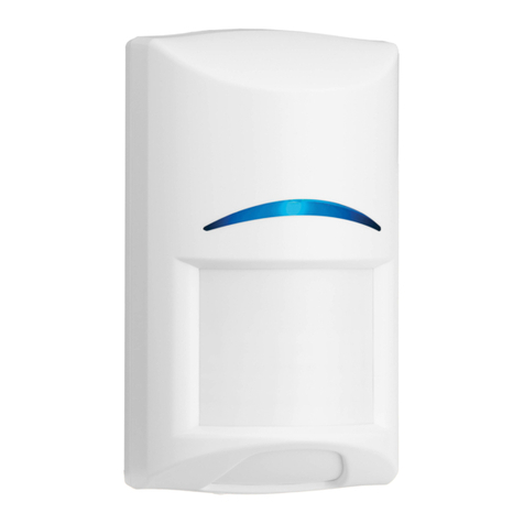
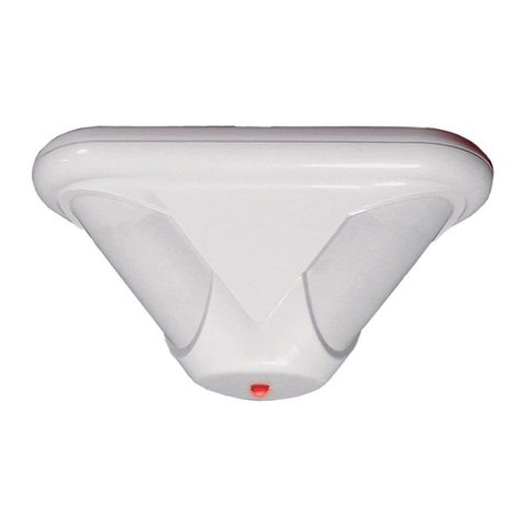
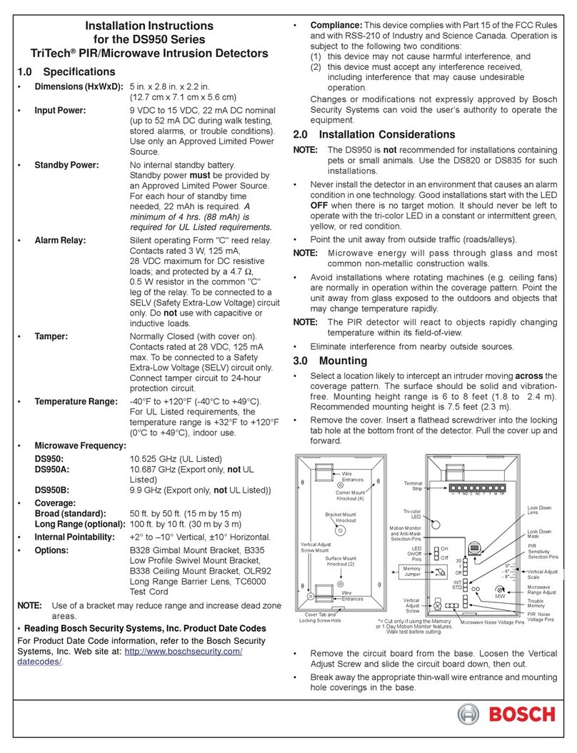
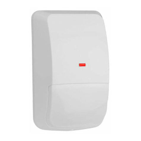
Bosch ZX835 User manual

1.0 Specifications
•Input Power: 9 to 15 VDC, 6 mA nominal (35 mA with LED on).
•Standby Power: There is no internal standby battery. Connect to standby power as a backup in the event primary power
fails.SixmA-Hrequiredforeachhourofstandbytimeneeded.FourhoursminimumisrequiredforULListedRequirements.
•Temperature: The operating temperature range is -20° to +120°F (-29° to +49°C). For UL Listed Requirements, the
temperature range is +32° to +120°F (0° to +49°C).
•Microwave Frequency: 10.525 Ghz, ±25.000 Mhz.
•Coverage: 35 ft. by 35 ft. (10.7 m by 10.7 m)
•Internal Pointability: +2° to –10° Vertical, ±10° Horizontal.
•Tamper: Tamper condition transmitted through the Zonex bus when the cover is removed.
•Requirements: Requires a compatible control panel with a POPEX module installed.
•Options: B328 Gimbal Mount Bracket, B335 Low Profile Swivel Mount Bracket (use of a bracket may reduce range and
deadzoneareas).
•U. S. Patent Numbers: #4,660,024; #4,764,755; #5,077,548; #5,208,567; #5,262,783; #5,450,062. Other patents pending.
2.0 Installation Considerations
• Never install the detector in an environment that causes an alarm condition in one technology.Good installations start with
the LED OFF when there is no target motion. It should never be left to operate with the tri-color LED in a constant or
intermittent green, yellow, or red condition.
• Point the unit away from outside traffic (roads/alleys). Remember: Microwave energy will pass through glass and most
common non-metallic construction walls. Avoid installations where rotating machines (e.g., ceiling fans) are normally in
operation within the coverage pattern.
• Pointtheunitawayfromglassexposedtotheoutdoorsandobjectsthatmaychangetemperaturerapidly.Remember: ThePIR
detector will react to objects rapidly changing temperature within its field-of-view.
• Eliminate interference from nearby outside sources.
3.0 Mounting
1. Select a location likely to intercept an intruder moving across the
coverage pattern. The surface should be solid and vibration free.
Mounting height range is 6 to 8 ft. (1.8 to 2.4 m). Recommended
mounting height is 6.5 ft. (2 m).
2. Remove the cover. Insert a flathead screwdriver into the locking tab
holeatthebottomfrontofthedetector.Pullthecoverupandforward.
3. Mount the unit with the terminal block up.
4. Remove the circuit board from the base. Loosen the Vertical Adjust
Screw and slide the circuit board down then out.
5. Break away the appropriate thin-wall wire entrance and mounting
hole coverings in the base.
6. Using the base as a template, mark the location of the holes on the
mounting surface.
7. Route wiring (unpowered) as necessary. Route to the rear of the base and through the wire entrance.
8. Firmly mount the base to the mounting surface.Return the circuit board to the base and tighten theVertical Adjust Screw.
Microwave PIR Detector with POPIT Interface ZX835
Installation Instructions

ZX835 Installation Instructions
35985G Page 2 © 2003 Bosch Security Systems
ZX835
4.0 Programming
Program the address DIP switches as described for the control panel you are using.
Note: When installing the ZX835 with a D7212B1, D8112, or D9112B1; place switch number “0” in the ON position.
Recommended point type programming: D8112 = 7571
D9112B1/D7212B1 = Point type 2, point response 2, no ring until restored.
D9412/D9112 = Point type 2, point response E, no ring until restored.
5.0 Wiring
Apply power after all connections have been inspected. Do not coil excess wiring inside. Plug the wire entrance hole
with the foam plug provided after all wiring connections have been made.
6.0 LED Operation
The detector uses a tri-color LED to indicate the various alarm and supervision trouble conditions that may exist
If the detector experiences a Microwave or PIR self-test failure, it is in need of replacement.
Duringwalktesting,theLEDwilllightforthefirsttechnology(microwaveorPIR)andthenlightredtoindicateadetectoralarm.TheLED
will not indicate activation of the second technology by lighting its color.
7.0 Feature Selection
•LED On/Off Pins: The ON position allows operation of the tri-color LED.
If the tri-color LED indication is not desired after setup and walk tests are
completed, place the plug in the OFF position. The OFF position does not
prevent the tri-color LED from indicating a supervision trouble condition.
•PIRSensitivitySelectionPins: ThePIRresponsesensitivity may be selected
by placing the plug across the pins marked (STD) for Standard or (INT) for
Intermediate mode.
-Standard Sensitivity: The recommended setting for maximum false alarm immunity. Tolerates environmental
extremes on this setting.
-Intermediate Sensitivity: The recommended setting for non-pet applications where an intruder is expected to cover
only a small portion of the protected area. Tolerates normal environments on this setting. This setting will improve
yourintruder catchperformance. (Recommended forhigher mountingheights).
8.0 Setup and Walk Tests
Select the vertical starting angle from the chart. To adjust the vertical starting angle for the desired mounting height and range, loosen the
vertical adjust screw and slide the board up, to point the angle down. Note the settings on the vertical adjust scale.
CAUTION
LED CAUSE
Steady red Unit alarm
Steady yellow Microwave activation (walk test)
Steady green PIR activation (walk test)
Flashing red Warm-up period after power-up
Flashing red (4-pulse sequence) Microwave or PIR failure; replace unit

ZX835
ZX835 Installation Instructions
© 2003 Bosch Security Systems Page 3 35985G
Note: A mounting height of 6 1/2 ft. (2 m) and the proper vertical angle must be selected for
installations containing pets. See Section 12.0 Special Instructions, p. 4.
•Place the LED plug in the ON position.
•Wait at least two minutes, after applying power, to start walk tests.
Note: During the warm-up period, the tri-color LED will flash red until the unit has stabilized and
has seen no movement for two seconds (approx. 1 to 2 minutes). When the LED stops flashing,
the detector is ready to be tested. With no motion in the protection area, the LED should be OFF. If the LED is on, re-check
the protection area for disturbances affecting the microwave (yellow) or PIR (green) technologies.
8.1 Establishing PIR Pattern Coverage
1. Turn the Microwave range adjust to minimum and replace the cover.
2. Walk test across the pattern at its farthest edge, then several times closer to the detector. Start walking from outside of the
intended protection area, and observe the tri-color LED. The edge of the pattern is determined by the first green, PIR
activation of the LED (or the first red activation if the yellow microwave LED activates first).
3. Walktestfromtheoppositedirectiontodeterminebothboundaries.Thecenterofthepatternshouldbepointedtowardthe
center of the intended protection area.
4. Slowly bring your arm up and into the pattern to mark the lower boundary on PIR alarm. Perform this task at 10 to 20 ft.
(3.1 to 6.1 m) from the unit. Repeat from above for the upper boundary. The center of the pattern should not be tilted
upward.
5. If desired coverage can not be achieved, try angling the coverage pattern up or down to assure the pattern is not aimed too
high or low. For pet applications, do not adjust below recommended angle. The angle of the PIR pattern may be vertically
positioned between -10° and +2° by loosening the Vertical Adjust screw and sliding the circuit board up or down.
Moving the board up will angle the pattern downward. Tighten the screw snug when positioning is completed.
Note:The pattern may be moved ±10° horizontally by moving the lens window left/right.
8.2 Establishing Microwave Coverage
Note:It is important to wait one minute after removing/replacing the cover so the microwave portion of the detector can settle,
and to wait at least 10 seconds between the following walk testing procedures.
• The tri-color LED should be OFF before walk testing.
1. Walk test across the pattern at the intended coverage’s farthest end. Start walking from outside the intended protection
areaandobservethetri-colorLED.Theedgeofthemicrowavepatternisdeterminedbythefirstyellow,microwaveactivation
of the LED (or the first red activation if the green PIR LED activates first).
2. If adequate range can not be reached, increase the Microwave Range Adjust slightly. Continue walk testing (waiting one
minute after removing/replacing the cover) and adjusting the range until the farthest edge of desired coverage has been
accuratelyplaced.
Note: Do not adjust the microwave range higher than required. Doing so will enable the detector to catch movement outside of the
intended coverage pattern.
• Walk test the unit from all directions to determine all the detection pattern boundaries.
8.3 Establishing Detector Coverage
•The tri-color LED should be OFF before walk testing.
• Walk test the unit from all directions to determine the detection boundaries. A detector alarm is signaled by the first red
activation of the tri-color LED after an initial green or yellow activation.
9.0 Supervision Features
The supervision features function as follows:
•PIR/Microwave: The complete circuit operation of these subsystems is tested approximately every 6 hours. If the PIR or
microwave subsystem fails,a second test is performed after one hour. If the PIR or microwave subsystem fails the second test,
the tri-color LED will flash red 4 times per cycle and the unit should be replaced.
•Default: Thedetectorwilldefaultto PIR technologyprotectionifthemicrowavesubsystemfails.Whendefaulting to PIR,the
PIR signal processing will change from INT to STD sensitivity.
© 2003 Bosch Security Systems 35985G 08/03
130 Perinton Parkway, Fairport NY 14450-9199 USA Installation Instructions ZX835
Customer Service: (800) 289-0096; Technical Support: (888) 886-6189 Page 4 of 4
10.0 Other Information
Maintenance: At least once a year, the range and coverage should be verified.To ensure continual daily operation, the end user should be
instructed to walk through the far end of the coverage pattern. This ensures an alarm output prior to arming the system.
Pattern Masking: The PIR coverage pattern may be masked using masking tape or electrical tape on the inside of the lens.
Note:Masking only eliminates the PIR portion of the coverage and has no effect on the microwave pattern.
11.0 Coverage Pattern
Theprotectedcoverage area iswhere the microwaveandPIR patterns overlap.
An optional Look Down lens is located under the detector. This lens must be unmasked before it is operational. The Look Down lens is
not recommended for installations containing pets or small animals. The Look Down finger is shown in black below.
12.0 Special Instructions for Installations Containing Pets
The ZX835 will provide reasonable protection from nuisance alarms caused by the following sources:
• A dog up to 100 pounds (45 kg) • Up to 10 cats
• Two 60 pound (27 kg) dogs • Random flyingbirds
• Multiple small rodents, such as rats
To take full advantage of the ZX835’s Signature Recognition Technology, the following guidelines
shouldbe followed:
• Mount the detector 6½ ft. (2 m) high and adjust the PIR angle to -5°.
•Set the PIR sensitivity for Standard (STD).
• Mount where the animals cannot come within 6 ft. (1.8 m) of the detector by climbing
on furniture, boxes or other objects.
• Do not remove the Look Down lens mask.
• Don’t aim the detector at stairways the animals can climb on.
• Adjustthemicrowaverangefortheminimumacceptablecoveragefortheroominwhich
the detector is installed.
Note: Pet avoidance is only available when using the lens provided with the detector.
This nuisance protection has not been verified by Underwriter’s Laboratories, Inc.
Table of contents
Other Bosch Security Sensor manuals

Bosch
Bosch PAVIRO Series User manual

Bosch
Bosch DS936 User manual

Bosch
Bosch DS835I Series User manual

Bosch
Bosch RADION contact SM User manual

Bosch
Bosch ISC-PPR1-W16G User manual

Bosch
Bosch GMS 120 User manual

Bosch
Bosch Blue Line D1-P User manual

Bosch
Bosch Blue Line Q1 User manual

Bosch
Bosch Blue Line D1-P User manual

Bosch
Bosch DS820 Safety guide

Bosch
Bosch DS820i Series User manual

Bosch
Bosch ISC-BDL2-W12 User manual

Bosch
Bosch DS794Z User manual

Bosch
Bosch DS820i Series User manual

Bosch
Bosch ISP-PPR1-WA16x User manual

Bosch
Bosch D-tect 150 Professional User manual

Bosch
Bosch ISN-SM-50 User manual

Bosch
Bosch RF920 User manual

Bosch
Bosch ISC-BDL2-WP12 User manual

Bosch
Bosch DS 935 LSN User manual