2 © 2012 Bosch Security Systems, Inc.
EN 50131-2-4 Grade 2
EN 50130-5 Environmental Class II
IP30 IK04 (EN 60529, EN 62262)
0 - 95% Relative Humidity
(0 - 85% UL/C-UL Installations)
-40°C to +49°C
(-40°F to +120°F )
UL Listed
installations,
the temperature
range is 0°C to +49°C
(+32°F to +120°F)
Pour les
installations
certifiées NFA2P,
Température de
fonctionnement
-10°C à +55°C
För svensk installationsanvisning se www.boschsecurity.se.
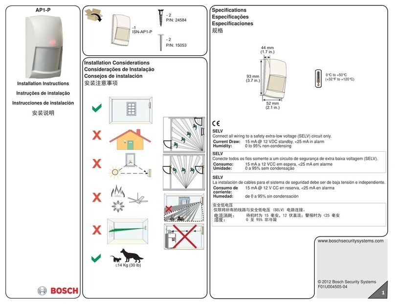
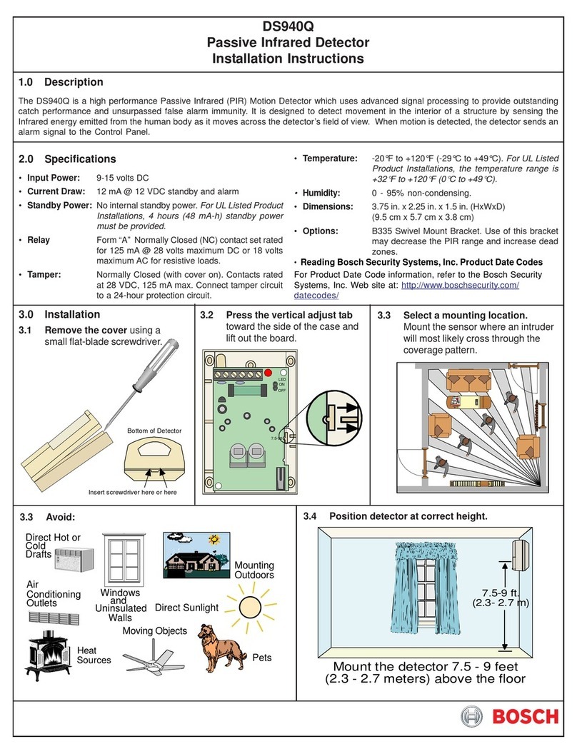
Specifications
Dimensions
(HxDia) 3.5 in. x 5.25 in. (8.9 cm x 13.3 cm)
Input
Power 6.0 to 15.0 VDC; 8 mA standby, 60 mA in alarm with LEDs enabled. Use only an Approved
Limited Power Source.
Standby
Power There is no internal standby battery. Standby power must be provided by an Approved
Limited Power Source. Eight mAh required for each hour of standby time needed. For UL
Listed Requirements, 32 mAh standby current is required.
Alarm Relay Silent-operating Form “C” relay. Contacts rated <100 mA, 25 VDC, 2.5W <20 Ohm closed
maximum for DC resistive loads.
Tamper Contacts rated at 28 VDC, 125 mA maximum, <1 Ohm. To be connected to a SELV (Safety
Extra-Low Voltage) circuit only. Connect tamper circuit to a 24-hour protection circuit.
Compliance This device complies with Part 15 of the FCC Rules. Operation is subject to the following
two conditions:
(1) this device may not cause harmful interference, and
(2) this device must accept any interference received, including interference that may
cause undesirable operation.
This product is intended for use in the following
countries within the European Union and in other
countries outside of the European Union:
Austria, Belgium, Denmark, Finland, Greece, Luxembourg, Netherlands, Norway, Spain, Sweden, Italy
SELV
Connect all wiring to a safety extra-low voltage (SELV) circuit only.
Ligue todas as cablagens apenas a um circuito de segurança de tensão extra baixa.
Conecte el cableado únicamente a un circuito de seguridad para voltajes muy bajos.
Alle Drähte sind ohne Ausnahme an Niederspannung anzuschließen.
Sluit alle bedrading uitsluitend aan op een circuit met een extra lage veiligheidsspanning.
Prenez soin de connecter tous les câbles à un circuit à très basse tension de sécurité (TBTS).
Collegare tutti i cavi esclusivamente a un circuito di sicurezza a bassissima tensione.
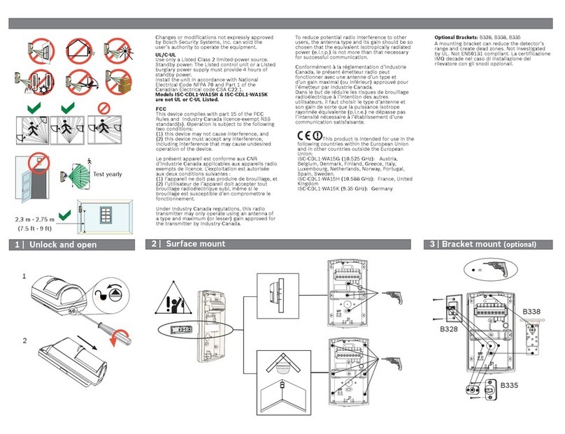
Changes or modifications not expressly approved
by Bosch Security Systems, Inc. can void the user’s
authority to operate the equipment.
UL/C-UL
Perform Walk Test at least once a year.
Use only a Listed limited-power source.
The Listed control unit or a Listed burglary power
supply must provide 4 hours (32 mAh) of standby
power.
Install the unit in accordance with National
Electrical Code NFPA 70 and Part 1 of the Canadian
Electrical code CSA C22.1.
Adjust the microwave range control, if necessary, to
achieve maximum range.
F.01U.263.664 | 01 | 05.2012 | 7
NOTICE!
During walk testing, the LED will light for the first technology (micro-
wave or PIR) and then light red to indicate a detector alarm. The LED
will not indicate activation of the second technology by lighting its
color.
LED
OFF ON
I H
Sensitivity
Jumper
IH
OFF ON
LED
Jumper
7 Feature Selection
7.1 LED On/Off Pins
The ON position allows operation of the tri-color LED. If LED indication is
not desired after setup and walk tests are completed, place in the OFF po-
sition. The OFF position does not prevent the LED from indicating supervi-
sion trouble conditions.
7.2 PIR Sensitivity Selection Pins
For selection, place the plug across the pins marked I for Intermediate
mode or H for High mode.
• Intermediate Sensitivity (I): Tolerates environment extremes on this
setting, but requires the largest amount of intruder motion to achieve
an alarm.
• High Sensitivity (H): The recommended setting for most installations.
Use in locations where an intruder is expected to cover only a small
portion of the protected area. Tolerates normal environments on this
setting. The detector is shipped in High Sensitivity mode.
7.3 Microwave Adjustment
NOTICE!
It is important to wait 1 minute after removing/replacing the cover so
the microwave portion of the detector can settle, and to wait at least 5
seconds between the following walk testing procedures.
1. The tri-color LED should be off before walk testing.
2. Walk test across the pattern at the intended coverage’s farthest end.
Start walking from outside the intended protection area and observe
the tri-color LED. The edge of the microwave pattern is determined
by the first tri-color, microwave activation of the LED (or the first red
activation if the green PIR LED activates first).
Figure 6.1: Selecting features
