ATTACHING THE
EAP ASSEMBLY
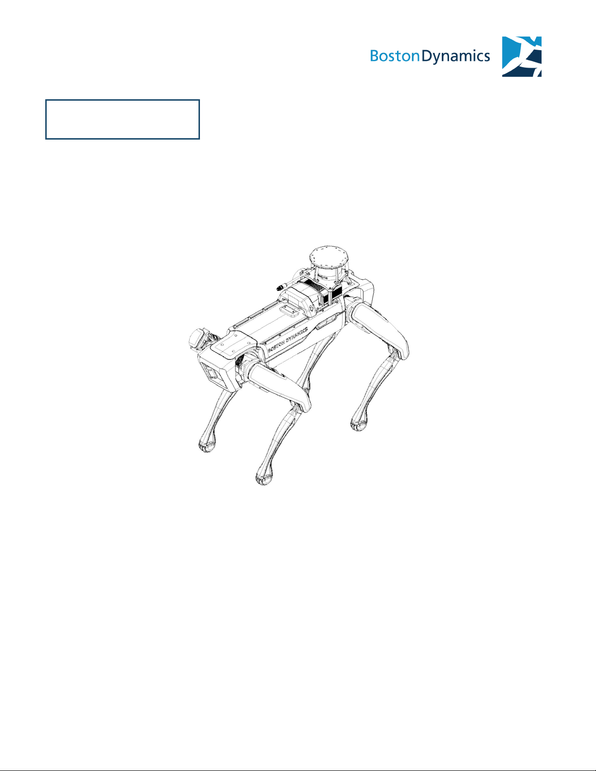
The Spot EAP can be attached to the robot in the rear position and connected to
the rear payload port. The CORE unit is oriented with the GXP towards the front
of the robot.
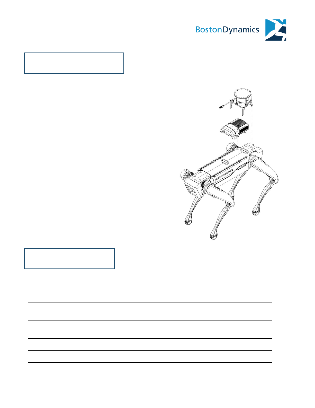
ATTACH THE SPOT CORE AND LIDAR UNIT TO THE ROBOT
Parts needed
●Spot CORE unit
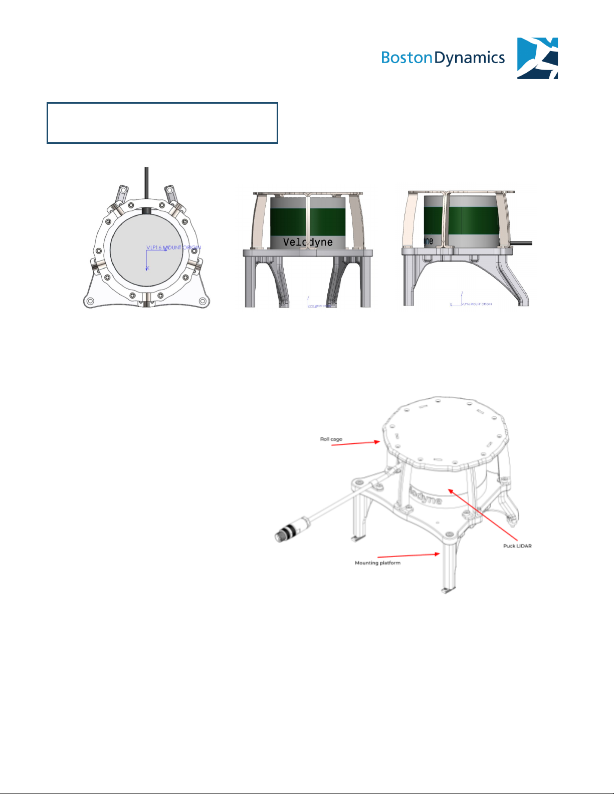
●LIDAR unit
●Four M5x8 socket head screws for CORE
●Two M5x20 socket head screws for
LIDAR
●Two M5x80 socket head screws for
LIDAR
●Two M5 10mm spacers
●Six t-slot nuts
1. Power down the robot and position it on the ground or on a bench in sit pose.
2. Lay the Spot CORE assembly on the back of the robot with the GXP facing toward
the front of the robot and the ribbon cable pointed to the rear.
3. Remove the rear payload port cap and keep in a safe place. The robot will not
operate without the payload cap or a payload attached to the port.
4. Attach the free end of the payload cable to the port and tighten the mounting
screws to 0.2 N*m.
5. Insert three t-slot nuts on each side of the payload rails, taking care that the tip of
the set screw is pointed down. Loosen the set screw, if needed, to fit the nut into
the slot so that it lays flat and moves freely. Do not tighten the set screws.
6. Slide the t-slot nuts into position under the four connection points in the CORE
base plate. The CORE will utilize the front most and rear most t-slot nut.
7. The LIDAR mount will utilize a t-slot nut between the two CORE t-slot nuts and two
rear bolt holes on Spot. Remove the two rear M5 bolts, keep those in a safe place.
8. Apply threadlocker to the four 8mm socket head screws for CORE and two 80mm
for LIDAR) and thread each one into a t-slot nut. Finish by tightening the four
socket head screws to 5 N*m.
Boston Dynamics proprietary & confidential 10