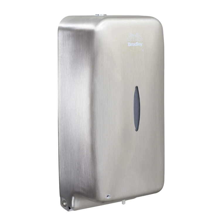
Bradley Verge Crestt Series Manual

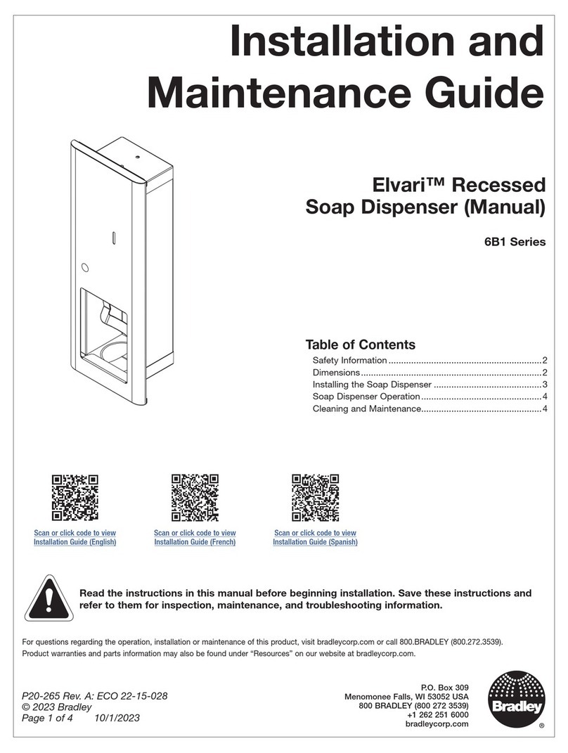
Installation and
Maintenance Manual
P.O. Box 309
Menomonee Falls, WI 53052 USA
800 BRADLEY (800 272 3539)
+1 262 251 6000
bradleycorp.com
P20-225 Rev. A: ECO 19-15-015A
© 2020 Bradley
Page 1 of 19 2/12/2020
Verge®Multi-Feed Soap Tank
Verge®Soap Dispenser -Crestt Series (6-3100)
Verge®Soap Dispenser - Metro Series (6-3300)
Verge®Soap Dispenser -Linea Series (6-3500)
Verge®Soap Dispenser -Zen Series (6-3700)
Table of Contents
Safety Information ............................................................... 2
Supplies Required ............................................................... 2
Components ........................................................................ 3
Dimensions.......................................................................... 4
Soap Spout Mounting.......................................................... 5
Control Box Mounting .......................................................... 6
Control Box & Soap Supply Connections............................ 7
Multi-Feed Soap Tank Assembly Mounting ......................... 8
Soap Supply Connections ................................................. 12
Power Supply Connections................................................ 16
Adding Soap to Multi-Feed Soap Tank Assembly ............. 17
Operation Mode................................................................. 18
Cleaning and Maintenance................................................ 19
Liquid Soap Recommendations / Maintenance................. 19
Read the instructions in this manual before beginning installation. Save these
instructions and refer to them for inspection, maintenance, and troubleshooting
information.
For questions regarding the operation, installation or maintenance of this product, visit bradleycorp.com or call
800.BRADLEY (800.272.3539).
Product warranties and parts information may also be found under “Resources” on our website at
bradleycorp.com.
NOTE: Refer to the Installation and Maintenance Manual, P20-224 for individual automatic top-fill soap dispensers.

Verge®Multi-Feed Soap Tank Installation
22/12/2020 Bradley • P20-225 Rev. A: ECO 19-15-015A
Safety Information
Caution
A DC plug-in adapter (supplied by Bradley) should be used in conjunction with the Bradley soap dispenser products. The DC
plug-in adapter supplied by Bradley is 6V DC regulated. Direct connection to 120V/22V 50/60Hz could result in personal injury and
will damage the sensor.
Important
Separate parts from packaging and make sure all parts are accounted for before discarding packaging material. If any parts are
missing, do not begin installation until you obtain the missing parts.
Troubleshooting and internal maintenance must be performed by qualified service personnel.
Supplies Required
• (1) dedicated 120VAC, 20A GFCI outlet(s), if an A14-029 or A14-031 AC adapter is selected
• Drill
• 1/4” drill bit
• Tape measure
• Phillips screw driver
• Level
• Pencil
• Tubing cutter

Installation Verge®Multi-Feed Soap Tank
Bradley • P20-225 Rev. A: ECO 19-15-015A 2/12/2020 3
Components
Allen Key
Silicone Washer
Locking Tab
Wing Nut
Multi-Feed
Control Box
Multi-Feed
Cap & Ring
Soap Pump
(Liquid w/Tube)
Soap Pump
(Foam w/Tube)
OR
OR
OR
Multi-Feed
Soap Tank
Assembly
Soap Spout
Assembly
Power Supply Options
AC Adapter
Battery Pack
w/Batteries
AC Adapter
Splitter Assembly

Verge®Multi-Feed Soap Tank Installation
42/12/2020 Bradley • P20-225 Rev. A: ECO 19-15-015A
Dimensions (mm)
4⁷⁄₁₆"
(112)
5⁷⁄₁₆"
(138)
3¹¹⁄₁₆"
(93)
4³⁄₈"
(111)
4"
(101)
3¹⁵⁄₁₆"
(100) 2¹¹⁄₁₆"
(68)
4³⁄₄"
(120)
3⁵⁄₁₆"
(84)
4¹⁄₈"
(104)
4³⁄₁₆"
(106)
4⁷⁄₈"
(123)
4³⁄₁₆"
(106) 2³⁄₁₆"
(55)
2¹³⁄₁₆"
(71)
4¹⁄₁₆"
(103)
6-3100 Crestt Series
6-3500 Linea Series
6-3300 Metro Series
6-3700 Zen Series

Installation Verge®Multi-Feed Soap Tank
Bradley • P20-225 Rev. A: ECO 19-15-015A 2/12/2020 5
Soap Spout Mounting
Verify the soap spout shank &
silicone washer sit flat on the deck.
Verify there is 2-1/8"diameter
clearance under the side of the
deck for the locking tab.
Repeat this procedure for each soap spout assembly (maximum of 6 per system).
1
Soap Spout
Assembly
1-3/8" Dia.
Mounting Hole Locking Tab
LED Location
Locking Tab
Deck
Soap Supply
Wing Nut
Wing Nut
Key Way
LED & Sensor
Wires
Place the silicone washer under the soap
spout assembly. Align with the emboss
on the bottom side of the shank.
A
Carefully insert the soap
supply & vent tubes, and the
LED & sensor wires through
the mounting hole.
B
Insert the soap spout shank through the
mounting hole.
C
Position the locking tab key in line with
the keyway on the shank.
D
Thread the wing nut onto the shank.
Torque to 24 in/lb.
F
Feed the soap supply and LED & sensor
wires through the opening in the locking
tab.
E

Verge®Multi-Feed Soap Tank Installation
62/12/2020 Bradley • P20-225 Rev. A: ECO 19-15-015A
Control Box Mounting
2
Use a level to ensure the control box
assembly is level, and then mark four
mounting hole locations on the wall using
a pencil.
B
Drill the four 1/4" diameter mounting
holes into the wall or surface, using a drill
and appropriate drill bit.
C
Fastener
Anchors
Mounting
Screws
Mounting Holes
x2
1/4"Dia.
Mounting
Holes
Locate the mounting position for the
control box assembly.
A
2¹⁄₂"Offset (max) Right or
Left From Center
Use the supplied mounting screws (or
suitable mounting hardware) to attach the
control box assembly in place.
D
Top mounting holes need to be
mounted between 4¹⁄₂"& 9¹⁄₂"from
the top of the deck, and 2¹⁄₂"right or
left of center of shank.
Appropriate fastener anchors and
mounting hardware must be used
when mounting the control box
assembly in the desired surface.
4¹⁄₂" (114)
9¹⁄₂" (241)
10½"
(267)
3¹⁄₈" (79)
Shank

Installation Verge®Multi-Feed Soap Tank
Bradley • P20-225 Rev. A: ECO 19-15-015A 2/12/2020 7
Control Box & Soap Supply Connections
3
IR Sensor Connection
from Soap
Spout Assembly
Power Supply
Connection
LED Connection
from Soap
Spout Assembly
Soap Supply Tube
from Soap Spout
Assembly
Make the IR sensor and LED,
connections as shown.
Press the soap supply tube over the soap
pump connection as shown.
C
D
Verify the soap pump is positioned below
the control box lever.
A
Verify the shoulder of the soap pump is
positioned above the control box groove.
B
Connections are NOT
interchangeable.

Verge®Multi-Feed Soap Tank Installation
82/12/2020 Bradley • P20-225 Rev. A: ECO 19-15-015A
Remove the Fill Port Hub Assembly
2
3
/
8
M
I
N
I
M
U
M
F
R
O
M
W
A
L
L
2-3/8" Dia.
Mounting Hole
Soap Overflow
Sensor (Black)
Lower Soap
Tank Bracket
Thumb
Screws
Thumb
Screws
Low Soap Sensor
Soap Supply Valve
Soap Tank
Mounting
Bracket
Soap
Tank
Lower Soap
Tank Bracket
Remove the four thumb screws at the bottom of
the soap tank mounting brackets, and slide the
lower soap tank bracket forward.
Slide the soap tank downward from the bracket
assembly to remove the soap tank from the
mounting bracket.
B
C
Carefully disconnect the soap sensors and the
LED connector.
ALED Connector
(White)
Power Supply
Connection
Low Soap Level
Sensor (Red)
Multi-Feed Soap Tank Assembly Mounting
4
Before mounting the soap tank assembly,
drill a 2-3/8"diameter hole through the deck
that is positioned 2-3/8"from the adjacent
back wall. This will ensure proper clearance
of the soap tank.

Installation Verge®Multi-Feed Soap Tank
Bradley • P20-225 Rev. A: ECO 19-15-015A 2/12/2020 9
Install Multi-Feed Components
LED and sensor wires are not shown
in this view for clarity purposes.
Remove the mounting nut from the fill port hub
assembly.
E
Carefully remove the fill port hub assembly
from the soap tank assembly.
D
Insert the fill port ring into the fill port hub and
align the mounting holes. Secure in place using
the four fill port screws.
A
Insert the fill port cap into the fill port ring. Use
the 3 mm Allen wrench (provided with spout
assembly) to secure fill port cap in place.
B
Fill Port Hub
Assembly
3 mm
Allen Wrench
Overflow
Sensor
Fill Port Cap
Fill Port Hub
Fill Port Ring
Soap Tank
Assembly
Low Soap
Sensor
Fill Port
Screws
Fill Port
Screws
Mounting Nut

Verge®Multi-Feed Soap Tank Installation
10 2/12/2020 Bradley • P20-225 Rev. A: ECO 19-15-015A
Stepped
Washer
Low Soap
Level Sensor
Hemmed Side of
Mounting Bracket
Soap
Tank
Install the fill port assembly through the 2-3/8"
diameter hole in the lav deck.
Place the stepped edge of the washer parallel
with the hemmed side of the mounting bracket.
Reposition the lower soap tank bracket into the
mounting bracket. Be sure to align the thumb
screw holes.
Thread the mounting nut onto the fill port hub
assembly. Hand-tighten or torque to 24 in-lb.
Position the mounting bracket with the stepped
washer over the threaded portion of the fill port
hub assembly (located below the deck).
Insert the four thumb screws into the mounting
bracket to hold the soap tank assembly in
place.
A
B
B
D
C
C
Install the soap tank onto the center of the fill
port hub assembly until the bottom of the soap
tank is flush with the returned edged of the
mounting bracket.
A
The distance between the soap dispenser
and the fill port hub assembly can only be a
maximum of 42"center to center.
Lav deck can only be a maximum of 1-1/2"
thick.
Mounting
Nut
Thumb
Screws
Lower Soap
Tank Bracket
Stepped Side
of Washer
Mounting
Bracket
Fill Port Hub
Assembly
Install Fill Port Hub Assembly on Lav Deck
Install Soap Tank onto Fill Port Hub Assembly
CAUTION Keep the LED wire positioned to the
side of the fill port hub assembly when
inserting the soap tank to prevent the
LED wire from getting pinched.

Installation Verge®Multi-Feed Soap Tank
Bradley • P20-225 Rev. A: ECO 19-15-015A 2/12/2020 11
Reconnect Soap Sensors & LED Connector
Soap Overflow
Sensor (Black)
LED Connector
(White)
Power Supply
Connection
Low Soap Level
Sensor (Red)

Verge®Multi-Feed Soap Tank Installation
12 2/12/2020 Bradley • P20-225 Rev. A: ECO 19-15-015A
Soap Supply Connections
5
See page 13 for an overview of the mid tank
configuration installation.
Install the soap supply valve in the proper
flow direction as shown on the valve.
Use the extra tubing when cleaning and/or
maintaining the soap system.
Tubing will slide 3/4"into the fittings.
End Tank Configuration Installation
Insert 3/8" diameter tubing into the soap supply
valve as shown. Connect the supply tube to the
nearest control box, cutting the supply tube to
the shortest length between units.
Cut one piece of tubing 3"–4" in length and
assemble as shown.
Install extra tubing after the shut off valve
(located at the end of the soap supply system).
Connect the soap supply tubes between the
control boxes, cutting the supply tube to the
shortest length between units. See illustration
on page 13.
A
C
D
B
Soap supply valve is
shown in the open
position.
Soap supply
valve is shown
in the closed
position.
IN
OUT
Soap supply valve is
shown in the open
position.

Installation Verge®Multi-Feed Soap Tank
Bradley • P20-225 Rev. A: ECO 19-15-015A 2/12/2020 13
DETAIL 1DETAIL 2DETAIL 3
12
3
42" MAX42" MAX
A
B B
C
CBB
B
A
D
D

Verge®Multi-Feed Soap Tank Installation
14 2/12/2020 Bradley • P20-225 Rev. A: ECO 19-15-015A
See page 15 for an overview of the mid tank
configuration installation.
Tubing will slide 3/4"into the fittings.
Mid Tank Configuration Installation
Cut one 1-3/4" piece of the 3/8" diameter tubing
and attach as shown.
Cut one piece of tubing 3"–4" in length and
place the tubing through the straps on both
sides of the control box as shown. Repeat this
step for both ends of the soap supply system.
Install extra tubing after the shut off valve
(located at both ends of the soap supply
system).
Connect the soap supply tubes between the
control boxes, cutting the supply tube to the
shortest length distance between units. See
illustration on page 15.
A
C
D
B
Soap supply valve is
shown in the open
position.
Soap supply
valve is shown
in the closed
position.
Soap supply valve is
shown in the open
position.
IN
OUT
Install the soap supply valve in the proper
flow direction as shown on the valve.
Use the extra tubing when cleaning and/or
maintaining the soap system.

Installation Verge®Multi-Feed Soap Tank
Bradley • P20-225 Rev. A: ECO 19-15-015A 2/12/2020 15
DETAIL 1DETAIL 2
DETAIL 3
1
23
42" MAX42 MAX
A
D
D
C
D
D
C
BBD

Verge®Multi-Feed Soap Tank Installation
16 2/12/2020 Bradley • P20-225 Rev. A: ECO 19-15-015A
Connect the power supply to the power
source for the multi-feed tank system.
A
Connect the power supply to the power
source for the multi-feed soap tank
assembly. When the connection is made,
the LED at the base of the soap dispenser
spout will flash green for 0.5 seconds.
B
Power Supply Connections
6
The multi-feed soap tank assembly
and each of the control boxes require a
power supply connection.
The power supply can be a Bradley
supplied battery pack, a single AC
adaptor, or an AC adapter splitter
assembly kit (see page 3), depending on
the selection made at time of purchase.
Location of the
Power Source
Connection
Control Box
Connection
Location of the
Power Source
Connection
Multi-Feed Soap
Tank Assembly
Connection

Installation Verge®Multi-Feed Soap Tank
Bradley • P20-225 Rev. A: ECO 19-15-015A 2/12/2020 17
Adding Soap to Multi-Feed Soap Tank Assembly
7
Fill Port Hub
Assembly
3 mm
Allen Wrench
Fill Port Cap
Remove the fill port cap from the fill port hub
assembly using the supplied 3 mm Allen wrench.
Set the fill port cap aside.
Replace the fill port cap into the fill port hub
assembly and hand-tighten.
A
C
Slowly pour the soap into the fill port hub assembly.
B
When the soap level is at approximately 25%
capacity, the LED indicator on the fill port hub
assembly will flash red, indicating low soap
levels.
Soap tank capacity is 166.5 oz (5026 mL).
Initial installation requires multiple activations
to prime each soap spout dispenser.
To prevent overfilling, the LED indicator on
the LED indicator will turn solid red and an
audible indicator will sound for 2.5 seconds,
indicating that soap levels are at 90%
capacity.

Verge®Multi-Feed Soap Tank Installation
18 2/12/2020 Bradley • P20-225 Rev. A: ECO 19-15-015A
Operation Mode
Operation mode is the normal dispensing mode automatically activated when the soap dispenser is in use. All of the sensors are
active in this mode.
While in operating mode:
• Soap is activated when IR sensor is triggered.
• When the voltage of the battery is lower than 4.6V ±0.2V for 7–10 seconds, the low power LED indicator flashes
green/green and soap dispensing stops.
• When the soap level is below 25% capacity, the low soap LED indicator flashes red.
• When filling the soap fill port with soap, the overfill protection LED indicator becomes steady red and audible indicator
sounds when the tank is at 90% capacity.
LED Indicators Duration Meaning
LED flashes green 1 second Dispensing soap
LED flashes green/green
ON: 1.2 seconds (green for 0.5 seconds, pause for
0.2 seconds, green for 0.5 seconds)
OFF: 2 seconds
Low power
LED flashes red
ON: 0.2 seconds
OFF: 2 seconds
Soap dispensing is enabled intermittently
Low soap
LED becomes steady red
with audible indicator 2.5 seconds Overfill protection
LED flashes red/green 0.5 seconds First time powering up the system

Installation Verge®Multi-Feed Soap Tank
Bradley • P20-225 Rev. A: ECO 19-15-015A 2/12/2020 19
Liquid Soap Recommendations & Dispenser Maintenance
Overview
Quality soap dispensers require good quality soap and periodic maintenance to properly operate. Bradley soap dispensers will
provide dependable, consistent operation over the long term when soap with reasonable viscosity and pH levels are used and
when a minimal amount of periodic maintenance is performed on the valves. Most soap dispenser problems are caused by soap
that is too thick or corrosive, or by a lack of maintenance. Many soaps come in concentrate form which must be diluted with water.
Often, the soap is improperly diluted or used straight out of the bottle, which causes clogging and valve failure. If proper soap is
being used, valves that have never been cleaned are usually the source of dispensing problems. With proper maintenance and
soap, Bradley dispensers will provide long term, trouble free operation.
Viscosity
Soap thickness is determined by a measurement called viscosity. Soap viscosity should be between 100 cps (centipoise) and
5000 cps for all Verge liquid soap dispensers. Thick soaps flow slower and inhibit the “flushing” action of the valves, which allows
the soap to congeal in the valve and cause clogs.
pH Level
The pH (acid) level of the soap should be in the range of 6.5 to 8.5. More acidic soaps (pH levels lower than 6.5) will corrode
metal parts (even stainless steel!!) and degrade rubber and plastic components. They will also cause skin irritation. Most
inexpensive soaps (typically the pink lotion type) fall into this acidic category and will eventually cause valve failure and metal
corrosion.
CAUTION Base soaps (pH levels higher than 8.5) will cause skin irritation and swelling or degradation of
rubber and plastic parts.
Soap Valves
Valves must also be maintained (cleaned) to function properly. At the very minimum, hot water should be pumped through valves
periodically to clear out soap residue. Ideally, valves should occasionally be soaked for 30 minutes in hot water or a soap valve
cleaning solution. The valve should be pumped at least 20 times while it is soaking to clear any clogs. The soap reservoir should
also be flushed with hot water. Generally, any quality soap meeting the viscosity and pH guidelines above will work well with
Bradley soap dispensers. PCMX or Isopropanol based antibacterial soaps (within viscosity and pH limits) will also work with
Bradley dispensers. Soaps satisfying these basic guidelines will provide consistent flow and reduce clogs.
Cleaning and Maintenance for Soap Dispenser
Wipe top and underside of soap dispenser with a mild neutral based cleaner. Dry with a soft cloth to avoid micro scratches in the
soap dispenser finish and sensor plate.
Other manuals for Verge Crestt Series
3
This manual suits for next models
7
Table of contents
Other Bradley Dispenser manuals

Bradley
Bradley Elvari 6B1-11 User manual

Bradley
Bradley 2498 User manual

Bradley
Bradley 6322 Maintenance manual

Bradley
Bradley 6324-SR User manual

Bradley
Bradley 6501 User manual

Bradley
Bradley 6A01-110000 User manual

Bradley
Bradley 270 User manual

Bradley
Bradley Elvari 6B1 Series Product manual

Bradley
Bradley 6334 User manual

Bradley
Bradley Elvari 6B1 Series Product manual