DE | 8 About these original operating instructions // Display Remote // Display Central
3 Intended use
The Brose Drive System is designed as a
drive system for e-bikes and consists of
several components.
The components of the Brose Drive
System installed on your e-bike are
especially adapted to your e-bike and
may only be used for their intended
purpose in their original configuration.
The Brose Display Remote E41227 and
Brose Display Central E41229 compo-
nents described in these operating
instructions are two such components.
In addition, the manufacturer's
instructions for the intended use of
the e-bike (e.g. use on certain terrain,
etc.) absolutely must be observed (see
the manufacturer's instructions for the
e-bike).
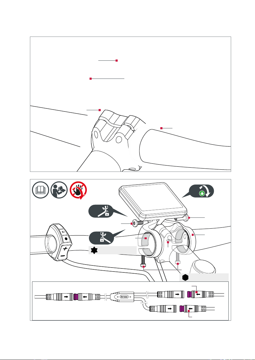
Brose Display Remote E41227
The Brose Display Remote E41227
control unit is intended for displaying
information relevant to cycling and for
controlling the drive unit of the Brose
Drive System.
∙The Brose Display Remote E41227
control unit is designed and intended
exclusively for use with a Brose Drive
System.
∙The Brose Display Remote E41227
control unit can be mounted on
the right or left side of the e-bike
handlebars.
∙Any other use is considered not to be
intended use.
Brose Display Central E41229
The Brose Display Central E41229
display unit is intended to be used
exclusively in combination with the
Brose Display Remote E41227 control
unit to display information relevant to
cycling and to control the drive unit of
the Brose Drive System.
∙The Brose Display Central E41229
display unit is designed and intended
for use with a Brose Drive System
only in combination with the Brose
Display Remote E41227 control unit.
∙The Brose Display Central E41229
display unit can only be mounted
centrally on the handlebars of the
e-bike.
∙Any other use is considered not to be
intended use.