manuals.online logo
Brands
  1. Home
  2. •
  3. Brands
  4. •
  5. Brute Force
  6. •
  7. Fitness Equipment
  8. •
  9. Brute Force RAPTOR User manual

Brute Force RAPTOR User manual

Multi-Functional
Leverage Trainer
Owner’s Manual
1
Content
Content -------------------------------------------------------------------- 1
Safety precautions ------------------------------------------------------- 2
Part List -------------------------------------------------------------------- 3
Assembly ------------------------------------------------------------------- 4-11
Maintenance --------------------------------------------------------------- 12
2
Safety Precautions
Safety First
Regardless of how enthusiastic you may be about getting on your equipment and
exercising, take the time to ensure that your safety is not jeopardized. A moment’s
lack of attention can result in an accident, as can failure to observe certain simple
safety precautions.
1. Read, study and understand the Owner’s Manual and all the warning labels on this
product. Furthermore, it is recommended to familiarize yourself and others with
the proper operation and workout recommendations for this product prior to use.
Some of this information can be obtained in this Owner’s Manual, as-well-as from
your local retailer.
2. It is imperative that you retain this Owner’s Manual and be sure all warning labels
are legible and intact. Replacement Owner’s Manuals and labels are available from
your local retailer.
3. It is recommended that another person assist you with the assembly of this unit.
4. Consult with your physician before beginning any exercise program.
5. Use proper discretion when children are present.
6. Frayed or worn cables can be dangerous and may cause injury. Periodically check
these cables for any indication of wear.
7. Keep hands, limbs, loose clothing and long hair well out of the way of moving
parts.
8. Do not attempt to lift more weight than you can control safely.
9. Inspect the machine for any sign of wear on parts, hardware becoming loose or
cracks on welds. If a problem is found do not use or allow the machine to be used
until the defective part is repaired or replaced.
10.You can use the WRENCH and the INNER HEX WRENCH to complete the
assembly.
3
Part List
Key
No.
Description Qty. Key
No.
Description Qty.
1
Base Frame
1
2
Side Base frame
2
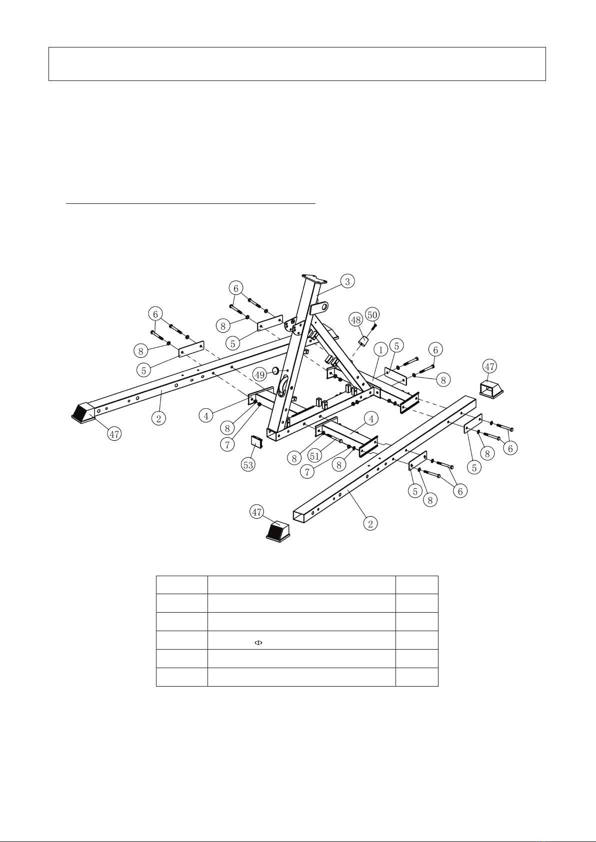
3 Big Stand Frame 1 4 Big Stand Frame Connector 2
5 Plate 5 6 Hex Bolt M10*90 27
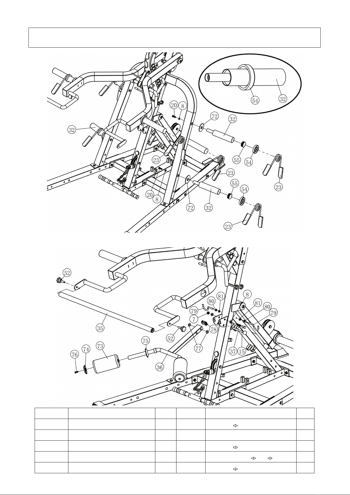
7 Nylon Lock Nut 10 51 8 Washer 10 104
9
Bending Tube(up)
1
1
1
1
1
1
1
1
1
1
1
1
1
1
1
1
1
1
1
1
1
1
1
1
1
1
1
1
1
1
1
1
10
Up Cross Tube
1
11 Climber Grips(L) 1 12 Climber Grips(R) 1
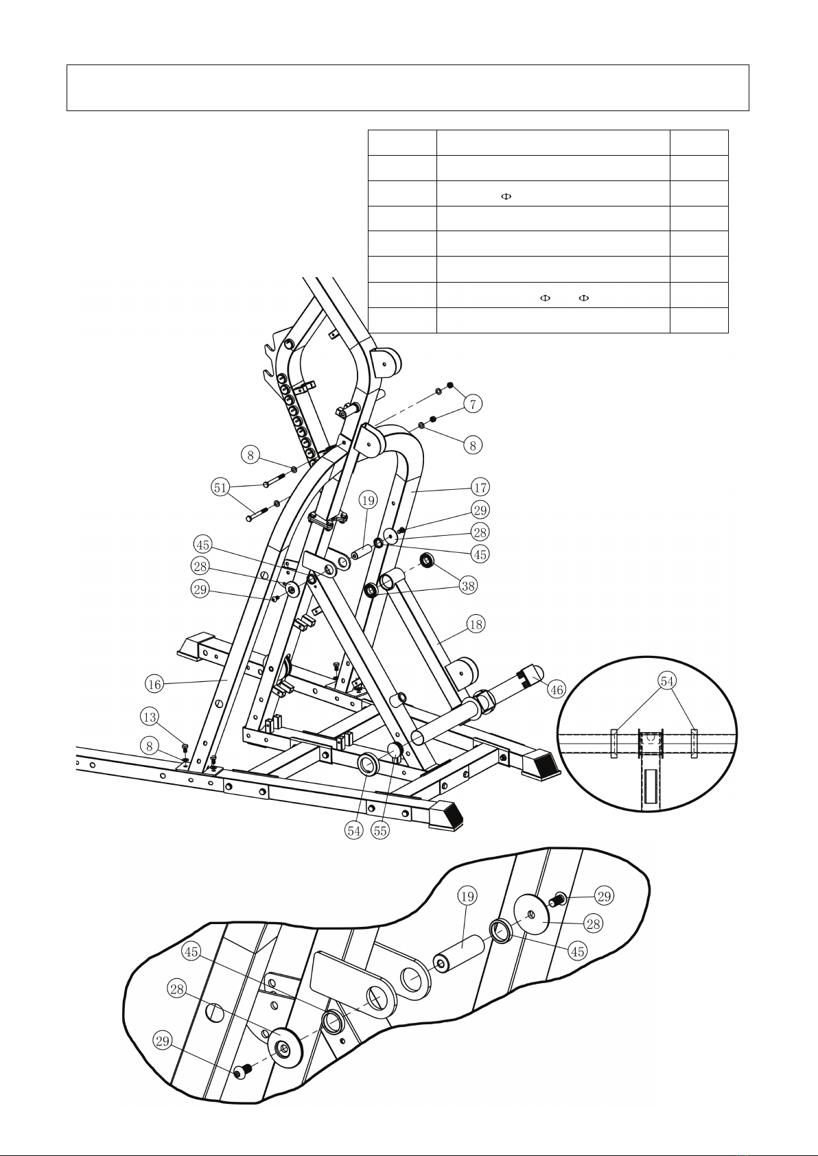
13 Hex Bolt M10*16 4 14 Sleeve 32*25*30 1
15 Hex Bolt M10*75 3 16 Support Tube(R) 1
17 Support Tube(L) 1 18 High Pull Barbell Welding 1
19 High Pull Connect Shaft 1
1
1
1
1
1
1
1
1
1
1
1
1
1
1
1
1
1
1
1
1
1
1
1
1
1
1
1
1
1
1
1
20 Hex Bolt M10*25 8
21 Hex Socket Head Bolt M10*40 4 22 Comfort Grip 28 2
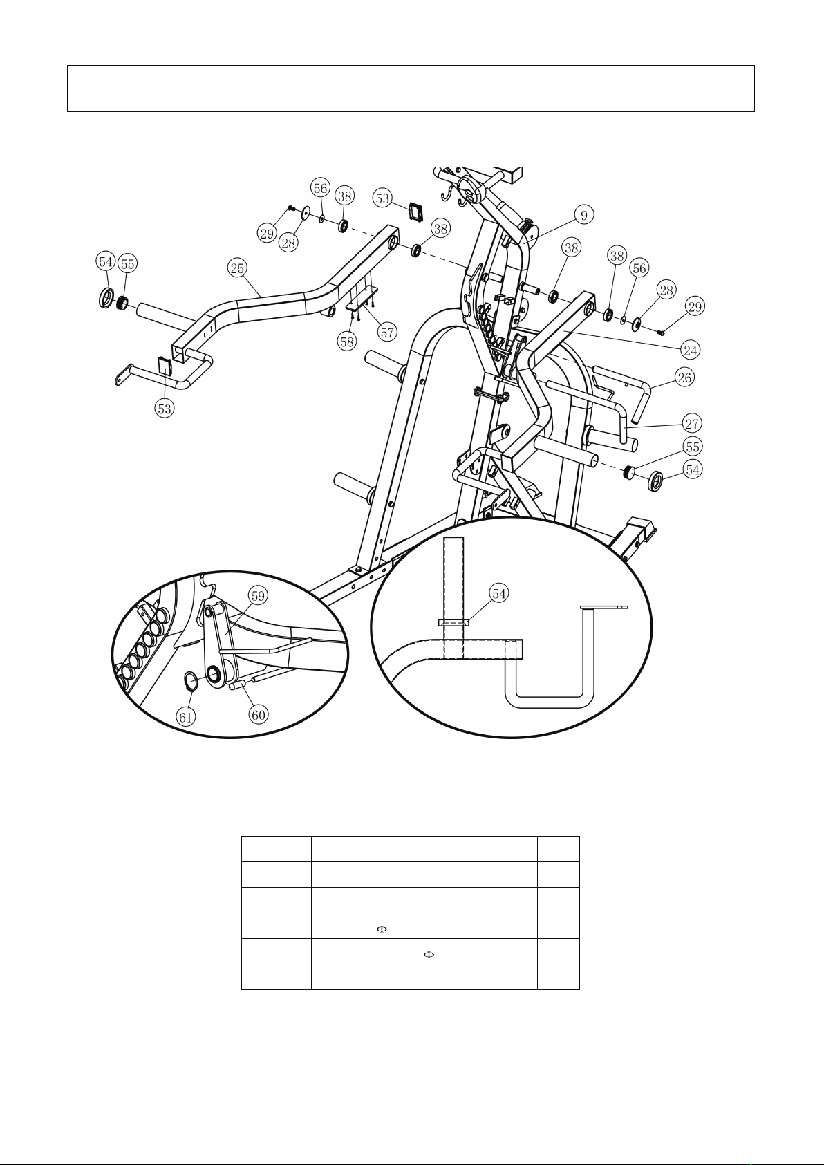
23 Spring Clip 8 24 Push Handle(L) 1
25 Push Handle(R) 1 26 Limit Rod 25 1
27 Double Push Safety Rod 25 1 28 Steel Cap 54 4
29 Hex Socket Head Bolt M10*20 4
1
1
1
1
1
1
1
1
1
1
1
1
1
1
1
1
1
1
1
1
1
1
1
1
1
1
1
1
1
1
1
30 High Pull Handle 1
31 Cable 1 32 Barbell Plate Inner Shaft 4
33 Coil Chain 2 34 Pulley 5
35 Connection Rod 1 36 Adjuster Tube 1
37 Ball Head Pin 1 38 Deep Groove Ball Bearings 6005 6
39 Decorate Shield 6
1
1
1
1
1
1
1
1
1
1
1
1
1
1
1
1
1
1
1
1
1
1
1
1
1
1
1
1
1
40 Rear Decorate Shield 2
41
Down Shield Plate
2
42
Up Shield Plate
2
43 Foot Board 1 44 L Shape Pin 4
45 Steel Bushing 32*25*7 2 46 Plug 60*60 1
47 Foot End Cap 4 48 Buffer 39 *41 1
49 Buffer 38 *7 1
1
1
1
1
1
1
1
1
1
1
1
1
1
1
1
1
1
1
1
1
1
1
1
1
50 Hex Socket Head Bolt M8*30 1
51
Hex Bolt M10*95
4
52
Screw Knob
2
53 Plug 70*50 1 54 Buffer 76*16 1
55 Round Plug 50 1 56 Washer 32*1
w76
2
57 Buffer 160*45 2 58 Tapping Screw 4.2*19 8
59 Hook Welding 1
1
1
1
1
1
1
1
1
1
1
1
1
1
1
1
1
1
1
1
1
60 Plastic Cap 10*36 1
61
Circlip 35
1
62
Hex Bolt M10*85
6
63 Hex Bolt M10*55 1 64 Plastic Cable Limiter 2
65 Plastic Bushing For Cable Limiter 22*6 2 66 Hex Bolt M10*45 2
67 Steel Bushing 16*23 4 68 Lat Pull Down Bar 1
69
Handlebar Tube
1
70
Comfort Grip 25
4
71 Snap Link 4 72 Washer 78*3
73 Foam Roller 2 74 Foam Roller Cap(small hole) 2
75 Foam Roller Cap(big hole) 2 76 Hex Socket Head Bolt M8*20 2
77 Nylon Washer 24* 10*2 2 78 Plug 50*25 1
79 Hook 2 80 Nut M8 2
81 Washer 8 24 82 Hex Socket Head Bolt M8*12 22
83
Hex Bolt M10*30
2
84
4
Assembly Instruction
Note:
1. Washer should be placed on both ends of all bolts (against the head of the bolt and against
the nut) unless otherwise specified in these instructions.
2. Hand tighten all bolts on initial assembly and finally tighten with the wrench once the entire
structure is erect.
3. Water or soap makes the assembly of foam easier.
4. Some parts may be pre-assembled at the factory.
5. Assembly requires the assistance of another person.
Step 1
Key No. Description Qty.
6 Hex Bolt M10*90 10
7 Nylon Lock Nut M10 12
8 Washer 10 24
50 Hex Socket Head Bolt M8*30 1
51 Hex Bolt M10*95 2
5
Assembly
Step 2
Key No. Description Qty.
7 Nylon Lock Nut M10 8
8 Washer 10 14
15 Hex Bolt M10*75 2
20 Hex Bolt M10*25 4
21 Hex Socket Head Bolt M10*40 4
6
Assembly
Step 3
Key No. Description Qty.
7 Nylon Lock Nut M10 2
8 Washer 10 8
13 Hex Bolt M10*16 4
29 Hex Socket Head Screw M10*20 2
38 Bearing 6005 2
45 Steel Bushing 32*25*7 2
51 Hex Bolt M10*95 2
7
Assembly
Step 4
Key No. Description Qty.
29 Hex Socket Head Bolt M10*20 2
38 Bearing 6005 4
56 Washer 32*1 2
58 Tapping Screw 4.2*19 8
61 Circlip 35 1
8
Assembly
Step 5
CABLE DIAGRAMS
Key No. Description Qty. Key No. Description Qty.
7 Nylon Lock Nut M10 7 8 Washer 10 10
33 Coil Chain 2 62 Hex Bolt M10*85 2
63 Hex Bolt M10*55 1 66 Hex Bolt M10*45 2
67 Steel Bushing 16*23 4 71 Snap Link 4
83 Hex Bolt M10*30 2
9
Assembly
Step 6
Step 7
Key No. Description Qty. Key No. Description Qty.
7 Nylon Lock Nut M10 8 Washer 10 6
15 Hex Bolt M10*75 1 20 Hex Bolt M10*25 4
37 Ball Head Pin 1 72 Washer 78*3 4
76 Hex Socket Head Bolt M8*20 2 77 Nylon Washer 24*10*2 2
80 Nut M8 2 81 Washer 8 2
10
Assembly
Step 8
Key No. Description Qty.
81 Washer 8 22
82 Hex Socket Head Bolt M8*12 22
11
Assembly
Step 9
Wrench to tighten all bolts and nuts.
The machine should now be fully assembled.
Please check that all bolts are tight and cables are seated correctly on all pulleys before
using.
Key No. Description Qty.
6 Hex Bolt M10*90 16
7 Nylon Lock Nut M10 20
8 Washer 10 40
62 Hex Bolt M10*85 4
12
Maintenance
Maintenance Information
1. Lubrication of all moving parts is essential to the longevity and optimal performance of your Machine.
Initial lubrication of some parts of your gym has been done at the factory.
Note: Do not use oil based lubricants as they will attract dust, dirt and grime, and will eventually gum up
and erode bushings and sealed bearings.
2. All pulleys and bushings should be checked regularly for signs of wear.
3. Check and adjust cable tension periodically as it will maintain proper anatomical function.
4. Periodically check all moving parts, upholstery and grips for signs of wear or damage. If there is a
problem or replacement part which is necessary, STOP USING THE EQUIPMENT and immediately
contact your local retailer. Replace parts using only genuine parts.
5. As needed, upholstery may be cleaned with a mild solution of soap and water. Regular use of a vinyl
treatment will add tothe life and appearance of your upholstery.
6. All chrome plated surfaces should be cleaned regularly to prolong the life and luster of the finish.
Wipe machine down with a damp cloth and dry thoroughly each day. At least once a week your
chrome equipment should be polished with a commercial grade or automotive type chrome polish.
7. When checking the bolts and nuts, be sure they are all fully fastened. If there is a bolt or nut that
continuously loosens obtain a replacement through your local retailer.
8. Check welds to be free of cracks.
9. Failure to perform routine maintenance could result in personal injury and/or equipment damage.
AUSTRALIA
WWW.RENOUFFITNESS.COM.AU

Other Brute Force Fitness Equipment manuals

Brute Force UX1 User manual

Brute Force

Brute Force UX1 User manual

Brute Force UX1 User manual

Brute Force

Brute Force UX1 User manual

Brute Force SUPA808-L User manual

Brute Force

Brute Force SUPA808-L User manual

Popular Fitness Equipment manuals by other brands

Star Trac eSpinner 7140 Troubleshooting

Star Trac

Star Trac eSpinner 7140 Troubleshooting

Tuff stuff SP-4402 Assembly manual

Tuff stuff

Tuff stuff SP-4402 Assembly manual

Life Gear 63100 owner's manual

Life Gear

Life Gear 63100 owner's manual

Tuff stuff CHL-610WS owner's manual

Tuff stuff

Tuff stuff CHL-610WS owner's manual

Activeforever Fluid Cycle XT E720 owner's manual

Activeforever

Activeforever Fluid Cycle XT E720 owner's manual

Life Fitness X15 Benutzerhandbuch

Life Fitness

Life Fitness X15 Benutzerhandbuch

BODYMAX CTX5 Assembly and operating instructions

BODYMAX

BODYMAX CTX5 Assembly and operating instructions

Lifepro TrimLite manual

Lifepro

Lifepro TrimLite manual

Life Gear Deluxe owner's manual

Life Gear

Life Gear Deluxe owner's manual

Life Fitness MJAXO parts manual

Life Fitness

Life Fitness MJAXO parts manual

FREE MOTION GZPL40320 owner's manual

FREE MOTION

FREE MOTION GZPL40320 owner's manual

Pro-Form PFBE19618.0 user manual

Pro-Form

Pro-Form PFBE19618.0 user manual

Pure Fun 9336GBP product manual

Pure Fun

Pure Fun 9336GBP product manual

Life Fitness CLUB Series ARM CURL Assembly instructions

Life Fitness

Life Fitness CLUB Series ARM CURL Assembly instructions

Pro-Form 325 CSX user manual

Pro-Form

Pro-Form 325 CSX user manual

FREE MOTION F218.0 owner's manual

FREE MOTION

FREE MOTION F218.0 owner's manual

Pro-Form CROSSTRAINER owner's manual

Pro-Form

Pro-Form CROSSTRAINER owner's manual

BODYMAX WB150 Assembly and operating instructions

BODYMAX

BODYMAX WB150 Assembly and operating instructions

manuals.online logo
manuals.online logoBrands
  • About & Mission
  • Contact us
  • Privacy Policy
  • Terms and Conditions

Copyright 2025 Manuals.Online. All Rights Reserved.