INDEX
Parts list
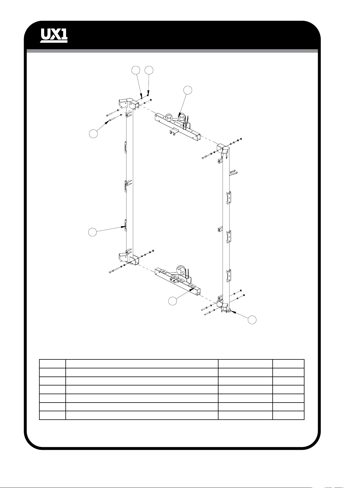
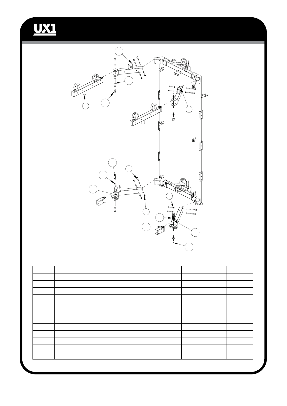
Assembly step 1
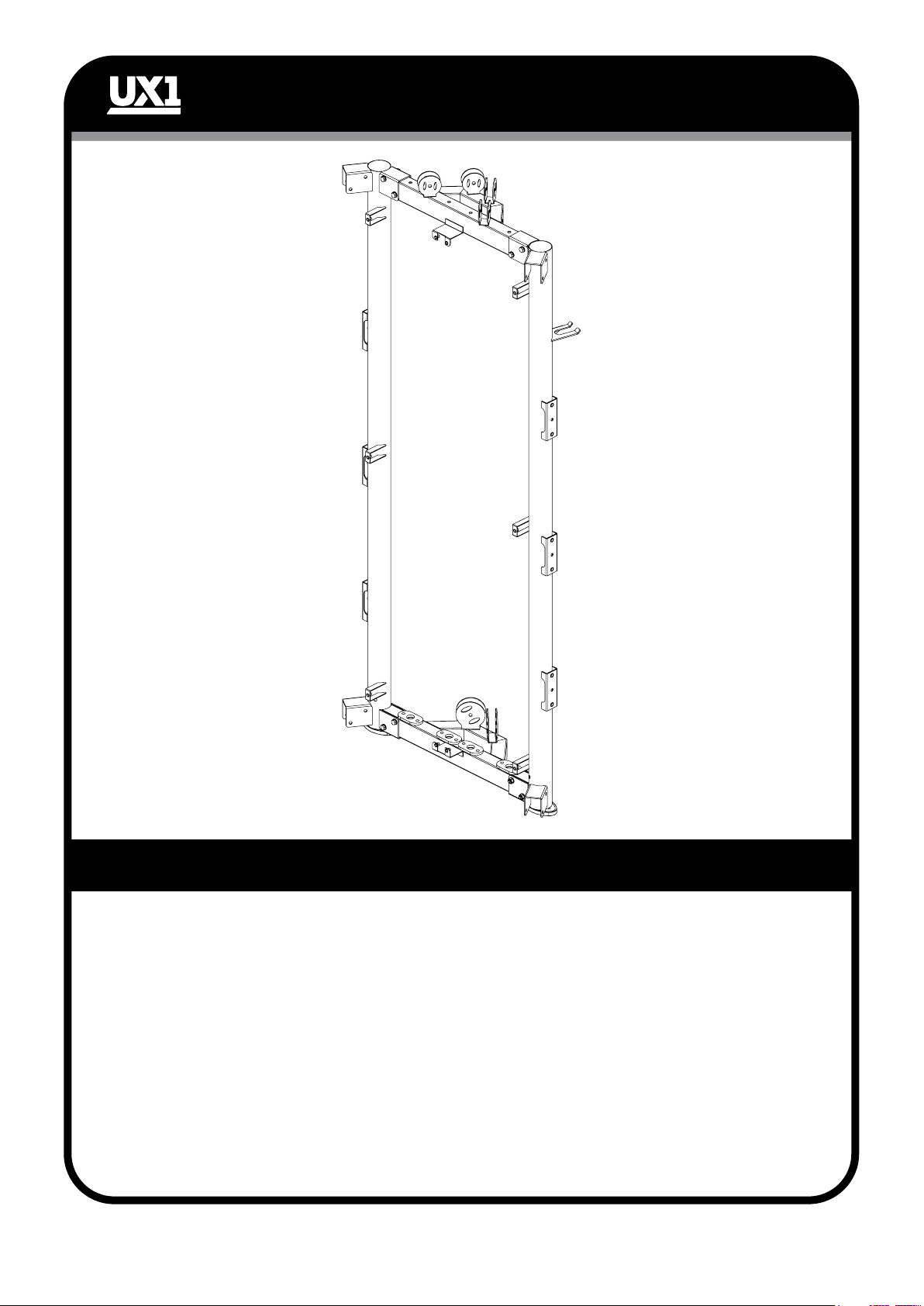
Assembly step 2
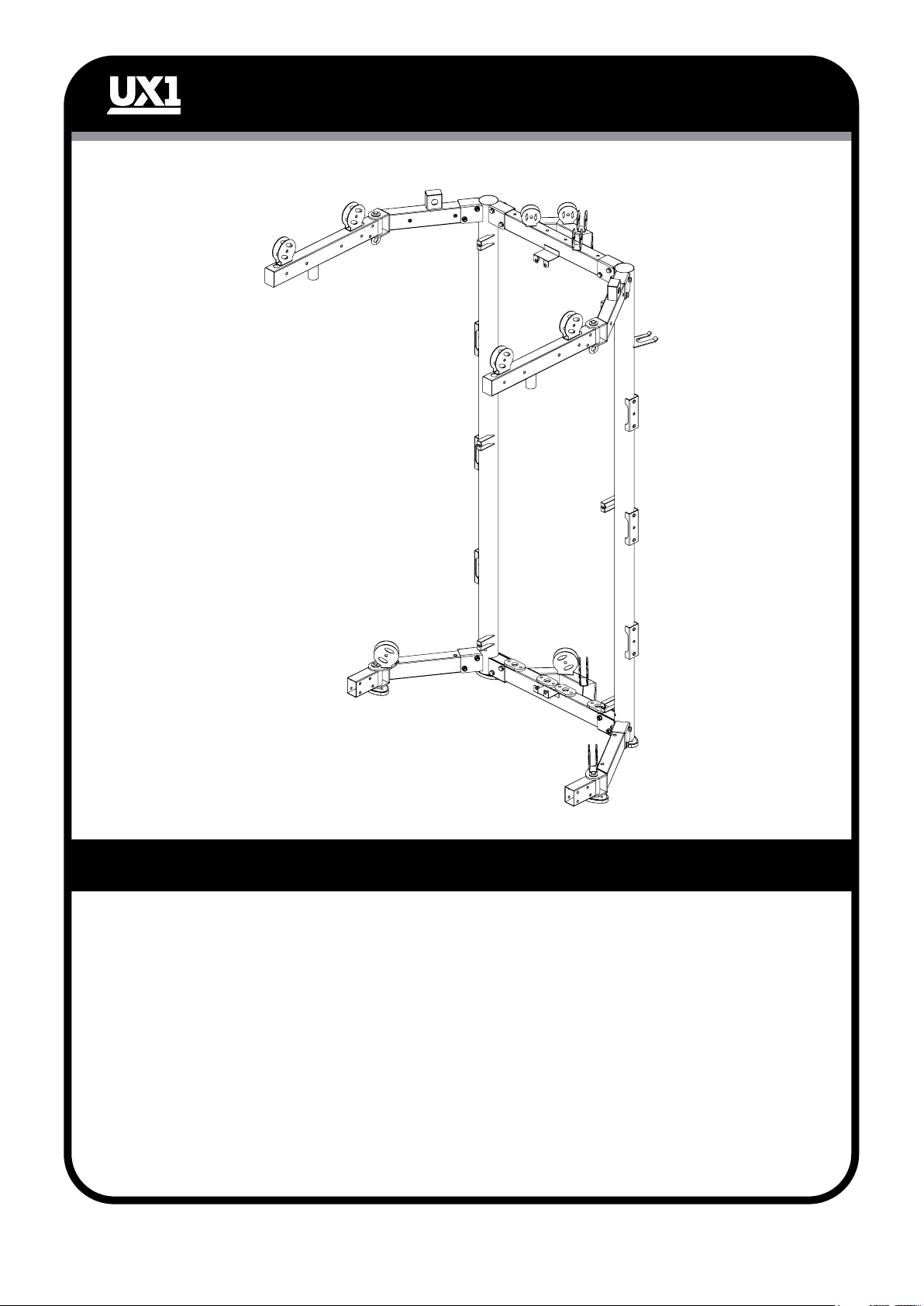
Assembly step 3
Assembly step 4
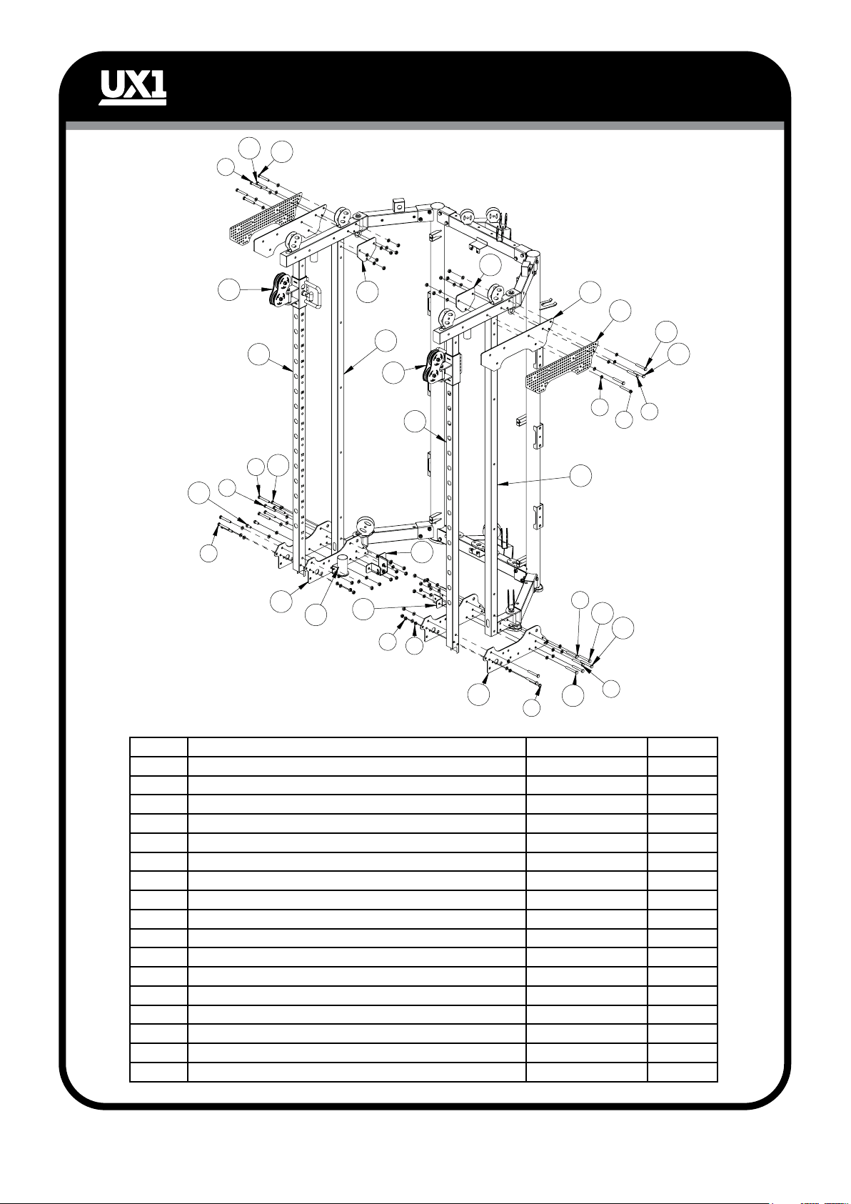
Assembly step 5
Assembly step 6
Assembly step 7
Assembly step 8
Assembly step 9
Assembly step 10
Assembly step 11
Additional Attachments
2 - 4
5 - 6
7 - 8
9 - 10
11 - 12
13 - 14
15 - 16
17 - 18
19 - 20
21 - 22
23 - 24
25 - 26
27
!! IMPORTANT !!
DO NOT FULLY TIGHTEN HARDWARE UNTIL COMPLETELY ASSEMBLED.
PLEASE NOTE: Some components may be pre-assembled.
YOU MUST FOLLOW THESE PRECAUTIONS TO AVOID INJURY. SERIOUS INJURY CAN
OCCUR ON THIS EQUIPMENT.
1. Before using, read all the warnings and precautionary instructions for the use of this machine. Use only for exercise
intended. DO NOT modify this machine.
2. Consult a physician prior to use.
3. Keep clothing and body parts free from all moving parts.
4. Fully inspect machine before use. DO NOT use if broken or damage. DO NOT attempt to repair. Notify
professional immediately.
5. Be certain that all securing and safety pins are completely inserted and tightened during use. Use only the pins
provided by the manufacturer. If unsure seek assistance.
6. Inspect all parts of the machine including cables and pulleys for wear and or damage prior to use. DO NOT
attempt to fix, seek professional assistance.
7. Children are not allowed near this machine. Teenagers need to be supervised.
8. This machine must be used and stored indoors in a dry and dust free environment. Not to be used or stored outside,
on a veranda, in an unlined shed or any other type of shelter.
9. IMPORTANT! When removing crown release pin (42) to fold machine, always hold the crown to avoid it from
dropping onto the user.
As we are continually evolving our products please note that some miner details in the manual
may differ from the product received.
- 1 -