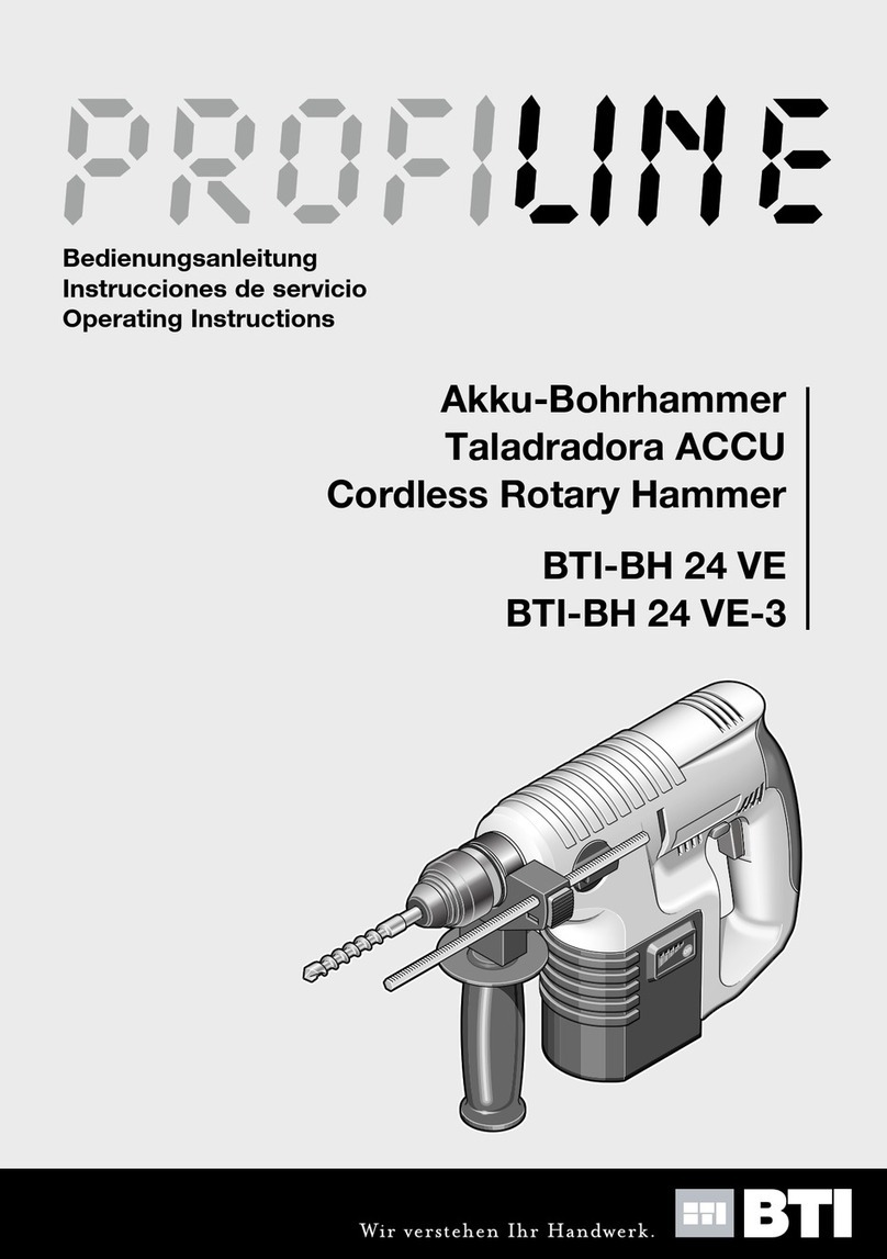
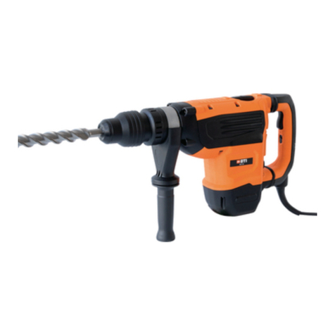
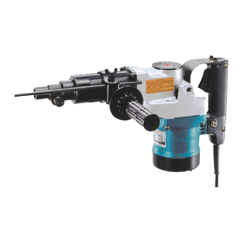
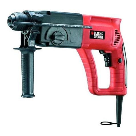
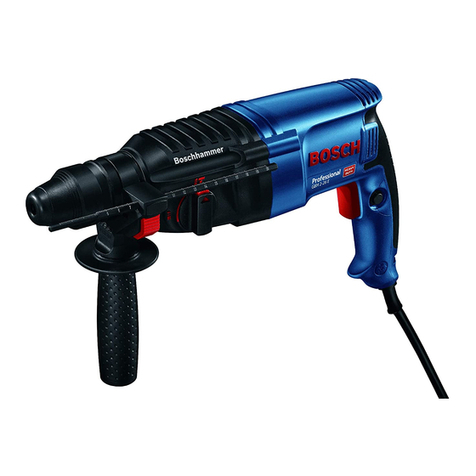
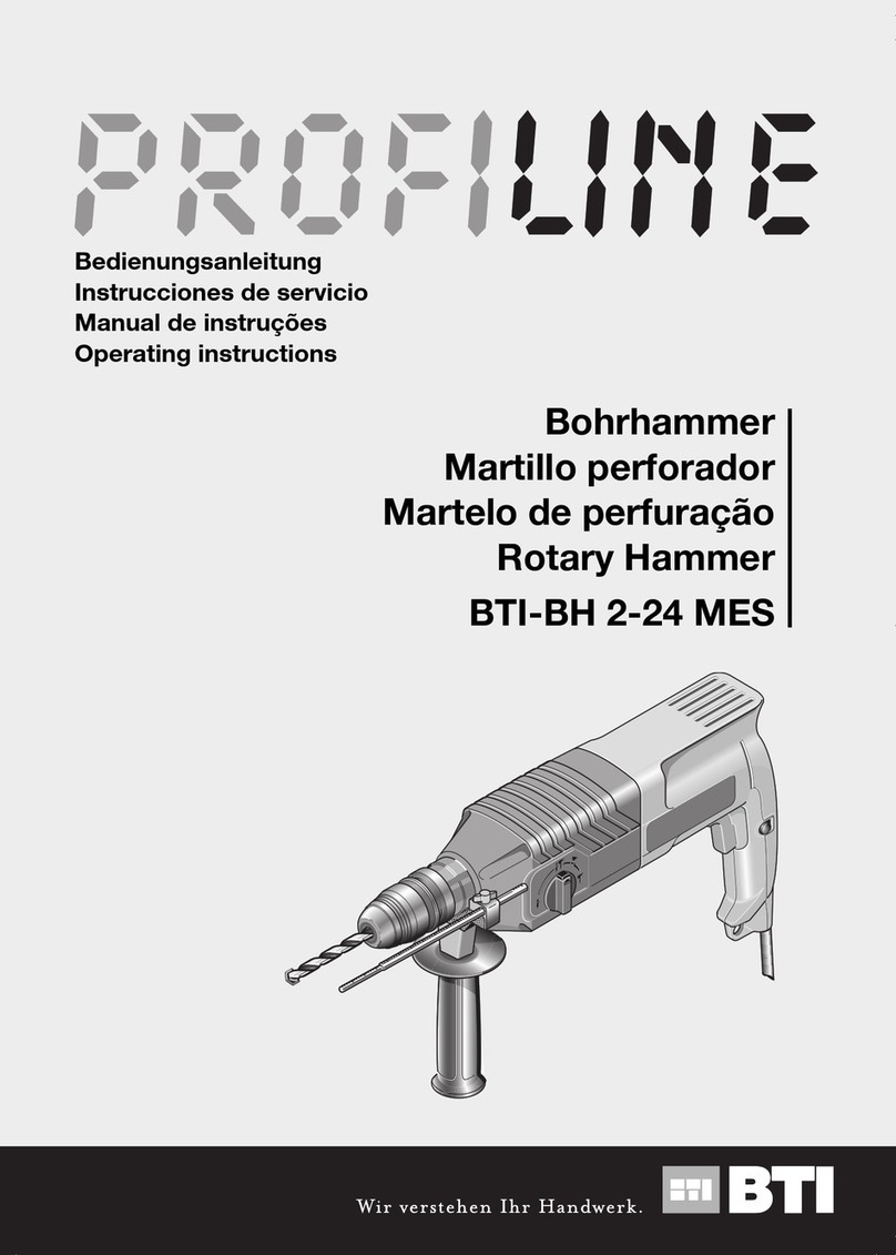
BTI Profiline BTI-BH 2-26 ME User manual

"OHRHAMMER
2OTARYª(AMMER
-ARTEAUªPERFORATEUR
ƠLjdžNjljNJǀǁǕƚLjǐLJƸDŽdž
"OORHAMER
-ARTELLOªPERFORATORE
-OTEKªUDAROWOOBROTOWY
-ARTELOªDEªPERFURAÎÍO
ǮȓȞȢȜȞȍȠȜȞ
-ARTILLOªPERFORADOR
"4)"(ªª-%ª
"4)"(ªª-%3
"EDIENUNGSANLEITUNG
/PERATINGªINSTRUCTIONS
)NSTRUCTIONSªDEMPLOI
ƫNjǂǂǐƻǀdždžƻƾƺǀǘDŽ
'EBRUIKSAANWIJZING
)STRUZIONIªDUSO
)NSTRUKCJAªOBSUGI
-ANUALªDEªINSTRUÎÜES
ǮȜșȪȕȜȏȍțȖȓȖțȟȠȞȡȚȓțȠȜȚ
)NSTRUCCIONESªDEªSERVICIO

BTI-BH 2-26 MES
BTI-BH 2-26 ME
34
5
7
8
9
10
11
12
13
14
1
26

A
14
B
15
17
318
5
16
C
6
a
b
D
19
E
3
F
5
a
b

M
27
3
5
L
t
22 23 24 25 26
I
12
13
t14
G
20 21
K
12
H
20 21

Deutsch–1
1 619 929 704 • (05.06) T
1 ALLGEMEINE SICHERHEITSHINWEISE
Sämtliche Anweisungen sind zu
lesen. Fehler bei der Einhaltung der
nachstehend aufgeführten Anwei-
sungen können elektrischen Schlag, Brand und/oder
schwere Verletzungen verursachen. Der nachfolgend
verwendete Begriff „Elektrowerkzeug“ bezieht sich auf
netzbetriebene Elektrowerkzeuge (mit Netzkabel) und
auf akkubetriebene Elektrowerkzeuge (ohne Netzka-
bel).
Bewahren Sie diese Anweisungen gut auf.
1) Arbeitsplatz
a) Halten Sie Ihren Arbeitsbereich sauber und
aufgeräumt. Unordnung und unbeleuchtete Ar-
beitsbereiche können zu Unfällen führen.
b) Arbeiten Sie mit dem Gerät nicht in
explosionsgefährdeter Umgebung, in der
sich brennbare Flüssigkeiten, Gase oder
Stäube befinden. Elektrowerkzeuge erzeugen
Funken, die den Staub oder die Dämpfe entzün-
den können.
c) Halten Sie Kinder und andere Personen
während der Benutzung des Elektrowerk-
zeugs fern. Bei Ablenkung können Sie die Kon-
trolle über das Gerät verlieren.
2) Elektrische Sicherheit
a) Der Anschlussstecker des Gerätes muss in
die Steckdose passen. Der Stecker darf in
keiner Weise verändert werden. Verwenden
Sie keine Adapterstecker gemeinsam mit
schutzgeerdeten Geräten. Unveränderte Ste-
cker und passende Steckdosen verringern das
Risiko eines elektrischen Schlages.
b) Vermeiden Sie Körperkontakt mit geerde-
ten Oberflächen wie Rohren, Heizungen,
Herden und Kühlschränken. Es besteht ein
erhöhtes Risiko durch elektrischen Schlag, wenn
Ihr Körper geerdet ist.
c) Halten Sie das Gerät von Regen oder Nässe
fern. Das Eindringen von Wasser in ein Elektro-
gerät erhöht das Risiko eines elektrischen Schla-
ges.
d) Zweckentfremden Sie das Kabel nicht, um
das Gerät zu tragen, aufzuhängen oder um
den Stecker aus der Steckdose zu ziehen.
Halten Sie das Kabel fern von Hitze, Öl,
scharfen Kanten oder sich bewegenden
Geräteteilen. Beschädigte oder verwickelte
Kabel erhöhen das Risiko eines elektrischen
Schlages.
e) Wenn Sie mit einem Elektrowerkzeug im
Freien arbeiten, verwenden Sie nur Verlän-
gerungskabel, die auch für den Außenbe-
reich zugelassen sind. Die Anwendung eines
für den Außenbereich geeigneten Verlänge-
rungskabels verringert das Risiko eines elektri-
schen Schlages.
3) Sicherheit von Personen
a) Seien Sie aufmerksam, achten Sie darauf,
was Sie tun und gehen Sie mit Vernunft an
die Arbeit mit einem Elektrowerkzeug. Be-
nutzen Sie das Gerät nicht, wenn Sie müde
sind oder unter dem Einfluss von Drogen,
Alkohol oder Medikamenten stehen. Ein Mo-
ment der Unachtsamkeit bei dem Gebrauch des
Gerätes kann zu ernsthaften Verletzungen füh-
ren.
b) Tragen Sie persönliche Schutzausrüstung
und immer eine Schutzbrille. Das Tragen per-
sönlicher Schutzausrüstung, wie Staubmaske,
rutschfeste Sicherheitsschuhe, Schutzhelm oder
Gehörschutz, je nach Art und Einsatz des Elek-
trowerkzeuges, verringert das Risiko von Verlet-
zungen.
c) Vermeiden Sie eine unbeabsichtigte Inbe-
triebnahme. Vergewissern Sie sich, dass
das Elektrowerkzeug ausgeschaltet ist, be-
vor Sie den Stecker in die Steckdose ste-
cken. Wenn Sie beim Tragen des Gerätes den
Finger am Schalter haben oder das Gerät einge-
schaltet an die Stromversorgung anschließen,
kann dies zu Unfällen führen.
d) Entfernen Sie Einstellwerkzeuge oder
Schraubenschlüssel, bevor Sie das Gerät
einschalten. Ein Werkzeug oder Schlüssel, der
sich in einem drehenden Geräteteil befindet,
kann zu Verletzungen führen.
e) Überschätzen Sie sich nicht. Sorgen Sie für
einen sicheren Stand und halten Sie jeder-
zeit das Gleichgewicht. Dadurch können Sie
das Gerät in unerwarteten Situationen besser
kontrollieren.
f) Tragen Sie geeignete Kleidung. Tragen Sie
keine weite Kleidung oder Schmuck. Halten
Sie Haare, Kleidung und Handschuhe fern
von sich bewegenden Teilen. Lockere Klei-
dung, Schmuck oder lange Haare können von
sich bewegenden Teilen erfasst werden.
g) Wenn Staubabsaug- und -auffangein-
richtungen montiert werden können,
vergewissern Sie sich, dass diese ange-
schlossen sind und richtig verwendet wer-
den. Das Verwenden dieser Einrichtungen ver-
ringert die Gefährdungen durch Staub.
4) Sorgfältiger Umgang mit und Gebrauch von
Elektrowerkzeugen
a) Überlasten Sie das Gerät nicht. Verwenden
Sie für Ihre Arbeit das dafür bestimmte
Elektrowerkzeug. Mit dem passenden Elektro-
werkzeug arbeiten Sie besser und sicherer im
angegebenen Leistungsbereich.
Deutsch–2
1 619 929 704 • (05.06) T
b) Benutzen Sie kein Elektrowerkzeug, des-
sen Schalter defekt ist. Ein Elektrowerkzeug,
das sich nicht mehr ein- oder ausschalten lässt,
ist gefährlich und muss repariert werden.
c) Ziehen Sie den Stecker aus der Steckdose,
bevor Sie Geräteeinstellungen vornehmen,
Zubehörteile wechseln oder das Gerät
weglegen. Diese Vorsichtsmaßnahme verhin-
dert den unbeabsichtigten Start des Gerätes.
d) Bewahren Sie unbenutzte Elektrowerkzeu-
ge außerhalb der Reichweite von Kindern
auf. Lassen Sie Personen das Gerät nicht
benutzen, die mit diesem nicht vertraut sind
oder diese Anweisungen nicht gelesen ha-
ben. Elektrowerkzeuge sind gefährlich, wenn sie
von unerfahrenen Personen benutzt werden.
e) Pflegen Sie das Gerät mit Sorgfalt. Kontrol-
lieren Sie, ob bewegliche Geräteteile ein-
wandfrei funktionieren und nicht klemmen,
ob Teile gebrochen oder so beschädigt
sind, dass die Funktion des Gerätes beein-
trächtigt ist. Lassen Sie beschädigte Teile
vor dem Einsatz des Gerätes reparieren.
Viele Unfälle haben ihre Ursache in schlecht ge-
warteten Elektrowerkzeugen.
f) Halten Sie Schneidwerkzeuge scharf und
sauber. Sorgfältig gepflegte Schneidwerkzeuge
mit scharfen Schneidkanten verklemmen sich
weniger und sind leichter zu führen.
g) Verwenden Sie Elektrowerkzeug, Zubehör,
Einsatzwerkzeuge usw. entsprechend die-
sen Anweisungen und so, wie es für diesen
speziellen Gerätetyp vorgeschrieben ist.
Berücksichtigen Sie dabei die Arbeitsbe-
dingungen und die auszuführende
Tätigkeit. Der Gebrauch von Elektrowerkzeu-
gen für andere als die vorgesehenen Anwendun-
gen kann zu gefährlichen Situationen führen.
5) Service
a) Lassen Sie Ihr Gerät nur von qualifiziertem
Fachpersonal und nur mit Original-Ersatz-
teilen reparieren. Damit wird sichergestellt,
dass die Sicherheit des Gerätes erhalten bleibt.
2 GERÄTESPEZIFISCHE SICHERHEITSHINWEISE
Tragen Sie Gehörschutz. Die Einwirkung von Lärm
kann Gehörverlust bewirken.
Treffen Sie Schutzmaßnahmen, wenn beim Ar-
beiten gesundheitsschädliche, brennbare oder
explosive Stäube entstehen können. Zum Beispiel:
Manche Stäube gelten als krebserregend. Verwenden
Sie eine Staub-/Späneabsaugung und tragen Sie eine
Staubschutzmaske.
Halten Sie Ihren Arbeitsplatz sauber. Materialmi-
schungen sind besonders gefährlich. Leichtmetall-
staub kann brennen oder explodieren.
Benutzen Sie das Gerät nicht mit beschädigtem
Kabel. Berühren Sie das beschädigte Kabel nicht
und ziehen Sie den Netzstecker, wenn das Kabel
während des Arbeitens beschädigt wird. Beschä-
digte Kabel erhöhen das Risiko eines elektrischen
Schlages.
Schließen Sie Geräte, die im Freien verwendet
werden, über einen Fehlerstrom(FI)-Schutz-
schalter an.
Verwenden Sie geeignete Suchgeräte, um ver-
borgene Versorgungsleitungen aufzuspüren,
oder ziehen Sie die örtliche Versorgungsgesell-
schaft hinzu. Kontakt mit Elektroleitungen kann zu
Feuer und elektrischem Schlag führen. Beschädigung
einer Gasleitung kann zur Explosion führen. Eindringen
in eine Wasserleitung verursacht Sachbeschädigung
oder kann einen elektrischen Schlag verursachen.
Benutzen Sie die mit dem Elektrowerkzeug mit-
gelieferten Zusatzgriffe. Der Verlust der Kontrolle
über die Maschine kann zu Verletzungen führen.
Sichern Sie das Werkstück. Ein mit Spannvorrich-
tungen oder Schraubstock festgehaltenes Werkstück
ist sicherer gehalten als mit Ihrer Hand.
Bearbeiten Sie kein asbesthaltiges Material. As-
best gilt als krebserregend.
Halten Sie das Gerät beim Arbeiten fest mit bei-
den Händen und sorgen Sie für einen sicheren
Stand. Das Gerät wird mit zwei Händen sicherer ge-
führt.
Warten Sie, bis das Gerät zum Stillstand gekom-
men ist, bevor Sie es ablegen. Das Einsatzwerk-
zeug kann sich verhaken und zum Verlust der Kontrol-
le über das Gerät führen.
Überlastkupplung
Klemmt oder hakt das Einsatzwerkzeug, wird der An-
trieb zur Bohrspindel unterbrochen. Halten Sie, we-
gen der dabei auftretenden Kräfte, das Elektrowerk-
zeug immer mit beiden Händen gut fest und
nehmen Sie einen festen Stand ein.

Deutsch–3
1 619 929 704 • (05.06) T
3 FUNKTIONSBESCHREIBUNG
Sämtliche Anweisungen sind zu le-
sen. Fehler bei der Einhaltung der
nachstehend aufgeführten Anweisun-
gen können elektrischen Schlag, Brand
und/oder schwere Verletzungen verur-
sachen.
BEWAHREN SIE DIESE ANWEISUNGEN GUT
AUF.
Bestimmungsgemäßer Gebrauch
Das Gerät ist bestimmt zum Hammerbohren in Beton,
Ziegel und Gestein sowie für leichte Meißelarbeiten. Es
ist ebenso geeignet zum Bohren ohne Schlag in Holz,
Metall, Keramik und Kunststoff.
Geräte mit elektronischer Regelung und Rechts-/
Linkslauf sind auch geeignet zum Schrauben und Ge-
windeschneiden.
Geräusch-/Vibrationsinformation
Messwerte ermittelt entsprechend EN 60745.
Der A-bewertete Geräuschpegel des Gerätes beträgt
typischerweise:
Schalldruckpegel 91 dB(A);
Schallleistungspegel 102 dB(A).
Messunsicherheit K = 3 dB.
Gehörschutz tragen!
Die bewertete Beschleunigung beträgt typischerweise
12 m/s2.
Konformitätserklärung
Wir erklären in alleiniger Verantwortung, dass dieses
Produkt mit den folgenden Normen oder normativen
Dokumenten übereinstimmt:
EN 60745 gemäß den Bestimmungen der Richtlinien
89/336/EWG, 98/37/EG.
Ulrich Delz Günter Hub
BTI Befestigungstechnik Gmbh & Co. KG, 74653 Ingelfingen
Geräteelemente
Die Nummerierung der Geräteelemente bezieht sich
auf die Darstellung des Gerätes auf der Grafikseite.
1Schnellspann-Wechselbohrfutter
(BTI-BH 2-26 MES)
2SDS-plus-Wechselbohrfutter (BTI-BH 2-26 MES)
3Werkzeugaufnahme (SDS-plus)
4Staubschutzkappe
5Verriegelungshülse
6Wechselbohrfutter-Verriegelungsring
(BTI-BH 2-26 MES)
7Rechts-Linkslauf-Schalter
8Feststellknopf
9Ein-Aus-Schalter mit Gasgebefunktion
10 Entriegelungsknopf
11 Betriebsarten-Wahlschalter
12 Taste am Zusatzgriff
13 Tiefenanschlag
14 Zusatzgriff
15 Schraube für Bohrfutter*
16 Bohrfutter*
17 SDS-plus-Aufnahmeschaft für Bohrfutter*
18 Bohrfutter montiert*
19 Bohrfutteraufnahme (BTI-BH 2-26 MES)
20 Vordere Hülse des Schnellspann-Wechselbohr-
futters (BTI-BH 2-26 MES)
21 Haltering des Schnellspann-Wechselbohrfutters
(BTI-BH 2-26 MES)
22 Klemmschraube Saugfix*
23 Tiefenanschlag Saugfix*
24 Teleskoprohr Saugfix*
25 Flügelschraube Saugfix*
26 Führungsrohr Saugfix*
27 Universalhalter für Schrauberbits*
* Abgebildetes oder beschriebenes Zubehör gehört teil-
weise nicht zum Lieferumfang.

Deutsch–4
1 619 929 704 • (05.06) T
Gerätekennwerte
4 BETRIEB
Zusatzgriff (siehe Bild )
Verwenden Sie Ihr Gerät nur mit dem Zusatzgriff 14.
Sie können den Zusatzgriff 14 beliebig schwenken, um
eine sichere und ermüdungsarme Arbeitshaltung zu
erreichen.
Lösen Sie den Zusatzgriff 14 entgegen dem Uhrzei-
gersinn und schwenken Sie ihn in die gewünschte Po-
sition. Achten Sie darauf, dass das Spannband des
Zusatzgriffs in der dafür vorgesehenen Nut des Ge-
häuses liegt.
Danach drehen Sie den Zusatzgriff 14 im Uhrzeiger-
sinn wieder fest.
Bohrfutter und Werkzeuge
auswählen
Zum Hammerbohren und Meißeln benötigen Sie SDS-
plus-Werkzeuge, die in ein SDS-plus-Bohrfutter einge-
setzt werden.
Zum Bohren in Stahl oder Holz, zum Schrauben und
Gewindeschneiden werden Werkzeuge ohne SDS-
plus (z.B. Bohrer mit zylindrischem Schaft) verwendet.
Für diese Werkzeuge benötigen Sie ein Schnellspann-
oder ein Zahnkranzbohrfutter.
Verwenden Sie Werkzeuge ohne SDS-plus nicht
zum Hammerbohren oder Meißeln! Werkzeuge
ohne SDS-plus und ihr Bohrfutter werden beim Ham-
merbohren und Meißeln beschädigt.
BTI-BH 2-26 MES: Das SDS-plus-Wechselbohrfutter
kann leicht gegen das mitgelieferte Schnellspann-
Wechselbohrfutter ausgetauscht werden.
Bohrhammer BTI-BH 2-26 ME BTI-BH 2-26 MES
Artikelnummer 9001329 9001330
Drehzahlsteuerung ●●
Drehstopp ● ●
Rechts-/Linkslauf ●●
Wechselbohrfutter – ●
Nennaufnahmeleistung [W] 800 800
Schlagzahl bei Nenndrehzahl [min-1] 0 ... 4000 0 ... 4000
Einzelschlagstärke [J] 3,0 3,0
Nenndrehzahl
Rechtslauf
Linkslauf
[min-1]
[min-1]
0 ... 900
0 ... 900
0 ... 900
0 ... 900
Leerlaufdrehzahl [min-1] 1300 1300
Werkzeugaufnahme SDS-plus ● ●
Ø Spindelhals [mm] 50 50
Bohrdurchmesser (max.):
Mauerwerk (Hohlbohrkrone)
Beton
Holz
Stahl
[mm]
[mm]
[mm]
[mm]
68
26
30
13
68
26
30
13
Gewicht entsprechend EPTA-Procedure 01/2003 [kg] 2,7 2,9
Schutzklasse / II / II
A

Deutsch–5
1 619 929 704 • (05.06) T
Bohrfutter einsetzen/wechseln
BTI-BH 2-26 ME
Bohrfutter für Arbeiten mit Werkzeugen ohne
SDS-plus einsetzen (siehe Bild )
Um mit Werkzeugen ohne SDS-plus (z.B. Bohrer mit
zylindrischem Schaft) arbeiten zu können, muss ein
geeignetes Bohrfutter eingesetzt werden.
Schrauben Sie den SDS-plus-Aufnahmeschaft 17 (Zu-
behör) in ein Zahnkranz-Bohrfutter 16. Sichern Sie das
Bohrfutter mit der Schraube 15.
Reinigen Sie den Aufnahmeschaft vor dem Einsetzen,
und fetten Sie das Einsteckende leicht ein.
Setzen Sie das zusammengebaute Bohrfutter 18 mit
dem Aufnahmeschaft drehend in die Werkzeugauf-
nahme 3ein, bis es einrastet.
Der Aufnahmeschaft verriegelt sich selbsttätig. Prüfen
Sie die Verriegelung durch Ziehen am Bohrfutter.
Bohrfutter entnehmen
Zum Entnehmen des Bohrfutters 18 ziehen Sie die
Verriegelungshülse 5nach hinten, halten Sie sie in die-
ser Position fest, und entnehmen Sie das Bohrfutter
aus der Werkzeugaufnahme.
BTI-BH 2-26 MES
Wechselbohrfutter abnehmen (siehe Bild )
Ziehen Sie den Wechselbohrfutter-Verriegelungsring 6
nach hinten (a), halten Sie ihn in dieser Position fest
und entnehmen Sie das Wechselbohrfutter aus der
Bohrfutteraufnahme (b).
Schützen Sie das Wechselbohrfutter nach dem Ab-
nehmen vor Verschmutzung.
Wechselbohrfutter aufsetzen (siehe Bild )
Reinigen Sie das Wechselbohrfutter vor dem Einset-
zen und fetten Sie das Einsteckende leicht ein.
Umgreifen Sie das Wechselbohrfutter mit der ganzen
Hand. Schieben Sie das Wechselbohrfutter drehend
auf die Bohrfutteraufnahme 19, bis Sie ein deutliches
Einrastgeräusch hören.
Das Wechselbohrfutter verriegelt sich selbsttätig. Prü-
fen Sie die Verriegelung durch Ziehen am Wechsel-
bohrfutter.
Werkzeug einsetzen/wechseln
Achten Sie beim Wechseln der Werkzeuge dar-
auf, dass die Staubschutzkappe 4 nicht beschä-
digt wird.
SDS-plus-Werkzeuge
Das SDS-plus-Werkzeug ist systembedingt frei be-
weglich. Dadurch entsteht beim Leerlauf eine Rund-
laufabweichung, die sich beim Bohren selbsttätig zen-
triert. Dies hat keine Auswirkungen auf die Genauigkeit
des Bohrlochs.
SDS-plus-Werkzeuge einsetzen (siehe Bild )
BTI-BH 2-26 MES: Setzen Sie das SDS-plus-Wech-
selbohrfutter 2auf (siehe Wechselbohrfutter aufset-
zen).
Reinigen Sie das Werkzeug vor dem Einsetzen, und
fetten Sie das Einsteckende leicht ein.
Schieben Sie das Werkzeug drehend in die Werkzeug-
aufnahme 3ein, bis es einrastet.
Das Werkzeug verriegelt sich selbsttätig. Prüfen Sie
die Verriegelung durch Ziehen am Werkzeug.
SDS-plus-Werkzeuge entnehmen (siehe Bild )
Ziehen Sie die Verriegelungshülse 5nach hinten (a),
halten Sie sie in dieser Position fest und entnehmen
Sie das Werkzeug aus der Werkzeugaufnahme (b).
Werkzeuge ohne SDS-plus (BTI-BH 2-26 ME)
Verwenden Sie Werkzeuge ohne SDS-plus nicht
zum Hammerbohren oder Meißeln! Werkzeuge
ohne SDS-plus und ihr Bohrfutter werden beim Ham-
merbohren und Meißeln beschädigt.
Werkzeug einsetzen
Setzen Sie ein Zahnkranz-Bohrfutter 18 (Zubehör) ein
(siehe Bohrfutter für Arbeiten mit Werkzeugen ohne
SDS-plus einsetzen).
Drehen Sie die Hülse des Zahnkranz-Bohrfutters ent-
gegen dem Uhrzeigersinn, bis die Werkzeugaufnahme
weit genug geöffnet ist. Setzen Sie das Werkzeug in
die Mitte der Werkzeugaufnahme ein und spannen Sie
es mit einem Bohrfutterschlüssel gleichmäßig in allen
drei Bohrungen.
Werkzeug entnehmen
Drehen Sie die Hülse des Zahnkranz-Bohrfutters mit
Hilfe des Bohrfutterschlüssels entgegen dem Uhrzei-
gersinn, bis das Werkzeug aus der Werkzeugaufnah-
me entnommen werden kann.
B
C
D
E
F

Deutsch–6
1 619 929 704 • (05.06) T
Werkzeuge ohne SDS-plus (BTI-BH 2-26 MES)
Verwenden Sie Werkzeuge ohne SDS-plus nicht
zum Hammerbohren oder Meißeln! Werkzeuge
ohne SDS-plus und ihr Bohrfutter werden beim Ham-
merbohren und Meißeln beschädigt.
Werkzeug einsetzen (siehe Bild )
Setzen Sie das Schnellspann-Wechselbohrfutter 1auf
(siehe Wechselbohrfutter aufsetzen).
Halten Sie den Haltering 21 des Schnellspann-Wech-
selbohrfutters fest. Öffnen Sie die Werkzeugaufnahme
3durch Drehen der vorderen Hülse 20 so weit, bis das
Werkzeug eingesetzt werden kann.
Halten Sie den Haltering 21 fest und drehen Sie die
vordere Hülse 20 kräftig in Pfeilrichtung, bis deutliche
Ratschengeräusche zu hören sind.
Prüfen Sie den festen Sitz durch Ziehen am Werkzeug.
Hinweis: Nach dem Öffnen der Werkzeugaufnahme
bis zum Anschlag kann beim nachfolgenden Schließen
das funktionsbedingte Ratschengeräusch hörbar sein,
und die Werkzeugaufnahme schließt nicht.
Drehen Sie in diesem Fall die vordere Hülse 20 einmal
entgegen der Pfeilrichtung. Die Werkzeugaufnahme
kann dann geschlossen werden.
Werkzeug entnehmen (siehe Bild )
Halten Sie den Haltering 21 des Schnellspann-Wech-
selbohrfutters fest. Öffnen Sie die Werkzeugaufnahme
durch Drehen der vorderen Hülse 20 in Pfeilrichtung,
bis das Werkzeug entnommen werden kann.
Bohrtiefe einstellen (siehe Bild )
Mit dem Tiefenanschlag 13 kann die gewünschte
Bohrtiefe tfestgelegt werden.
Drücken Sie die Taste 12 des Zusatzgriffs und setzen
Sie den Tiefenanschlag so in den Zusatzgriff 14 ein,
dass die geriffelte Seite des Tiefenanschlags nach un-
ten zeigt.
Schieben Sie das SDS-plus-Werkzeug bis zum An-
schlag in die Werkzeugaufnahme 3. Die Beweglichkeit
des SDS-Werkzeugs kann sonst zu falscher Einstel-
lung der Bohrtiefe führen.
Ziehen Sie den Tiefenanschlag so weit heraus, dass
der Abstand zwischen der Spitze des Bohrers und der
Spitze des Tiefenanschlags der gewünschten Bohr-
tiefe tentspricht.
Staubabsaugung mit Saugfix
(Zubehör)
Saugfix montieren (siehe Bild )
Für die Staubabsaugung wird ein Saugfix (Zubehör)
benötigt. Beim Bohren federt der Saugfix zurück, so
dass der Saugfix-Kopf immer dicht am Untergrund ge-
halten wird.
Drücken Sie die Taste 12 des Zusatzgriffs und entneh-
men Sie den Tiefenanschlag 13. Drücken Sie die Taste
12 erneut und setzen Sie den Saugfix von vorn in den
Zusatzgriff 14 ein.
Schließen Sie einen Absaugschlauch (Ø 19 mm, Zu-
behör) an die Absaugöffnung des Saugfix an.
Der Staubsauger muss für den zu bearbeitenden
Werkstoff geeignet sein.
Beim Absaugen von besonders gesundheitsgefähr-
denden, krebserzeugenden, trockenen Stäuben ist ein
Spezialsauger zu verwenden.
In Deutschland werden für Holzstäube auf Grund
TRGS 553 geprüfte Absaugeinrichtungen gefordert,
die interne Absaugeinrichtung darf im gewerblichen
Bereich nicht verwendet werden. Für andere Materia-
lien muss der gewerbliche Betreiber die speziellen An-
forderungen mit der zuständigen Berufsgenossen-
schaft klären.
Bohrtiefe am Saugfix einstellen (siehe Bild )
Sie können die gewünschte Bohrtiefe tauch bei mon-
tiertem Saugfix festlegen.
Schieben Sie das SDS-plus-Werkzeug bis zum An-
schlag in die Werkzeugaufnahme 3. Die Beweglichkeit
des SDS-Werkzeugs kann sonst zu falscher Einstel-
lung der Bohrtiefe führen.
Lösen Sie die Flügelschraube 25 am Saugfix.
Setzen Sie das Gerät (ohne es einzuschalten) fest auf
die zu bohrende Fläche auf. Das SDS-plus-Werkzeug
muss dabei auf der Fläche aufsetzen.
Verschieben Sie das Führungsrohr 26 des Saugfix so
in seiner Halterung, dass der Saugfix-Kopf auf der zu
bohrenden Fläche aufliegt. Schieben Sie das Füh-
rungsrohr 26 nicht weiter über das Teleskoprohr 24 als
nötig, so dass ein möglichst großer Teil der Skala auf
dem Teleskoprohr 24 sichtbar bleibt.
Ziehen Sie die Flügelschraube 25 wieder fest. Lösen
Sie die Klemmschraube 22 am Tiefenanschlag des
Saugfix.
Verschieben Sie den Tiefenanschlag 23 so auf dem
Teleskoprohr 24, dass der im Bild gezeigte
Abstand tIhrer gewünschten Bohrtiefe entspricht (Ab-
stand zwischen der äußeren Kante des Führungs-
rohres 26 und der inneren Kante des Tiefenanschla-
ges 23).
Ziehen Sie die Klemmschraube 22 in dieser Position
fest.
G
H
I
K
L
L

Deutsch–7
1 619 929 704 • (05.06) T
Inbetriebnahme
Netzspannung beachten!
Die Spannung der Stromquelle muss mit den Angaben
auf dem Typenschild des Gerätes übereinstimmen.
Mit 230 V gekennzeichnete Geräte können auch an
220 V betrieben werden.
Betriebsart einstellen
Mit dem Betriebsarten-Wahlschalter 11 wählen Sie die
Betriebsart des Gerätes.
Ändern Sie die Betriebsart nur bei ausgeschalte-
tem Gerät! Das Gerät kann sonst beschädigt werden.
Drücken Sie zum Wechsel der Betriebsart den Entrie-
gelungsknopf 10 und drehen Sie den Betriebsarten-
Wahlschalter 11 in die gewünschte Position, bis er
hörbar einrastet.
Zum Hammerbohren in Beton oder Stein
Zum Bohren in Stahl oder Holz, zum
Schrauben und Gewindeschneiden
Zum Verstellen der Meißelposition
(Vario-Lock)
Zum Meißeln
Drehrichtung einstellen
Mit dem Rechts-Linkslauf-Schalter 7können Sie die
Drehrichtung des Gerätes ändern.
Ändern Sie die Drehrichtung nur bei ausgeschal-
tetem Gerät! Das Gerät kann sonst beschädigt wer-
den.
Rechtslauf:
Drehen Sie den Rechts-Linkslauf-Schalter 7beid-
seitig bis zum Anschlag in Position .
Linkslauf:
Drehen Sie den Rechts-Linkslauf-Schalter 7beid-
seitig bis zum Anschlag in Position .
Stellen Sie die Drehrichtung zum Hammerbohren und
Meißeln immer auf Rechtslauf.
Ein-Aus-Schalten
Zum Einschalten des Gerätes drücken Sie den Ein-
Aus-Schalter 9.
Zum Feststellen drücken Sie den Ein-Aus-Schalter 9
und arretieren ihn durch Drücken des Feststellknopfs
8.
Zum Ausschalten lassen Sie den Ein-Aus-Schalter 9
los. Bei arretiertem Ein-Aus-Schalter 9drücken Sie
diesen zuerst und lassen ihn danach los.
Drehzahl regulieren
Durch zu- oder abnehmenden Druck auf den Ein-Aus-
Schalter 9können Sie die Drehzahl des eingeschalte-
ten Gerätes stufenlos steuern.
Eine reduzierte Drehzahl des Gerätes erleichtert das
Anbohren (z.B. auf glatten Oberflächen wie Fliesen),
verhindert das Abrutschen des Bohrers beim Anboh-
ren oder das Aussplittern des Bohrlochs.
Empfohlene Drehzahlbereiche:
– hohe Drehzahl zum Hammerbohren in Beton oder
Stein sowie zum Meißeln,
– mittlere Drehzahl zum Bohren in Stahl oder Holz,
– geringe Drehzahl zum Schrauben und Gewinde-
schneiden.

Deutsch–8
1 619 929 704 • (05.06) T
Arbeitshinweise
Meißeln
Sie können das SDS-plus-Werkzeug in der Werkzeug-
aufnahme in unterschiedliche Stellungen drehen, um
eine optimale und ermüdungsarme Arbeitshaltung zu
erreichen.
Drehen Sie den Betriebsarten-Wahlschalter 11 in Po-
sition (Vario-Lock). Dann drehen Sie das Werkzeug
in der Werkzeugaufnahme in die gewünschte Position.
Drehen Sie den Betriebsarten-Wahlschalter 11 zum
Meißeln in Position . Damit ist das Werkzeug arre-
tiert.
Schrauben (siehe Bild )
Setzen Sie das Elektrowerkzeug nur ausgeschal-
tet auf die Mutter/Schraube auf.
Zur Verwendung von Schrauberbits benötigen Sie ei-
nen Universalhalter mit SDS-plus-Aufnahmeschaft 27
(Zubehör).
Reinigen Sie den Aufnahmeschaft vor dem Einsetzen,
und fetten Sie das Einsteckende leicht ein.
Setzen Sie den Universalhalter 27 drehend in die
Werkzeugaufnahme 3ein, bis er einrastet.
Der Universalhalter verriegelt sich selbsttätig. Prüfen
Sie die Verriegelung durch Ziehen am Universalhalter.
Setzen Sie einen Schrauberbit in den Universalhalter
ein.
Zum Entnehmen des Universalhalters 27 ziehen Sie
die Verriegelungshülse 5nach hinten, halten Sie sie in
dieser Position fest und entnehmen Sie den Universal-
halter aus der Werkzeugaufnahme.
5 WARTUNG UND SERVICE
Wartung
Vor allen Arbeiten am Gerät Netzstecker ziehen.
Gerät und Lüftungsschlitze stets sauber halten, um
gut und sicher zu arbeiten.
Säubern Sie die Werkzeugaufnahme nach jedem Ge-
brauch.
Staubschutzkappe wechseln
Wechseln Sie die Staubschutzkappe 4rechtzeitig, falls
sie beschädigt ist. Durch eine beschädigte Staub-
schutzkappe kann Staub in die Werkzeugaufnahme
eindringen und zu Funktionsstörungen führen.
Lassen Sie den Wechsel der Staubschutzkappe
von einer Kundendienststelle durchführen.
Sollte das Gerät trotz sorgfältiger Herstell- und Prüf-
verfahren einmal ausfallen, ist die Reparatur aus-
schließlich vom BTI-Kundendienst ausführen zu las-
sen.
Bei allen Rückfragen und Ersatzteilbestellungen bitte
unbedingt die Artikelnummer laut Typenschild des Ge-
rätes angeben.
Entsorgung
Elektrowerkzeuge, Zubehör und Verpackungen sollen
einer umweltgerechten Wiederverwertung zugeführt
werden.
Nur für EU-Länder
Werfen Sie Elektrowerkzeuge nicht in
den Hausmüll!
Gemäß der Europäischen Richtlinie
2002/96/EG über Elektro- und Elektro-
nik-Altgeräte und ihrer Umsetzung in
nationales Recht müssen nicht mehr
gebrauchsfähige Elektrowerkzeuge getrennt gesam-
melt und einer umweltgerechten Wiederverwertung
zugeführt werden.
Änderungen vorbehalten
M

English–1
1 619 929 704 • (05.06) T
1 GENERAL SAFETY RULES
Read all instructions. Failure to
follow all instructions listed below
may result in electric shock, fire
and/or serious injury. The term “power tool” in all of
the warnings listed below refers to your mains operat-
ed (corded) power tool or battery operated (cordless)
power tool.
Save these instructions.
1) Work area
a) Keep work area clean and well lit. Cluttered
and dark areas invite accidents.
b) Do not operate power tools in explosive at-
mospheres, such as in the presence of
flammable liquids, gases or dust. Power
tools create sparks which may ignite the dust or
fumes.
c) Keep children and bystanders away while
operating a power tool. Distractions can
cause you to lose control.
2) Electrical safety
a) Power tool plugs must match the outlet.
Never modify the plug in any way. Do not
use any adapter plugs with earthed
(grounded) power tools. Unmodified plugs
and matching outlets will reduce risk of electric
shock.
b) Avoid body contact with earthed or ground-
ed surfaces, such as pipes, radiators, rang-
es and refrigerators. There is an increased
risk of electric shock if your body is earthed or
grounded.
c) Do not expose power tools to rain or wet
conditions. Water entering a power tool will in-
crease the risk of electric shock.
d) Do not abuse the cord. Never use the cord
for carrying, pulling or unplugging the pow-
er tool. Keep cord away from heat, oil,
sharp edges or moving parts. Damaged or
entangled cords increase the risk of electric
shock.
e) When operating a power tool outdoors, use
an extension cord suitable for outdoor use.
Use of a cord suitable for outdoor use reduces
the risk of electric shock.
3) Personal safety
a) Stay alert, watch what you are doing and
use common sense when operating a pow-
er tool. Do not use a power tool while you
are tired or under the influence of drugs, al-
cohol or medication. A moment of inattention
while operating power tools may result in serious
personal injury.
b) Use safety equipment. Always wear eye
protection. Safety equipment such as dust
mask, non-skid safety shoes, hard hat, or hear-
ing protection used for appropriate conditions
will reduce personal injuries.
c) Avoid accidental starting. Ensure the
switch is in the off position before plugging
in. Carrying power tools with your finger on the
switch or plugging in power tools that have the
switch on invites accidents.
d) Remove any adjusting key or wrench be-
fore turning the power tool on. A wrench or
a key left attached to a rotating part of the power
tool may result in personal injury.
e) Do not overreach. Keep proper footing and
balance at all times. This enables better con-
trol of the power tool in unexpected situations.
f) Dress properly. Do not wear loose clothing
or jewellery. Keep your hair, clothing and
gloves away from moving parts. Loose
clothes, jewellery or long hair can be caught in
moving parts.
g) If devices are provided for the connection
of dust extraction and collection facilities,
ensure these are connected and properly
used. Use of these devices can reduce dust re-
lated hazards.
4) Power tool use and care
a) Do not force the power tool. Use the cor-
rect power tool for your application. The
correct power tool will do the job better and saf-
er at the rate for which it was designed.
b) Do not use the power tool if the switch does
not turn it on and off. Any power tool that can-
not be controlled with the switch is dangerous
and must be repaired.
c) Disconnect the plug from the power source
before making any adjustments, changing
accessories, or storing power tools. Such
preventive safety measures reduce the risk of
starting the power tool accidentally.
d) Store idle power tools out of the reach of
children and do not allow persons unfamil-
iar with the power tool or these instructions
to operate the power tool. Power tools are
dangerous in the hands of untrained users.
e) Maintain power tools. Check for misalign-
ment or binding of moving parts, breakage
of parts and any other condition that may
affect the power tool’s operation. If dam-
aged, have the power tool repaired before
use. Many accidents are caused by poorly
maintained power tools.

English–2
1 619 929 704 • (05.06) T
f) Keep cutting tools sharp and clean. Properly
maintained cutting tools with sharp cutting edg-
es are less likely to bind and are easier to control.
g) Use the power tool, accessories and tool
bits etc., in accordance with these instruc-
tions and in the manner intended for the
particular type of power tool, taking into ac-
count the working conditions and the work
to be performed. Use of the power tool for op-
erations different from those intended could re-
sult in a hazardous situation.
5) Service
a) Have your power tool serviced by a quali-
fied repair person using only identical re-
placement parts. This will ensure that the safe-
ty of the power tool is maintained.
2 SPECIFIC SAFETY RULES
Wear hearing protection. The noise can cause loss
of hearing.
Take protective measures when dust is pro-
duced while working that is detrimental to
health, combustible or explosive. For example:
Some dusts are considered to be carcinogenic. Use
dust/chip extraction and wear a protective mask.
Keep your workplace clean. Material mixtures are
especially dangerous. Light metal dust can burn or ex-
plode.
Do not use the machine with a damaged cable. If
the cable is damaged while working, do not
touch the damaged cable but pull the mains plug.
A damaged cable increases the risk of an electrical
shock.
For machines used outdoors, connect to the
mains using a fault current (FI) protection switch.
Use suitable detectors to find hidden utility lines
or call the local utility company for assistance.
Contact with electric lines can lead to fire or electrical
shock. Damaging a gas line can result in an explosion.
Penetrating a water pipe will cause property damage
or an electrical shock.
Always use the auxiliary handle provided with the
machine. The loss of control over the machine can re-
sult in injuries.
Secure the work piece. A work piece clamped with
clamping devices or in a vice is held more securely
than by hand.
Do not work with materials containing asbestos.
Asbestos is considered carcinogenic.
Hold the machine firmly with both hands while
working and provide for secure footing. The ma-
chine is more securely guided with both hands.
Wait until the machine has come to a standstill
before placing it down. The insertion tool can be-
come caught and lead to loss of control over the ma-
chine.
Overload Clutch
If the insertion tool becomes caught or jammed, the
drive to the drill spindle is interrupted. As a result of the
forces that occur, always hold the machine firmly
with both hands and provide for secure footing.

English–3
1 619 929 704 • (05.06) T
3 FUNCTION
Read all instructions. Failure to fol-
low all instructions listed below may re-
sult in electric shock, fire and/or serious
injury.
SAVE THESE INSTRUCTIONS.
Intended Use
The machine is intended for hammer drilling in con-
crete, brick and stone as well as for light chiselling
work. It is also suitable for drilling without impact in
wood, metal, ceramic and plastic.
Machines with electronic control and right/left rotation
are also suitable for screw driving and thread cutting.
Noise/Vibration Information
Measured values determined according to EN 60745.
Typically, the A-weighted noise levels of the tool are:
Sound pressure level: 91 dB(A);
Sound power level: 102 dB(A).
Measuring inaccuracy K = 3 dB.
Wear ear protection!
The typically weighted acceleration is 12 m/s2.
Declaration of Conformity
We declare under our sole responsibility that this prod-
uct is in conformity with the following standards or
standardization documents:
EN 60745 according to the provisions of the directives
89/336/EEC, 98/37/EC.
Ulrich Delz Günter Hub
BTI Befestigungstechnik Gmbh & Co. KG, 74653 Ingelfingen
Product Elements
The numbering of the machine elements refers to the
illustration of the machine on the graphic page.
1Quick change keyless chuck (BTI-BH 2-26 MES)
2SDS-plus quick change drill chuck
(BTI-BH 2-26 MES)
3Tool holder (SDS-plus)
4Dust protection cap
5Locking sleeve
6Quick change drill chuck locking ring
(BTI-BH 2-26 MES)
7Right/Left rotation switch
8Locking button
9On/Off switch with speed control function
10 Unlocking button
11 Operational mode selection switch
12 Button on the auxiliary handle
13 Depth stop
14 Auxiliary handle
15 Screw for drill chuck*
16 Drill chuck*
17 SDS-plus adaptor for drill chuck*
18 Assembled drill chuck*
19 Drill chuck receptacle (BTI-BH 2-26 MES)
20 Front sleeve of the quick change keyless chuck
(BTI-BH 2-26 MES)
21 Holding ring of the quick change keyless chuck
(BTI-BH 2-26 MES)
22 Clamping screw of the dust extraction attach-
ment*
23 Depth stop of the dust extraction attachment*
24 Telescope tube of the dust extraction attachment*
25 Winged screw of the dust extraction attachment*
26 Guide tube of the dust extraction attachment*
27 Universal holder for screwdriver bits*
* Not all the accessories illustrated or described are in-
cluded in standard delivery.

English–4
1 619 929 704 • (05.06) T
Product Specifications
4 OPERATING INSTRUCTIONS
Auxiliary Handle (see Fig. )
Operate the machine only with the auxiliary handle 14.
By rotating the auxiliary handle 14 to a comfortable po-
sition, a fatigue-free and therefore safe working posi-
tion can be achieved.
Loosen the auxiliary handle 14 in the counter clock-
wise direction and adjust the handle to the desired
working position. Ensure that the clamping band of the
auxiliary handle is located in the groove intended for it
in the housing.
Then retighten the auxiliary handle 14 by turning in the
clockwise direction.
Selecting Drill Chucks and Tools
For hammer drilling and chiselling, SDS-plus tools are
required that are inserted in a SDS-plus drill chuck.
For drilling in steel or wood, for screw driving and for
thread cutting, tools without SDS-plus are used (for
example, drills with cylindrical shafts). For these tools,
a quick change keyless or a ring gear drill chuck is re-
quired.
Do not use tools without SDS-plus for hammer
drilling or chiselling! Tools without SDS-plus and
their drill chucks are damaged by hammer drilling or
chiselling.
BTI-BH 2-26 MES: The SDS-plus quick change drill
chuck can be easily replaced with the keyless drill
chuck provided.
Rotary Hammer BTI-BH 2-26 ME BTI-BH 2-26 MES
Article number 9001329 9001330
Speed control ●●
Rotation stop ● ●
Right/Left rotation ●●
Quick change drill chuck – ●
Rated input power [W] 800 800
Impact rate at nominal rotational speed [per min] 0 ... 4000 0 ... 4000
Impact energy per stroke [J] 3.0 3.0
Nominal speed
Right rotation
Left rotation
[RPM]
[RPM]
0 ... 900
0 ... 900
0 ... 900
0 ... 900
No load speed [RPM] 1300 1300
SDS-plus tool holder ● ●
Spindle collar diameter [mm] 50 50
Maximum drill diameter:
Masonry (core drill)
Concrete
Wood
Steel
[mm]
[mm]
[mm]
[mm]
68
26
30
13
68
26
30
13
Weight in accordance with EPTA-Procedure 01/2003 [kg] 2.7 2.9
Protection class / II / II
A

English–5
1 619 929 704 • (05.06) T
Inserting/Replacing the Drill Chuck
BTI-BH 2-26 ME
Inserting the Drill Chuck for Working with Tools
without SDS-plus (see Fig. )
To work with tools without SDS-plus (e.g., drills with
cylindrical shafts), a suitable drill chuck must be used.
Screw the SDS-plus adaptor 17 (accessory) into the
ring gear drill chuck 16. Secure the drill chuck with the
screw 15.
Clean the adapter shaft and lightly grease the insertion
end before inserting.
Insert the shaft of the assembled drill chuck 18 with a
twisting motion into the tool holder 3until it can be
heard to lock.
The adapter shaft locks itself. Check the locking by
pulling on the drill chuck.
Removing the Drill Chuck
To remove the drill chuck 18, pull the locking sleeve 5
to the rear, hold in this position and remove the drill
chuck from the tool holder.
BTI-BH 2-26 MES
Removing the Quick Change Drill Chuck
(see Fig. )
Pull the quick change drill chuck locking ring 6to the
rear (a), hold it in this position and remove the quick
change drill chuck from the drill chuck receptacle (b).
Protect the quick change drill chuck from becoming
soiled after removing.
Attaching the Quick Change Drill Chuck
(see Fig. )
Clean the quick change drill chuck before inserting
and lightly grease the insertion end.
Take hold of the quick change drill chuck with the
complete hand. Slide the quick change drill chuck in a
twisting manner onto the drill chuck receptacle 19 until
a latching sound can be distinctly heard.
The quick change drill chuck locks itself. Check the
locking by pulling on the quick change drill chuck.
Inserting/Replacing the Tool
Take care when changing tools that the dust pro-
tection cap 4 is not damaged.
SDS-plus Tools
The SDS-plus tool is designed to be freely movable.
This causes eccentricity when the machine is off-load.
However, the drill automatically centres itself during
operation. This does not affect drilling precision.
Inserting a SDS-plus Tool (see Fig. )
BTI-BH 2-26 MES: Place on the SDS-plus quick
change drill chuck 2(see Attaching the Quick Change
Drill Chuck).
Clean the tool before inserting and lightly grease the
insertion end.
Insert the tool with a twisting motion into the tool hold-
er 3until it locks.
The tool locks itself. Check the locking by pulling on
the tool.
Removing SDS-plus Tools (see Fig. )
Pull the locking sleeve 5to the rear (a), hold it in this
position and remove the tool from the tool holder (b).
Tools without SDS-plus (BTI-BH 2-26 ME)
Do not use tools without SDS-plus for hammer
drilling or chiselling! Tools without SDS-plus and
their drill chucks are damaged by hammer drilling or
chiselling.
Inserting the Tool
Place on the key type drill chuck 18 (accessory) (see
Inserting the Drill Chuck for Working with Tools without
SDS-plus).
Turn the sleeve of the key type drill chuck in the coun-
ter clockwise direction until the tool holder is open
wide enough. Insert the tool in the middle of the tool
holder and clamp with the drill chuck key uniformly in
all three holes.
Tool Removal
Turn the sleeve of the key type drill chuck with the aid
of the drill chuck key in the counter clockwise direction
until the tool can be removed.
B
C
D
E
F

English–6
1 619 929 704 • (05.06) T
Tools without SDS-plus (BTI-BH 2-26 MES)
Do not use tools without SDS-plus for hammer
drilling or chiselling! Tools without SDS-plus and
their drill chucks are damaged by hammer drilling or
chiselling.
Inserting the Tool (see Fig. )
Place on the quick change keyless drill chuck 1(see
Attaching the Quick Change Drill Chuck).
Hold the holding ring 21 of the quick change keyless
drill chuck fixed. Open the tool holder 3wide enough
by turning the front sleeve 20 so that the tool can be
inserted.
Continue holding the holding ring 21 fixed and turn the
front sleeve 20 in the direction of the arrow until a
ratcheting sound can be distinctly heard.
Check the firm seating by pulling on the tool.
Note: After opening the tool holder to the stop, the
ratcheting noise can be audible at the subsequent
closing as a result of the functional design and the tool
holder does not close.
In this case, turn the front sleeve 20 once opposite to
the direction of the arrow. The tool holder can then be
closed.
Tool Removal (see Fig. )
Hold the holding ring 21 of the quick change keyless
chuck fixed. Open the tool holder by turning the front
sleeve 20 in the direction of the arrow until the tool can
be removed.
Setting the Drilling Depth
(see Fig. )
With the depth stop 13, the desired drilling depth tcan
be set.
Press the button 12 of the auxiliary handle and insert
the depth stop into the auxiliary handle 14 so that the
grooved side of the depth stop points downward.
Insert the SDS-plus tool to the stop into the tool holder
3. Otherwise, the freedom of motion of the SDS tool
can lead to an incorrect setting of the drilling depth.
Pull out the depth stop so far that the distance be-
tween the drill tip and the tip of the depth stop corre-
sponds to the desired drilling depth t.
Dust Extraction with the Vacuuming
Attachment (Accessory)
Mounting the Dust Extraction Attachment
(see Fig. )
For vacuuming dust, a dust extraction attachment (ac-
cessory) is required. While drilling, the dust extraction
attachment springs back so that the vacuuming head
is always held against the drilled surface.
Press the button 12 of the auxiliary handle and remove
the depth stop 13. Press the button 12 again and in-
sert the dust extraction attachment from the front into
the auxiliary handle 14.
Connect a vacuum hose (19 mm Ø, accessory) to the
opening of the dust extraction attachment.
The vacuum cleaner must be suitable for the material
to be worked.
When vacuuming dry dust that is especially detrimen-
tal to health or carcinogenic, use a special vacuum
cleaner.
Setting the Drilling Depth on the Dust
Extraction Attachment (see Fig. )
The desired drilling depth tcan also be set with the
dust extraction attachment mounted.
Insert the SDS-plus tool to the stop into the tool holder
3. Otherwise, the freedom of motion of the SDS tool
can lead to an incorrect setting of the drilling depth.
Loosen the winged screw 25 on the dust extraction at-
tachment.
Place the machine (without switching on) firmly on the
surface to be drilled. The SDS-plus tool must rest
against the surface.
Slide the guide tube 26 of the dust extraction attach-
ment in its holder so that the dust extraction attach-
ment head rests against the surface to be drilled. Do
not slide the guide tube 26 any further over the tele-
scope tube 24 than necessary so that as large a part
as possible of the scale on the telescope tube 24 re-
mains visible.
Retighten the winged screw 25. Loosen the clamping
screw 22 on the depth stop of the dust extraction at-
tachment.
Slide the depth stop 23 on the telescope tube 24 such
that the distance tshown in the Figure corre-
sponds to the desired drilling depth (distance between
the outer end of the guide tube 26 and the inner side
of the depth stop 23).
Retighten the clamping screw 22 in this position.
G
H
I
K
L
L

English–7
1 619 929 704 • (05.06) T
Putting into Operation
Ensure that the mains voltage is correct!
The voltage of the power source must agree with the
value given on the nameplate of the machine.
Machines designated for 230 V can also be operated
with 220 V.
Set the Operating Mode
With the operating mode selector switch 11, select the
operating mode of the machine.
Change the operating mode only when the ma-
chine is switched off! Otherwise, the machine can
be damaged.
To change the operating mode, press the locking but-
ton 10 and turn the operating mode selector switch 11
to the desired position until it can be heard to latch.
For hammer drilling in concrete and
stone
For drilling in steel or wood, for driving
screws and cutting threads
For adjusting the chiselling position
(Vario-Lock)
For chiselling
Setting the Direction of Rotation
With the right/left rotation switch 7, the rotational di-
rection of the machine can be changed.
Change the direction of rotation only when the
machine is switched off! Otherwise, the machine
can be damaged.
Right rotation:
Turn the right/left rotation switch 7on both sides to
the stop in the position .
Left rotation:
Turn the right/left rotation switch 7on both sides to
the stop in the position .
Set the direction of rotation for hammer drilling and
chiselling always for right rotation.
Switching On/Off
To switch on the machine, press the on/off switch 9.
To lock on, press the on/off switch 9and lock by
pressing the locking button 8.
To switch off, release the on/off switch 9. When
locked, first press the on/off switch 9and then release.
Speed Regulation
By increasing or decreasing the pressure on the on/off
switch 9, the speed of the switched-on machine can
be continuously regulated.
Reduced speed of the machine facilitates the starting
of holes (e.g., on smooth surfaces such as tiles), pre-
vents the slipping of the drill and the splintering of the
drilled hole.
Recommended Speed Ranges:
– High speed for hammer drilling in concrete or stone
as well as for chiselling
– Medium speed for drilling in steel and wood
– Low speed for driving screws and cutting threads.
Working Instructions
Chiselling
The SDS-plus tool can be turned in the tool holder to
various positions to achieve an optimum and low-fa-
tigue working position.
Turn the operating mode selection switch 11 to posi-
tion (Vario-Lock). Then turn the tool in the tool hold-
er to the desired position.
For chiselling, turn the operating mode selection
switch 11 to position . This locks the tool.
Screw Driving (see Fig. )
Place the machine on the nut/screw only when it
is switched off.
To use screwdriver bits, a universal holder with SDS-
plus shaft 27 (accessory) is required.
Clean the adapter shaft and lightly grease the insertion
end before inserting.
Insert the universal holder 27 with a twisting motion
into the tool holder 3until it locks.
The universal holder locks itself. Check the locking by
pulling on the universal holder.
Insert a screwdriver bit into the universal holder.
To remove the universal holder 27, pull the locking
sleeve 5to the rear, hold it in this position and remove
the universal holder from the tool holder.
M

English–8
1 619 929 704 • (05.06) T
5 MAINTENANCE AND SERVICE
Maintenance
Before any work on the machine itself, pull the mains
plug.
For safe and efficient working, always keep the ma-
chine and the ventilation slots clean.
Clean the tool holder after each use.
Replacing the Dust Protection Cap
Replace the dust protection cap 4without delay if it is
damaged. A damaged dust protection cap can allow
dust to penetrate into the tool holder and lead to mal-
functions.
Have the replacement of the dust protection cap
performed by a customer service agent.
WARNING
Important instructions for connecting a new 3-
pin plug to the 2-wire cable.
The wires in the cable are coloured according to the
following code:
Do not connect the blue or brown wire to the earth ter-
minal of the plug.
Important: If the plug on the cable of this machine
must be replaced, dispose of the old plug to prevent
misuse.
If the machine should fail despite the care taken in the
manufacture and testing, have the repair performed
exclusively by the BTI customer service.
For all inquires and replacement parts orders, please
include the article number on the nameplate of the ma-
chine in all cases.
Disposal
Power tools, accessories and packaging should be
disposed of for recycling in an environmentally friendly
manner.
Only for EU countries
Do not dispose of power tools into
household waste!
According to the European Guide Lines
2002/96/EC for waste electric and
electronic equipment and its imple-
mentation into national law, power
tools that are no longer usable must be collected sep-
arately and recycled in an environmentally friendly
manner.
Specifications subject to change without notice
Strain relief
Live = brown
Neutral = blue
To be fitted
by qualified
professionals only
This manual suits for next models
3
Table of contents
Languages:
Other BTI Rotary Hammer manuals

BTI
BTI BH 2-26 User manual

BTI
BTI A18 BH BL User manual

BTI
BTI Profiline BTI-BH 5-40 ME User manual

BTI
BTI A18 BH BL User manual

BTI
BTI PROFILINE BH 2-24 MES User manual

BTI
BTI PROFILINE BH 11-80 ME User manual

BTI
BTI A36 BH WF User manual

BTI
BTI BH 8-48 BOX User manual

BTI
BTI Profiline BTI-BH 36 VLI User manual

BTI
BTI BH 4-32 BOX User manual