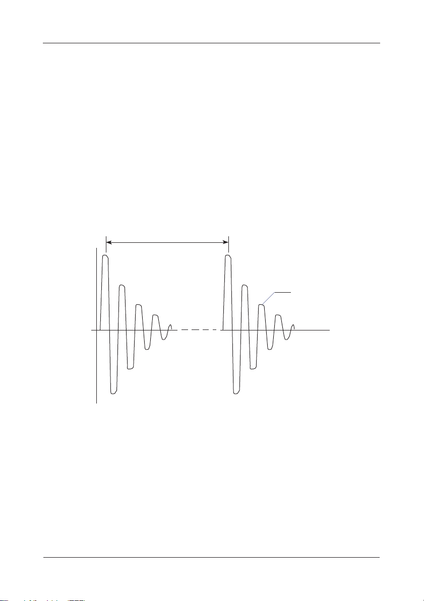
The PST-100 Spark Tester is intended to generate a high voltage
discharge, it is only to be used by responsible and authorised personnel
that have read and understood this manual.
The probe must NEVER be directed at the body.
There is a potential risk to those who might have an incipient heart
condition.
There is also a potential risk from the reflex action when receiving a high-
voltage shock. Injury could also occur if the spark were discharged to
sensitive parts of the body (e.g. eyes).
In a reasonably ventilated room of a volume greater than 40m3, the
exposure to ozone produced by the high voltage spark should not
present a risk to health. In a ‘confined space’ situation it is likely that
ozone levels will exceed the exposure limit and present some risk to
health. Under these conditions adequate ventilation must be provided.
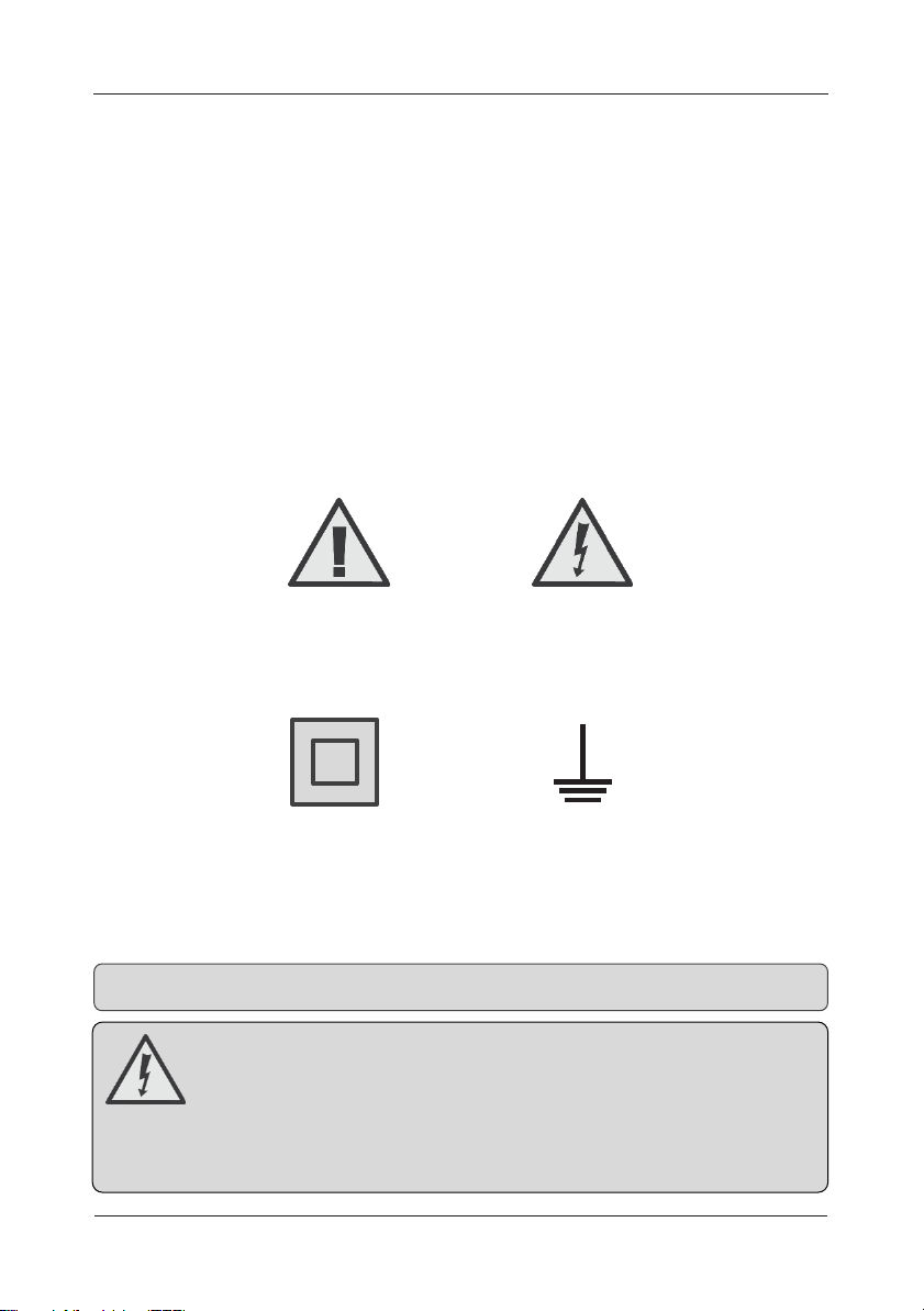
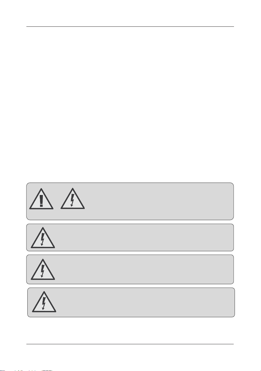
WARNING: This equipment must not be used in
any combustible atmosphere; the high voltage
discharge will cause a spark from which an
explosion could result.
WARNING: This equipment must not be exposed to damp or
wet conditions, or where the amount of conductive dust is
greater than would occur in a normal situation.
WARNING: Never connect or disconnect the electrode
with the PST-100 connected to the mains supply.
IMPORTANT: We strongly advise that individuals with
pacemakers do not use our high-voltage test equipment
under any circumstances.
Misuse or failure to comply with the guidelines outlined in this manual
may impair the safety provided by the equipment.