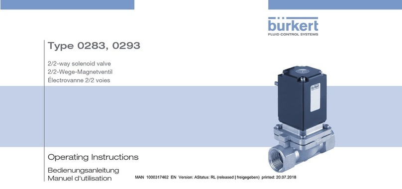
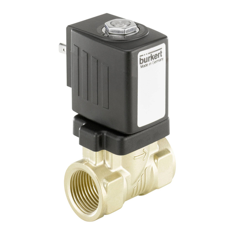
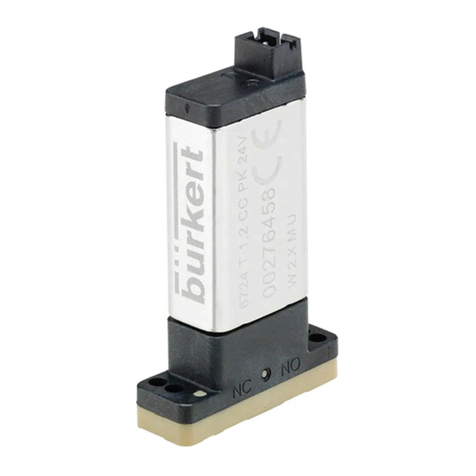
Burkert 2031 User manual
Other Burkert Control Unit manuals

Burkert
Burkert Robolux 2036 User manual

Burkert
Burkert 8697 User manual
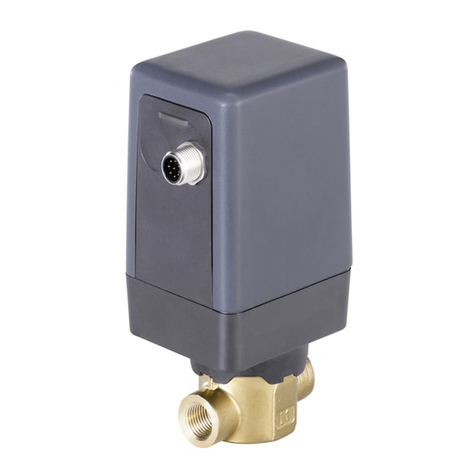
Burkert
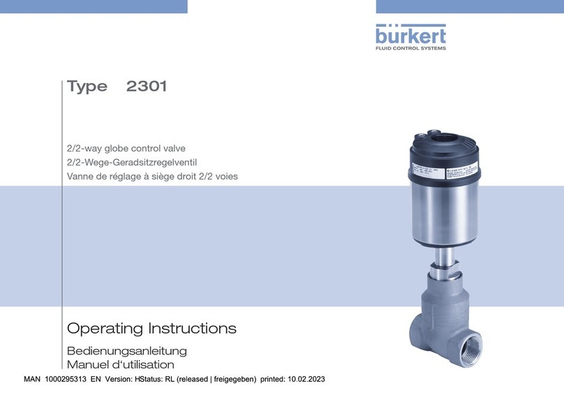
Burkert 3280 User manual
Burkert
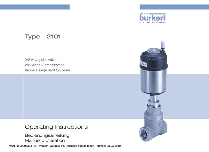
Burkert 219639 User manual
Burkert
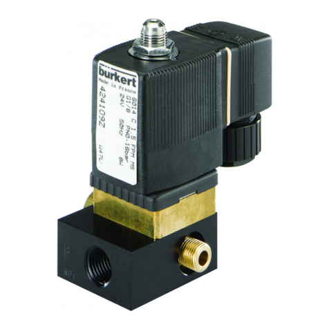
Burkert 2101 User manual
Burkert
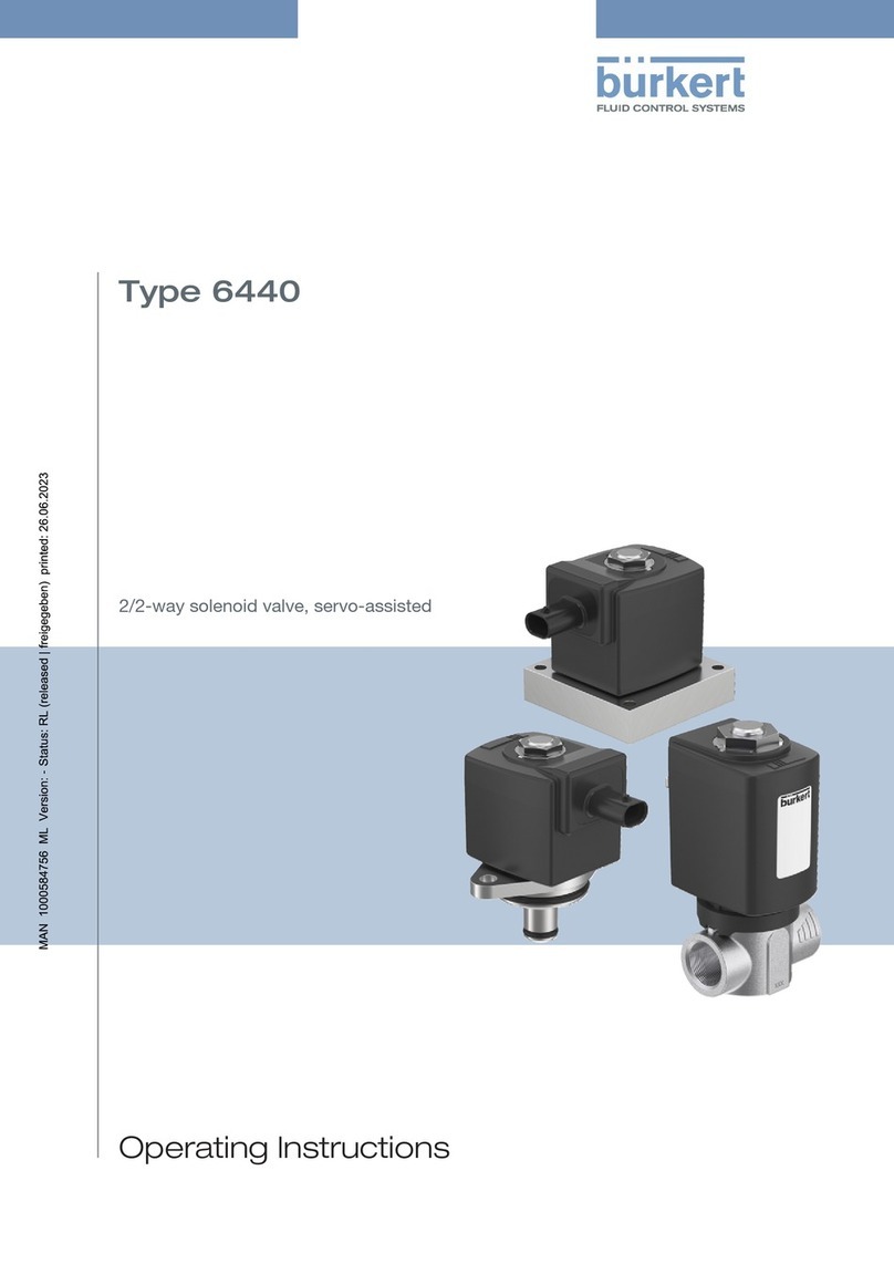
Burkert 6014 User manual
Burkert
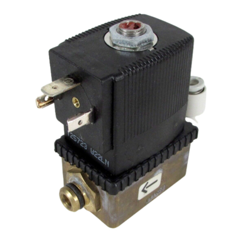
Burkert 6440 User manual
Burkert
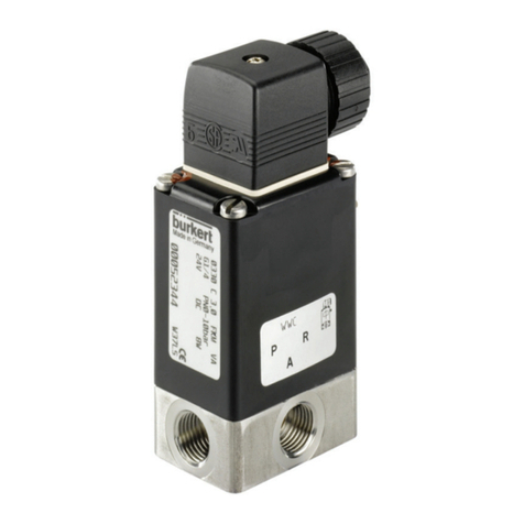
Burkert 6022 User manual
Burkert
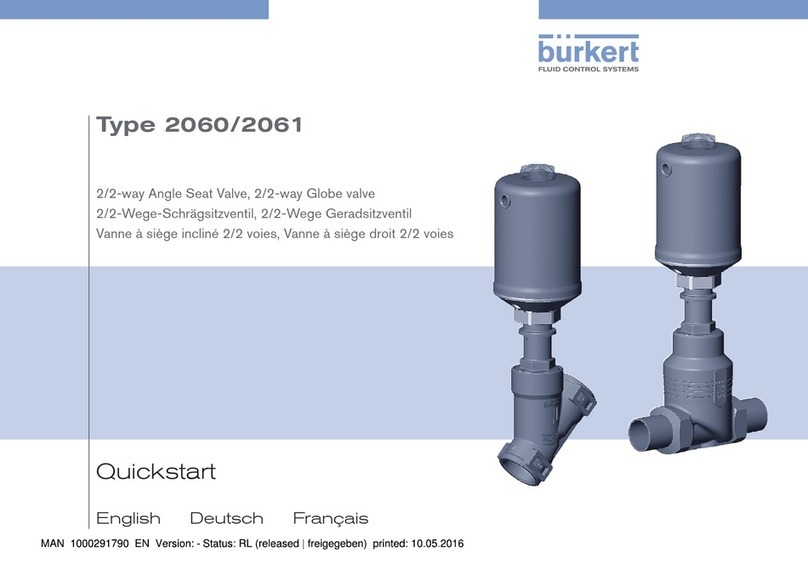
Burkert 0330 User manual
Burkert
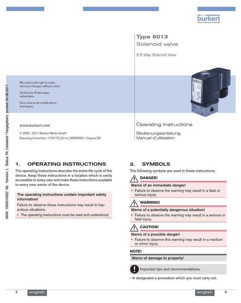
Burkert 2060 User manual
Burkert
Burkert Magnetventil 6013 User manual

Burkert
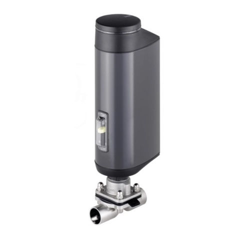
Burkert 3360 User manual
Burkert
Burkert 3323 User manual

Burkert
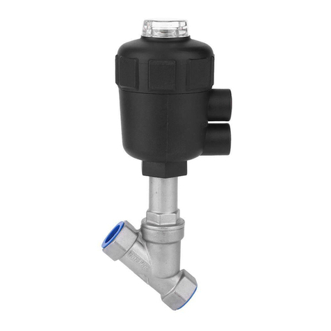
Burkert 2030 User manual
Burkert
Burkert 2702 User manual

Burkert
Burkert 2101 User manual

Burkert
Burkert 2000 INOX User manual

Burkert
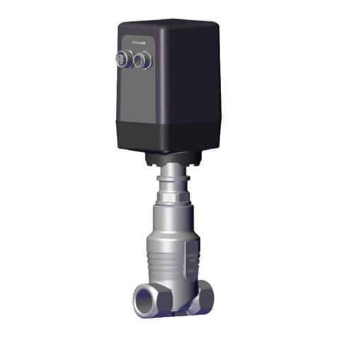
Burkert 2301 Series User manual
Burkert
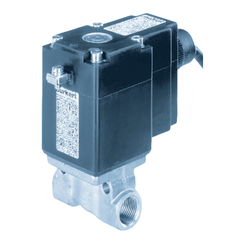
Burkert 3281 User manual
Burkert
Burkert PTB 00 ATEX 2202 X User manual
Popular Control Unit manuals by other brands

Festo
Festo Compact Performance CP-FB6-E Brief description

Elo TouchSystems
Elo TouchSystems DMS-SA19P-EXTME Quick installation guide

JS Automation
JS Automation MPC3034A user manual

JAUDT
JAUDT SW GII 6406 Series Translation of the original operating instructions

Spektrum
Spektrum Air Module System manual

BOC Edwards
BOC Edwards Q Series instruction manual

KHADAS
KHADAS BT Magic quick start

Etherma
Etherma eNEXHO-IL Assembly and operating instructions

PMFoundations
PMFoundations Attenuverter Assembly guide

GEA
GEA VARIVENT Operating instruction

Walther Systemtechnik
Walther Systemtechnik VMS-05 Assembly instructions

Altronix
Altronix LINQ8PD Installation and programming manual
