manuals.online logo
Brands
  1. Home
  2. •
  3. Brands
  4. •
  5. Burkert
  6. •
  7. Measuring Instrument
  8. •
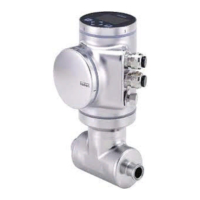
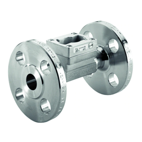
  9. Burkert FLOWave S 8098 User manual

Burkert FLOWave S 8098 User manual

Operating Instructions
Type 8098
FLOWave S
Flowmeter
We reserve the right to make technical changes without notice.
Technische Änderungen vorbehalten.
Sous réserve de modifications techniques.
© Bürkert Werke GmbH & Co. KG, 2019 - 2021
Operating Instructions 2101/02_EU-ML 00815332 / Original DE
3
Type 8098
1ABOUT THESE OPERATING INSTRUCTIONS ...................................................................................15
1.1 Symbols used ............................................................................................................................ 15
1.2 Denition ....................................................................................................................................15
2INTENDED USE ....................................................................................................................................16
2.1 DevicewithATEXapproval........................................................................................................16
3BASIC SAFETY INFORMATION ...........................................................................................................17
4GENERAL INFORMATION....................................................................................................................19
4.1 Manufacturer'saddressandinternationalcontacts ................................................................19
4.2 Warrantyconditions...................................................................................................................19
4.3 InformationontheInternet........................................................................................................19
5DESCRIPTION ......................................................................................................................................20
5.1 Structure.....................................................................................................................................20
5.1.1 Transmitter variants ....................................................................................................20
5.1.2 Unlocking magnetic key .............................................................................................20
5.2 Typelabel,adhesivelabel..........................................................................................................21
5.3 Typelabellasered ......................................................................................................................22
5.4 Certicationmarkings................................................................................................................23
5.5 MarkingoftheUniqueSerialNumber(USN) ............................................................................23
5.6 Descriptionofthestatusindicator...........................................................................................23
6TECHNICAL DATA ................................................................................................................................24
6.1 Operatingconditions .................................................................................................................24
6.2 Conformity..................................................................................................................................24
6.3 Standardsanddirectives...........................................................................................................24
6.3.1 Conformity to the Pressure Equipment Directive .......................................................25
6.3.2 ULcertication ...........................................................................................................25
6.3.3 EHEDGcertication....................................................................................................26
6.4 Fluiddata.................................................................................................................................... 27
6.5 Measurementdata .....................................................................................................................29
Type 8098 FLOWave S
English
4
Type 8098
6.6 Electricaldata ............................................................................................................................30
6.7 Mechanicaldata.........................................................................................................................31
7INSTALLATION IN THE PIPE ................................................................................................................32
7.1 Safetyinstructions .....................................................................................................................32
7.2 Preparingthedevicebeforeinstallationintothepipeline........................................................ 33
7.2.1 Changing the position of the transmitter on the sensor .............................................34
7.3 Recommendationsfortheinstallationintothepipeline ..........................................................35
7.4 Installingthedeviceintothepipe .............................................................................................37
7.4.1 Before installing the device into the pipe....................................................................37
7.4.2 Installing a device with clamp connections................................................................38
7.4.3 Installingadevicewithangeconnections ................................................................38
8ELECTRICAL INSTALLATION...............................................................................................................39
8.1 Safetyinstructions .....................................................................................................................39
8.2 Additionaldocumentation .........................................................................................................40
8.3 Connectingthedevicetoapowersupply ................................................................................41
8.4 ConnectingthedevicetoabüS/CANopennetworkwithoutoutputs ..................................42
8.5 ConnectingthedevicetoabüS/CANopennetworkwithoutputs........................................43
8.6 Connectingtheprotectiveearth................................................................................................44
9HOW TO DO THE SETTINGS ...............................................................................................................45
9.1 Safetyinstructions .....................................................................................................................45
9.2 PreparingtheBürkertCommunicatorsoftware........................................................................ 45
9.2.1 Connecting büS device with Bürkert Communicator .................................................45
9.3 Availableloginuserlevels .........................................................................................................46
9.4 Defaultsettings ..........................................................................................................................46
10 GENERAL SETTINGS - PARAMETER..................................................................................................47
10.1 Safetyinstructions .....................................................................................................................47
10.2 Userlevelsoftheeditablemenuitems.....................................................................................47
10.3 Defaultsettings ..........................................................................................................................47
10.4 Changingtheoperatingmodeofthestatusindicatororswitchingothestatusindicator..48
10.4.1 Changing the operating mode of the status indicator ................................................48
English
5
Type 8098
10.4.2 Switchingothestatusindicator ...............................................................................48
10.5 SettingthebasicparametersforidentifyingthedeviceonbüS..............................................49
10.5.1 Entering a name for the device...................................................................................49
10.5.2 Entering the location of the device .............................................................................49
10.5.3 Entering a description for the device..........................................................................50
10.6 SettingtheadvancedparametersforidentifyingthedeviceconnectedtobüSortoa
CANopeneldbus ......................................................................................................................50
10.6.1 Entering a unique name for the device.......................................................................50
10.6.2 Changing the transmission speed on the device .......................................................51
10.6.3 Activating the device internal termination resistor......................................................51
10.6.4 Deactivating the device internal termination resistor..................................................52
10.6.5 ChangingtheaddressofthedeviceconnectedtoaCANopeneldbus ...................52
10.6.6 SettingthedigitalcommunicationforbüSorforaCANopeneldbus ......................53
10.6.7 Stop sending the measured process data (PDOs) to büS or to the CANopen
eldbus .......................................................................................................................54
10.7 Monitoringthedevicesupplyvoltageorthedevicetemperature ...........................................54
10.7.1 Reading out the 2 error limit values............................................................................56
10.7.2 Changing the 2 warning limit values...........................................................................56
10.7.3 Reading out the hysteresis value................................................................................56
10.8 Readingoutthelowwarninglimitforthevoltageoftheinternalbattery ...............................57
10.9 Activatingthediagnosticsfunctions.........................................................................................57
10.10Disablingallthediagnostics ..................................................................................................... 58
11 GENERAL SETTINGS - DIAGNOSTICS ...............................................................................................59
11.1 Userlevelsofthemenuitems ...................................................................................................59
11.2 Readingoutdatarelatedtothedevice.....................................................................................59
11.2.1 Reading out the number of operating hours of the device.........................................59
11.2.2 Reading out the current value of the internal temperature of the device ...................59
11.2.3 Reading out the minimum or the maximum value of the internal temperature
of the device ...............................................................................................................60
11.2.4 Reading out the current value of the supply voltage..................................................60
11.2.5 Reading out the minimum or the maximum value of the supply voltage ...................60
11.2.6 Reading out the current value of the current consumption of the device ..................61
11.2.7 Reading out the minimum or the maximum value of the current consumpti-
on of the device ..........................................................................................................61
11.2.8 Reading out the number of device starts ...................................................................61
11.2.9 Checking whether the date and time are correct .......................................................62
English
6
Type 8098
11.2.10 Checking the voltage of the internal battery...............................................................62
11.3 ReadingoutdatarelatedtobüS ...............................................................................................63
11.3.1 Reading out the number of current receive errors......................................................63
11.3.2 Reading out the maximum number of receive errors since the last power-up
of the device ...............................................................................................................63
11.3.3 Reading out the number of current transmit errors ....................................................63
11.3.4 Reading out the maximum number of transmit errors since the last power-
up of the device..........................................................................................................64
11.3.5 Resetting the 2 maximum error counters ...................................................................64
11.3.6 Reading out whether the measured process data (PDO, process data ob-
ject)issentonbüSorontheCANopeneldbus .......................................................64
12 GENERAL SETTINGS - MAINTENANCE..............................................................................................65
12.1 Userlevelsofthemenuitems ...................................................................................................65
12.2 Readingoutsomedeviceinformation ......................................................................................65
12.2.1 Reading out the displayed name of the device ..........................................................65
12.2.2 Reading out the article number of the device ............................................................65
12.2.3 Reading out the serial number of the device..............................................................65
12.2.4 Reading out the article number of the device software..............................................66
12.2.5 Reading out the version number of the device software............................................66
12.2.6 Reading out the version number of the büS software................................................66
12.2.7 Reading out the version number of the device hardware...........................................66
12.2.8 Reading out the Type number of the device...............................................................67
12.2.9 Reading out the manufacturing date of the device ....................................................67
12.2.10 Readingouttheversionoftheembeddededsle.....................................................67
12.3 Restartingorresettingthedevice............................................................................................. 68
12.3.1 Restarting the device..................................................................................................68
12.3.2 Resetting the device to all its factory settings............................................................68
13 SAW SENSOR - PARAMETER .............................................................................................................69
13.1 Safetyinstructions .....................................................................................................................69
13.2 Userlevelsoftheeditablemenuitems.....................................................................................69
13.3 Defaultsettings ..........................................................................................................................69
13.4 Settingtheparametersofthevolumeowrate .......................................................................70
13.4.1 Givingauserdenednametothemeasuredvolumeowrate .................................70
13.4.2 Activatingthedampingofthevolumeowratevaluesandselectingapre-
deneddampinglevel ................................................................................................70
English
7
Type 8098
13.4.3 Activatingauser-deneddampingofthevolumeowratevalues............................72
13.4.4 Deactivatingthedampingofthevolumeowratevalues..........................................73
13.4.5 Activatingthemonitoringofthevolumeowrate ......................................................73
13.4.6 Deactivatingthemonitoringofthevolumeowrate ..................................................75
13.4.7 Changing the error limits, the warning limits and the hysteresis of the volu-
meowrate ................................................................................................................76
13.4.8 Resetting the default values of the error limits, the warning limits and the
hysteresisofthevolumeowrate ..............................................................................77
13.4.9 Enabling thecut-ofunction ......................................................................................78
13.4.10 Changing thecut-ovalueoftheowrate ................................................................79
13.4.11 Disabling thecut-ofunction .....................................................................................79
13.4.12 Resettingthedefaultvaluesofallthevolumeowrateparameters ..........................80
13.5 Settingtheparametersoftheliquidtemperature.....................................................................81
13.5.1 Givingauserdenednametothemeasuredliquidtemperature...............................81
13.5.2 Activating the damping of the liquid temperature values and selecting a
predeneddampinglevel ...........................................................................................81
13.5.3 Activatingauser-deneddampingoftheliquidtemperaturevalues .........................83
13.5.4 Deactivating the damping of the liquid temperature values .......................................84
13.5.5 Activating the monitoring of the liquid temperature ...................................................85
13.5.6 Deactivating the monitoring of the liquid temperature ...............................................86
13.5.7 Changing the error limits, the warning limits and the hysteresis of the liquid
temperature ................................................................................................................86
13.5.8 Resetting the default values of the error limits, the warning limits and the hyste-
resis of the liquid temperature................................................................................................87
13.5.9 Resetting the default values of all the liquid temperature parameters .......................87
13.6 Settingtheparametersoftheliquidvelocity............................................................................88
13.6.1 Givingauserdenednametothemeasuredliquidvelocity......................................88
13.6.2 Activatingthedampingoftheliquidvelocityvaluesandselectingaprede-
ned damping level ......................................................................................................88
13.6.3 Activatingauser-deneddampingoftheliquidvelocityvalues ................................90
13.6.4 Deactivating the damping of the liquid velocity values ..............................................91
13.6.5 Activating the monitoring of the liquid velocity...........................................................91
13.6.6 Deactivating the monitoring of the liquid velocity.......................................................92
13.6.7 Changing the error limits, the warning limits and the hysteresis of the liquid
velocity........................................................................................................................93
13.6.8 Resetting the default values of the error limits, the warning limits and the
hysteresis of the liquid velocity...................................................................................93
English
8
Type 8098
13.6.9 Resetting the default values of all the liquid velocity parameters ..............................94
13.7 Settingtheparametersofthetotalizers....................................................................................95
13.7.1 Givingauserdenednametoeachtotalizer .............................................................95
13.7.2 Selectingthecountingdirectionofeachtotalizer ......................................................95
13.7.3 Activatingthemonitoringofeachtotalizervalue........................................................96
13.7.4 Deactivatingthemonitoringofeachtotalizer .............................................................97
13.7.5 Changingtheerrorlimits,thewarninglimitsandthehysteresisofeachtotalizer .....97
13.7.6 Resetting the default values of the error limits, the warning limits and the
hysteresisofeachtotalizer .........................................................................................98
13.7.7 Enablingtheusertostart,stoporreseteachtotalizer...............................................98
13.7.8 Disablingtheusertostart,stoporreseteachtotalizer..............................................99
13.7.9 Startingatotalizer.......................................................................................................99
13.7.10 Stoppingatotalizer.....................................................................................................99
13.7.11 ResettingeachtotalizertoaPresetvalue ..............................................................100
13.7.12 Changing the Presetvalueforatotalizerreset .......................................................100
13.7.13 Resettingtheoverowcounterofatotalizer ............................................................101
13.7.14 Resettingalltheparametersofatotalizertothedefaultvalues...............................101
13.8 Settingtheparametersofthedensityfactor(optionalfeature).............................................102
13.8.1 What is the density factor?.......................................................................................102
13.8.2 Givingauserdenednametothemeasureddensityfactor....................................102
13.8.3 Activating the monitoring of the density factor.........................................................103
13.8.4 Deactivating the monitoring of the density factor.....................................................103
13.8.5 Changing the error limits, the warning limits and the hysteresis of the densi-
ty factor.....................................................................................................................104
13.8.6 Resetting the default values of the error limits, the warning limits and the
hysteresis of the density factor.................................................................................105
13.8.7 Setting the temperature compensation to measure the density factor ....................105
13.8.8 Setting the temperature compensation for a liquid other than water.......................106
13.8.9 Activating the temperature compensation for water ................................................107
13.8.10 Resetting the default values of all the density factor parameters.............................107
13.8.11 Use case example of the density factor ...................................................................108
13.9 Settingtheparametersoftheacoustictransmissionfactor(optionalfeature).....................109
13.9.1 What is the acoustic transmission factor?................................................................109
13.9.2 Givingauserdenednametothemeasuredacoustictransmissionfactor.............110
13.9.3 Changing the error limits, the warning limits and the hysteresis of the acou-
stic transmission factor.............................................................................................111
13.9.4 Activating the monitoring of the acoustic transmission factor .................................112
English
9
Type 8098
13.9.5 Deactivating the monitoring of the acoustic transmission factor .............................113
13.9.6 Resetting the default values of the error limits, the warning limits and the hystere-
sis of the acoustic transmission factor .................................................................................. 113
13.9.7 Resetting the default values of all the acoustic transmission factor parameters .....114
13.10Diagnostics:monitoringspecialeventsintheprocess,onthesensororontheelectronics....
114
13.10.1 Enabling the diagnostics for special events in the process .....................................118
13.10.2 Disabling the diagnostics for special events in the process.....................................119
13.10.3 Enabling the diagnostics for special events on the electronics................................119
13.10.4 Disabling the diagnostics for special events on the electronics...............................120
13.10.5 Enabling the diagnostics for special events on the sensor ......................................120
13.10.6 Disabling the diagnostics for special events on the sensor .....................................121
13.11Gettingasaccuratemeasurementsofthevolumeowrateortheliquidvelocityaspossible.
122
13.11.1 Activating the viscosity compensation for water like liquids....................................123
13.11.2 Activating the compensation for a liquid with a constant viscosity..........................123
13.11.3 Activating the compensation for a liquid with a linear viscosity compensati-
on curve....................................................................................................................124
13.11.4 Activating the compensation for a liquid with a quadratic viscosity compen-
sation curve ..............................................................................................................125
13.11.5 Activating the compensation for a liquid with an inverse quadratic viscosity
compensation curve .................................................................................................126
13.11.6 Resetting the default values of the viscosity compensation parameters .................126
13.12Settingtherefreshtime ...........................................................................................................127
13.12.1 Use case of the refresh time.....................................................................................127
13.12.2 Changing the refresh time ........................................................................................127
14 SAW SENSOR - DIAGNOSTICS.........................................................................................................128
14.1 Readingoutthegeneratedeventsrelatedtothedevice .......................................................128
14.2 Readingouttheowdirectionthathasbeenset ..................................................................128
14.3 Readingoutthetemperaturesoftheelectronicboardsandoftheliquid ............................128
14.4 Readingouttherefreshtimethathasbeenset .....................................................................129
14.5 Readingouttheoperatinghoursofthedevice ......................................................................129
14.6 Readingouttheoperatinghoursofthemeasurementboard................................................129
14.7 Readingoutthediagnosticsrelatedtotheoutputvalues .....................................................130
14.8 Readingoutthediagnosticseventsthatoccurredintheprocess........................................130
14.9 Readingoutthediagnosticseventsthatoccurredontheelectronics .................................130
English
10
Type 8098
14.10Readingoutthediagnosticseventsthatoccurredonthesensor ........................................131
14.11Readingoutthediagnosticsrelatedtothemonitoredlimits.................................................131
14.12Readingoutifaprocessvalueisinthemonitoredrange......................................................132
15 SAW SENSOR - MAINTENANCE .......................................................................................................133
15.1 Userlevelsoftheeditablemenuitems...................................................................................133
15.2 Defaultsettings ........................................................................................................................133
15.3 Readingoutdeviceinformation ..............................................................................................133
15.3.1 Reading out the order numbers of the device, the transmitter board and the
measurement board..................................................................................................133
15.3.2 Reading out the serial numbers of the device, the transmitter board and the
measurement board..................................................................................................134
15.3.3 Reading out the hardware and software versions of the transmitter board
and of the measurement board ................................................................................134
15.3.4 Reading out the characteristics of the measurement tube.......................................134
15.4 Settingthedirectionoftheow ..............................................................................................135
15.5 Calibratingtheosetvalueoftheowzeropoint..................................................................136
15.6 Settingtheosetvalueoftheowzeropoint ........................................................................137
15.7 SettingtheKfactor..................................................................................................................137
15.8 CalibratingtheKfactorbyusingateach-inprocedure ......................................................... 138
15.8.1 CalibratingtheKfactorbyusingateach-inproceduredependingontheowrate 138
15.8.2 Calibrating the K factor by using a teach-in procedure depending on a
known volume...........................................................................................................139
15.9 Resettingtheowratecalibrationdatatoitsdefaultvalues.................................................141
15.10Settingtheosetvalueoftheliquidtemperature ..................................................................141
15.11Calibratingtheosetvalueoftheliquidtemperature ............................................................142
15.12Resettingtheosetoftheliquidtemperaturetothedefaultvalue .......................................143
15.13Resettingallthecalibrationdatatoitsdefaultvalues(standardmeasurementvalues) ......143
15.14Settingtheosetvalueofthedensityfactor..........................................................................144
15.15Calibratingtheosetvalueofthedensityfactor ...................................................................145
15.16Settingthelinearityvalueofthedensityfactor ......................................................................146
15.17Settingtheosetvalueoftheacoustictransmissionfactor .................................................146
15.18Calibratingtheosetvalueoftheacoustictransmissionfactor ...........................................147
15.19Settingthelinearityvalueoftheacoustictransmissionfactor..............................................148
15.20Resettingallthecalibrationdatatothedefaultvalues(additionalmeasurementvalues) ...148
English
11
Type 8098
15.21Checkingthecorrectbehaviourofthedevice .......................................................................149
15.21.1 Selecting the process values to be simulated ..........................................................149
15.21.2 Checking the behaviour of the device by simulating an event.................................150
15.21.3 Stopping the simulation of process values and events ............................................150
16 OUTPUTS - PARAMETER ..................................................................................................................151
16.1 Defaultsettings ........................................................................................................................151
16.2 Changingthetypeofanoutput...............................................................................................151
16.3 Settingtheparametersofananalogueoutput.......................................................................152
16.3.1 Changing the process value and the process value range associated to an
analogue output........................................................................................................152
16.3.2 Selecting the damping level of the values transmitted on an analogue output........153
16.3.3 Conguringthebehaviourofananalogueoutputdependingonthestatus
of the device .............................................................................................................154
16.4 Disablingananalogueoutput .................................................................................................155
16.5 Settingtheparametersofadigitaloutput ..............................................................................156
16.5.1 Conguringadigitaloutputasanon/ooutput.......................................................157
16.5.2 Conguringadigitaloutputasanoutputwithswitchingthresholds .......................158
16.5.3 Conguringadigitaloutputasafrequencyoutput ..................................................159
16.5.4 Conguringadigitaloutputasapulseoutput .........................................................160
16.6 Resettingalltheparametersofanoutputtodefaultvalues..................................................161
16.7 Resettingalltheparametersofalltheoutputstothedefaultvalues.................................... 161
17 OUTPUTS - DIAGNOSTICS................................................................................................................ 162
17.1 Analogueoutput:readingoutthecurrentstatusandthevaluesofthecurrent ...................162
17.2 Digitaloutput:readingoutthemode,thecurrentstatusandthecurrentvalue...................162
18 OUTPUTS - MAINTENANCE .............................................................................................................. 163
18.1 Calibratingananalogueoutput ...............................................................................................163
18.2 Checkingthecorrectoperationofananalogueoutput .........................................................164
18.3 Resettingthecalibrationdataofananalogueoutputtothedefaultvalues .........................164
18.4 Resettingthecalibrationdataofalltheanalogueoutputstothedefaultvalues .................165
18.5 Checkingthecorrectoperationofanon/ooutputorathresholdoutput...........................165
18.6 Checkingthecorrectoperationofafrequencyoutput..........................................................166
18.7 Checkingthecorrectoperationofapulseoutput .................................................................166
English
12
Type 8098
19 MAINTENANCE AND TROUBLESHOOTING .....................................................................................167
19.1 Safetyinstructions ...................................................................................................................167
19.2 Informationonreturningthedevicetothemanufacturerortothereseller ..........................168
19.3 Cleaningtheoutersurfaceofthedevice................................................................................ 168
19.4 CleaningInPlace(CIP)ofthedevice......................................................................................168
19.5 SterilisationInPlace(SIP)ofthedevice .................................................................................169
19.6 Troubleshootingwhenamessageisdisplayed......................................................................170
19.7 Messageswhensettingwrongparameters............................................................................171
19.7.1 Kinematic viscosity ≤0.Checktheowviscositycompensation'sparameters ......171
19.8 Messagesduetodeviceinternaldiagnostics ........................................................................171
19.8.1 Message "Overvoltage detected".............................................................................171
19.8.2 Message "Undervoltage detected" ..........................................................................172
19.8.3 Message "Voltage is above the warning limit" .........................................................172
19.8.4 Message "Voltage is below the warning limit"..........................................................172
19.8.5 Message "Battery voltage is below the warning limit" .............................................173
19.8.6 Message"büSevent:busconnectionlost/notavailable"......................................173
19.8.7 Message "Overtemperature detected".....................................................................173
19.8.8 Message "Undertemperature detected"...................................................................174
19.8.9 Message "Temperature is above the warning limit" .................................................174
19.8.10 Message "Temperature is below the warning limit"..................................................174
19.8.11 Message"Internalmessagestoreoverow" ............................................................175
19.8.12 Message "No signals from interdigital transducer" ..................................................175
19.8.13 Message "No temperature sensor detected" ...........................................................175
19.8.14 Message "Pipe characteristics have changed: check limits values"........................175
19.8.15 Message"Measureboardisinbootstartermode,normwarefoundn°1" ............176
19.8.16 Message"DatareturnedbythemeasurementPCBisinvalidn°1"..........................176
19.8.17 Message "Communication between transmitter PCB and measurement
PCBhasbeeninterruptedn°x" ................................................................................176
19.8.18 Message"Themeasurementboardbootloaderoperationfailedn°1" ....................176
19.8.19 Message "An error occurred during communication" ..............................................177
19.8.20 Message"Max.owrate".........................................................................................177
19.8.21 Message "Max temperature"....................................................................................177
19.8.22 Message"Totalizer1stopped"or"Totalizer2stopped"..........................................177
19.8.23 Message"Totalizer1started"or"Totalizer2started"..............................................178
19.9 Messagesduetocalibrationorsimulation.............................................................................178
English
13
Type 8098
19.9.1 Message "Calibration result out of range"................................................................178
19.9.2 Message"Zerocalibrationcancelled,theowrateishigherthan5%offull
scale" .......................................................................................................................178
19.9.3 Message "Calibration cancelled" .............................................................................179
19.9.4 Message"Calibrationcancelled,theowrateislessthan5%ofthefullscale"....179
19.9.5 Message "Resulting K factor is less than 0.8 or higher than 1.2" ...........................179
19.9.6 Message"Resultingosetishigherthan10°C,18°F" ..........................................179
19.9.7 Message "Test mode activated"...............................................................................180
19.9.8 Message "Simulation mode active"..........................................................................180
19.10Messagesduetothemonitoringofprocessvalues ..............................................................180
19.10.1 Message"Flowratetoohigh" ..................................................................................180
19.10.2 Message"Flowratetoolow"....................................................................................181
19.10.3 Message "Temperature too high" .............................................................................181
19.10.4 Message "Temperature too low" ..............................................................................182
19.10.5 Message"Valuetotalizer1toohigh"or"Valuetotalizer2toohigh" ........................182
19.10.6 Message"Valuetotalizer1toolow"or"Valuetotalizer2toolow"...........................183
19.10.7 Message"Fluidvelocitytoohigh" ............................................................................183
19.10.8 Message"Fluidvelocitytoolow" .............................................................................184
19.10.9 Message "Density factor too high"...........................................................................184
19.10.10 Message "Density factor too low" ............................................................................185
19.10.11 Message "Acoustic transmission factor too high"....................................................185
19.10.12 Message "Acoustic transmission factor too low".....................................................186
19.11Messagesduetodiagnosticsevents .....................................................................................186
19.11.1 Message "Diagnostic is active" ................................................................................186
19.11.2 Message "Diagnostic is inactive" .............................................................................186
19.11.3 Message"Nottotallylled" ......................................................................................187
19.11.4 Message "Liquid out of range".................................................................................187
19.11.5 Message"Unstableowrate" ..................................................................................187
19.11.6 Message"Lowowcuto"......................................................................................188
19.11.7 Message "Change of liquid".....................................................................................188
19.11.8 Message"Backwardow" .......................................................................................188
19.11.9 Message "Sound conductivity out of range"............................................................189
19.11.10 Message "AO1 open loop" or "AO3 open loop" ......................................................189
19.11.11 Message "AO1 Diag error" or "AO3 Diag error" .......................................................189
19.11.12 Message "DO2 overload" or "DO3 overload" ..........................................................190
English
14
Type 8098
20 SPARE PARTS AND ACCESSORIES .................................................................................................191
21 PACKAGING,TRANSPORT................................................................................................................192
22 STORAGE ...........................................................................................................................................192
23 DISPOSAL OF THE DEVICE...............................................................................................................192
English
15
About these operating instructions
Type 8098
1 ABOUT THESE OPERATING INSTRUCTIONS
The operating instructions describe the entire life cycle of the device. Please keep the operating instructions
in a safe place, accessible to all users and any new owners.
Theoperatinginstructionscontainimportantsafetyinformation.
Failuretocomplywiththeseinstructionscanleadtohazardoussituations.Payattentioninparticularto
the chapters 3 Basic safety information and 2 Intended use.
▶Irrespective of the device version, the operating instructions must be read and understood.
1.1 Symbols used
DANGER
Warnsagainstanimminentdanger.
▶Failuretoobservethiswarningresultsindeathorinseriousinjury.
WARNING
Warnsagainstapotentiallydangeroussituation.
▶Failuretoobservethiswarningcanresultinseriousinjuryorevendeath.
CAUTION
Warnsagainstapossiblerisk.
▶Failuretoobservethiswarningcanresultinsubstantialorminorinjuries.
NOTICE
Warnsagainstmaterialdamage.
Indicates additional information, advice or important recommendations.
Refers to information contained in these Operating Instructions or in other documents.
▶Indicates an instruction to be carried out to avoid a danger, a warning or a possible risk.
→Indicates a procedure to be carried out.
A highlightedterm is related to a menu or a menu item.
Indicatestheresultofaspecicinstruction.
1.2 Denition
Theterm"device"usedintheseoperatinginstructionsalwaysreferstotheowmeterType8098FLOWaveS.
The term “büS” (Bürkert system bus) used in this instruction stands for the communication bus developed
by Bürkert and based on the CANopen protocol.
English
16
About these operating instructions
Type 8098
→FormoreinformationonthedeviceviabüS,seetheEnglish"CablingguideforbüS/EDIP"atwww.
burkert.com.
→FormoreinformationonCANopenwhichisrelatedtothedevice,refertotheoperatinginstructions
"CANopenNetworkconguration"atwww.burkert.com.
2 INTENDED USE
TheowmeterType8098FLOWaveSusestheSurfaceAcousticWave(SAW)measurementprinciple
andisintendedtomeasuretheowrateofliquidsthathaveallthefollowingcharacteristics:
- clean liquids
- nonemulsiedliquids(homogeneousliquids)
- liquids that are free of air bubbles
- liquids that are free of gas bubbles
- liquids that are free of solids.
▶Thedeviceisnotintendedtomeasuretheowrateofliquidsifgasbubblesarepresent,whateverthe
origin of the bubbles (air intake, cavitation, degassing…).
▶Use the device only as intended. Use of the device that does not comply with the instructions could
present risks to people, nearby installations and the environment.
▶Properly transport, store, install and operate the device.
▶Use the device in compliance with the characteristics and the conditions of commissioning and use
speciedinthecontractualdocumentsandintheoperatinginstructions.
▶Protect the device against electromagnetic interference, ultraviolet rays and, when installed outdoors,
againsttheeectsofclimaticconditions.
▶Do not use the device without ATEX approval in a potentially explosive atmosphere.
▶Only operate a device in perfect working order.
2.1 Device with ATEX approval
DANGER!
Riskofexplosionintheeventofimproperuseofthedeviceinpotentiallyexplosiveareas.
▶ObservethespecicationsoftheATEX-conformitycerticate.
▶ObservethespecicationsgivenintheATEXsupplementforType8098FLOWaveS.Thesupplementis
available at www.burkert.com
The ATEX approval is only valid if the device is used as described in the ATEX supplement.
Ifunauthorizedchangesaremadetothedevice,thentheATEXapprovalbecomesinvalid.
English
17
Basic safety information
Type 8098
3 BASIC SAFETY INFORMATION
This safety information does not take into account any contingencies or occurrences that may arise during
installation, use and maintenance of the product.
Theoperatingcompanyisresponsiblefortherespectofthelocalsafetyregulations,includingstasafety.
Riskofinjuryduetoelectricalvoltage.
▶Before carrying out work on the system, disconnect the electrical power for all the conductors and isolate it.
▶AccordingtoUL/EN6101010-1:
DoubleisolatealldevicesconnectedtotheowmeterType8098fromthemainsandnotethatthese
arelimitedenergycircuitsforallcircuitsconnectedtotheowmeterType8098.
▶Observe all applicable accident protection and safety regulations for electrical equipment.
Riskofinjuryduetohighpressureintheinstallation.
▶Beforeanyinterventionintheinstallation,stopthecirculationofuid,cutothepressureanddrainthe
pipe.
▶Before any intervention in the installation, make sure there is no pressure in the pipe.
▶Observethedependencybetweentheuidtemperatureandtheuidpressureforthettingused.
Ifswitchedonforaprolongedtime,riskofburnsorreduetohotdevicesurfaces
▶Do not touch with bare hands.
▶Keepthedeviceawayfromhighlyammablesubstancesanduids.
Riskofburnsduetohighuidtemperatures.
▶Donottouchwithbarehandsthepartsofthedevicethatareincontactwiththeuid.
▶Use safety gloves to handle the device.
▶Beforeopeningthepipe,stopthecirculationofuidanddrainthepipe.
▶Before opening the pipe, make sure the pipe is completely empty.
Riskofinjuryduetothenatureoftheuid.
▶Respect the prevailing regulations on accident prevention and safety relating to the use of dangerous
uids.
English
18
Basic safety information
Type 8098
Generaldangeroussituations
To avoid injury, observe the following instructions:
▶Do not use the device in explosive atmospheres.
▶Do not use the device in an environment incompatible with the device materials.
▶Onlyuseuidscompatiblewiththedevicematerials.Findthechemicalresistancechartunderwww.
burkert.com
▶Do not subject the device to mechanical loads.
▶Donotmakeanymodicationstothedevice.
▶Prevent any unintentional power supply switch-on.
▶Onlyqualiedandskilledstamaycarryoutinstallationandmaintenancework.
▶Ensureadenedorcontrolledrestartingoftheprocessafterapowersupplyinterruption.
▶Observe the general technical rules.
CAUTION
Riskofinjuryduetoaheavydevice.
A heavy device can fall down during transport or during installation and cause injuries.
▶Transport, install and dismantle a heavy device with the help of another person.
▶Use appropriate tools.
NOTICE
Elements or components sensitive to electrostatic discharges.
This device contains electronic components that are sensitive to electrostatic discharges. They may be
damaged if they are touched by an electrostatically charged person or object. In the worst case scenario,
these components are instantly destroyed or disabled as soon as they are activated.
▶To minimise or even avoid any damage caused by an electrostatic discharge, take all the precautions
described in standard EN 61340-5-1.
▶Also make sure that you do not touch any of the live electrical components.
English
19
General information
Type 8098
4 GENERAL INFORMATION
4.1 Manufacturer's address and international contacts
To contact the manufacturer of the device, use the following address:
Bürkert SAS
Rue du Giessen
BP 21
F-67220TRIEMBACH-AU-VAL
YoumayalsocontactyourlocalBürkertsalesoce.
Theaddressesofourinternationalsalesocesareavailableontheinternetat:
www.burkert.com
4.2 Warranty conditions
The condition governing the legal warranty is the conforming use of the device in observance of the oper-
atingconditionsspeciedintheOperatingInstructions.
4.3 Information on the Internet
YoucanndtheoperatinginstructionsandthetechnicaldatasheetsforType8098at:
www.burkert.com
English
20
Description
Type 8098
5 DESCRIPTION
5.1 Structure
TheType8098owmeterismadeupofaTypeSE91transmitterandaTypeS097owsensor.
Process connection
Sensor housing
Status indicator and seal
Grounding connection (protective earth)
Transmitter
Electrical connection
Seal
Figure 1: Description
5.1.1 Transmitter variants
Variants:
•Without outputs
•With2outputsthatcanbeconguredasanalogueordigitaloutputs
5.1.2 Unlocking magnetic key
The device is delivered with a magnetic key to unlock the transmitter.
Figure 2: Unlocking magnetic key
English

Other manuals for FLOWave S 8098

1

Other Burkert Measuring Instrument manuals

Burkert FLOWave S 8098 User manual

Burkert

Burkert FLOWave S 8098 User manual

Burkert Flowave 8098 User manual

Burkert

Burkert Flowave 8098 User manual

Burkert Flowave 8098 User manual

Burkert

Burkert Flowave 8098 User manual

Burkert 8026 User manual

Burkert

Burkert 8026 User manual

Burkert 8202 ELEMENT User manual

Burkert

Burkert 8202 ELEMENT User manual

Burkert 8202 ELEMENT User manual

Burkert

Burkert 8202 ELEMENT User manual

Burkert 8743 User manual

Burkert

Burkert 8743 User manual

Burkert 8071 User manual

Burkert

Burkert 8071 User manual

Burkert 8202 ELEMENT User manual

Burkert

Burkert 8202 ELEMENT User manual

Burkert 8020 User manual

Burkert

Burkert 8020 User manual

Burkert 8026 User manual

Burkert

Burkert 8026 User manual

Burkert 8012 Series User manual

Burkert

Burkert 8012 Series User manual

Burkert 8041 User manual

Burkert

Burkert 8041 User manual

Burkert 8285 User manual

Burkert

Burkert 8285 User manual

Burkert FLOWave L User manual

Burkert

Burkert FLOWave L User manual

Burkert 8035 User manual

Burkert

Burkert 8035 User manual

Burkert 8644 AirLINE User manual

Burkert

Burkert 8644 AirLINE User manual

Burkert 8025 UNIVERSAL User manual

Burkert

Burkert 8025 UNIVERSAL User manual

Burkert 8228 ELEMENT User manual

Burkert

Burkert 8228 ELEMENT User manual

Burkert AC10 User manual

Burkert

Burkert AC10 User manual

Burkert MassFlowMeter 8700 User manual

Burkert

Burkert MassFlowMeter 8700 User manual

Burkert 8746 User manual

Burkert

Burkert 8746 User manual

Burkert 8203 User manual

Burkert

Burkert 8203 User manual

Burkert 8285 El. COND User manual

Burkert

Burkert 8285 El. COND User manual

Popular Measuring Instrument manuals by other brands

Konica Minolta AeroDR System Operation manual

Konica Minolta

Konica Minolta AeroDR System Operation manual

Akai GX-280 Operator's manual

Akai

Akai GX-280 Operator's manual

Tintometer Lovibond MD100 instruction manual

Tintometer

Tintometer Lovibond MD100 instruction manual

RadComm RC2PLUS user manual

RadComm

RadComm RC2PLUS user manual

OHAUS AB23PH instruction manual

OHAUS

OHAUS AB23PH instruction manual

KERN Optics ORA 80 BE operating manual

KERN Optics

KERN Optics ORA 80 BE operating manual

Fungilab Visco Ball V9000 Operation manual

Fungilab

Fungilab Visco Ball V9000 Operation manual

hager EC377M User instructions

hager

hager EC377M User instructions

Bacharach PCA 400 user manual

Bacharach

Bacharach PCA 400 user manual

GEORGE FISCHER +GF+ SIGNET 9020 Intelek-Pro instruction manual

GEORGE FISCHER

GEORGE FISCHER +GF+ SIGNET 9020 Intelek-Pro instruction manual

FLIR EXTECH HDV-TX1 Product sheet

FLIR

FLIR EXTECH HDV-TX1 Product sheet

Berthold MicroPolar LB 566 user guide

Berthold

Berthold MicroPolar LB 566 user guide

ACIN Betz 2500/250 manual

ACIN

ACIN Betz 2500/250 manual

Lascar DPM 160 Application notes

Lascar

Lascar DPM 160 Application notes

Doza DROZD user manual

Doza

Doza DROZD user manual

IDEAL 61-702 manual

IDEAL

IDEAL 61-702 manual

RS PRO RS-136 instruction manual

RS PRO

RS PRO RS-136 instruction manual

THORLABS PM100A quick reference

THORLABS

THORLABS PM100A quick reference

manuals.online logo
manuals.online logoBrands
  • About & Mission
  • Contact us
  • Privacy Policy
  • Terms and Conditions

Copyright 2025 Manuals.Online. All Rights Reserved.