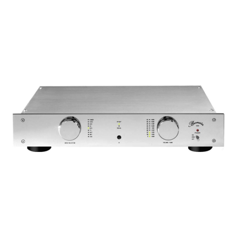
Burmester Classic 101 User manual

Classic Line
101 Integrated Amplifier
Owner‘s Manual


101 Integrated Amplifier 3
T C
A T D ....................................................
A T O I ...................................
Used symbols and characters ........................................................6
Meaning of warning symbols and words ..............................................6
I S I .........................................
Unpacking ........................................................................7
Set-up ............................................................................7
Connecting........................................................................7
Power on..........................................................................8
Operation .........................................................................8
Maintenance and care ..............................................................8
U S U D...................................
Unpacking ........................................................................9
Supplied items ..........................................................................9
Packaging ..............................................................................9
Set-up ............................................................................9
T D G...............................................
Front side ........................................................................10
Back side.........................................................................11
The remote control ................................................................12
C D...............................................
Connecting the inputs .............................................................13
Connecting the outputs ............................................................14
Important information regarding connection ...............................................14
Connecting the speaker outputs ..........................................................15
Connecting the preamplifier output .......................................................16
Connecting headphones ................................................................16
BURLINK interface.................................................................16
Connecting the remote output ......................................................17
Connecting the power cord ........................................................17
O D ................................................
Power on/off......................................................................18
Selecting a signal source ...........................................................19
Adjusting the volume ..............................................................19
Smooth function ..................................................................20
Subsonic filter (optional) ...........................................................20
Pre-out only mode.................................................................21
4
Surround Thruput function .........................................................21
Remote output....................................................................22
Protective functions................................................................22
BURLINK (BUR LINK C) ...............................
Connectors.......................................................................23
Commands.......................................................................23
M, R, C .......................................
Replacing defective fuses ..........................................................24
Cleaning the device ...............................................................24
D............................................................
W...........................................................
T D ......................................................

ABOUT THIS DEVICE
101 Integrated Amplifier 5
A T D
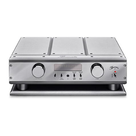
The 101 integrated amplifier is the latest integrated amplifier in the Burmester product
range and serves as a prime example of the perfect combination of efficient class-D
power amps with an analog power supply. With the power reserves it provides, the 101
effortlessly achieves the warm and well-balanced sound so characteristic of Burmester
products, all in a compact design. The switchable “Smooth” function also ensures a
rounded, detailed sound, even at low volumes.
Within the Burmester soundscape, the 101 integrated amplifier is the ideal partner for
the 102 CD player, especially when combined with speakers from the Burmester
portfolio.
Preamp function: the additional balanced outputs also enable the use as a pure
preamp in top-notch high-end quality or a later upgrading with external power
amplifiers.
As expected from Burmester, the 101 also features a fully balanced circuit layout. Its
pre-out and headphone amplifiers are DC-coupled, meaning they dispense entirely
with distorting coupling capacitors in the signal path.
Surround Thruput function: With the Thruput the 101 can easily integrate surround
components into a stereo system. To this end the XLR input AUX 2 (21) may be used to
connect the two front channels of a surround decoder / processor. After turning on the
Surround Thruput the signals are now independently slaved through directly to the
outputs.
Highlights:
• Pre-out in absolute high-end quality
• Headphone output on the front
• Efficient class-D power amps
• Analog power supply
• Switchable “Smooth” function
• Surround Thruput
• Remote control connection for powering external Burmester components on and off
Dear Music Fan,
Congratulations on your selection and thank you for your trust.
You have chosen a device that combines absolute fidelity and uncompromising quality
with technical innovation and maximum flexibility.
We recommend reading through these operating instructions completely at least once
before commissioning the device so you can fully benefit from all the functions this
exceptionally audiophile device has to offer. Should any of your questions remain
unanswered, please contact your specialist dealer or us directly.
Talk to us about any special requests you may have – even if they seem exceptional. We
love accepting technically feasible challenges.
We hope you enjoy listening to your music.
The Burmester team

ABOUT THESE OPERATING INSTRUCTIONS
6
A T O I
These operating instructions describe the set-up, connection, and operation of your
2-channel 101 integrated amplifier (hereinafter referred to as "integrated amplifier" or 101).
Please note the following:
►Read and follow the information given, in particular the safety information and
warnings.
►Save these operating instructions.
Used symbols and characters
Requirement
Designates a requirement which must be fulfilled before a subsequent action
can be taken.
►Action step
Designates an individual action step
1.
2.
3.
Sequence of actions
Designates a sequence of action steps which have to be performed in the given
order.
Result
Designates the outcome of an action
Meaning of warning symbols and words
This document uses the following warning symbols and words:
The general danger symbol, in conjunction with the warning words
CAUTION, WARNING, and DANGER, serves to warn against the risk
of severe injuries. Follow all subsequent instructions to avoid injury
or death.
The lightning symbol, in conjunction with the warning word
DANGER, serves to warn against a lethal electrical voltage.
ATTENTION The warning word ATTENTION indicates a danger that can lead to
damage to or destruction of the device.
CAUTION The warning word CAUTION indicates a danger that poses a low or
medium risk of injury.
WARNING The warning word WARNING indicates a danger that can lead to
death or severe injuries.
DANGER The warning word DANGER indicates a danger which can directly
lead to death or severe injury.

IMPORTANT SAFETY INFORMATION
101 Integrated Amplifier 7
I S I
Please read through the device operating instructions completely and save them.
Should you have any questions, please contact your specialist dealer.
Unpacking
An operating temperature that is too low or too high may lead to errors in the device.
For this reason, after unpacking the device, leave it standing for some time before
connecting it and turning it on.
The device is delivered packaged in a plastic bag. Keep this bag out of reach of
children to prevent a choking hazard.
Set-up
When selecting an installation location, please note the following:
• Avoid direct sunlight.
• Avoid excessive heat, cold, humidity, and dust.
• Ensure sufficient ventilation. Do not place the device in a closed rack.
• Slots and openings on the device serve as a means of ventilation. They must not be
covered.
• Do not expose the device to dripping water or spray water and do not place any
containers holding liquids on your device.
• Do not place any open ignition sources, such as burning candles, on the device.
Connecting
Use only the supplied 3-wire power cord for power supply. The protective earth contact
must not be rendered ineffective. Connect the device only to an outlet with a
functioning protective conductor connection.
Connectors
Do not touch the pins in the connectors on the back side of the device with your
fingers. Static discharges may damage the electronics inside the device.
Connection cables
Burmester produces symmetric and asymmetric connection cables, as well as speaker
cables in all lengths to transmit the best possible sound quality. The impedance of our
cables is adapted for all BURMESTER components.
For optimal power supply, we recommend our triple shielded BURMESTER POWER
power cord.

IMPORTANT SAFETY INFORMATION
8
Power on
►Switch off all devices in the HiFi system before installation. Do not switch the devices
back on until you are certain that all devices have been connected completely and
correctly.
►Do not try to operate the device if it has obviously been damaged or penetrated by
water.
Operation
Heat development
►Be careful when handling the device. The housing can grow warm during operation.
Restart
If the device does not respond to operation, the normal operating status can be
restored using the power switch on the back side of the device:
►To restart, switch the power switch off and then back on.
Lightning
Overvoltage – caused by lightning – may lead to errors. Only disconnecting the power
plug the from the outlet can protect the system from lightning. Turning the system off
with the power switch is not enough, as overvoltages “jump” across contacts even if
they are not closed.
►When a storm is approaching, disconnect the power plug from the outlet.
Disconnecting the unit properly from mains
►For a full separation of the 101 from mains use the readily accessible mains plug.
Maintenance and care
This symbol on or inside your device serves to warn against dangerous electrical
voltage.
Opening the device results in the danger of coming into contact with dangerous
voltages. Thus, the device may only be opened by qualified professionals. The power
plug must be disconnected before opening the device.
Fuses
The fuses are located inside the device and should only be replaced by a qualified
professional.

UNPACKING AND SETTING UP THE DEVICE
101 Integrated Amplifier 9
U S U D
CAUTION
Heavy device
The device is very heavy and may cause injury if it falls.
►The device should only be unpacked and set up by individuals who are
experienced in handling heavy loads.
►Allow a second person to help you during unpacking and set-up if need be.
►Pay attention to any possible sharp edges.
Unpacking
►Please make sure that the items supplied are all present and complete.
Should parts be missing or should you detect damage while unpacking the device,
please do not connect it. Instead, contact your authorized specialist dealer.
Supplied items
The items supplied include:
• 1 package with the 101 integrated amplifier
• 1 power cord
• 4 jack to RCA input adapters, mono
• 1 067remote control
• 1 set of operating instructions
• 1 set of warranty documents
Packaging
We recommend saving the original packaging for transportation,
such as relocation, etc.
Set-up
An operating temperature that is too low or too high may lead to errors in the device.
For this reason, after unpacking the device, leave it standing for some time before
connecting it and turning it on.
Carefully remove the device from the transportation packaging and place it in a
suitable location. When selecting a location for set-up, ensure sufficient ventilation and
avoid direct sunlight, dust, and humidity to protect the device from overheating.
Make sure that the set-up location is stable enough to support the weight of the device.
Slots and openings on the device serve as a means of ventilation. They must not be
covered by magazines, tablecloths, curtains, etc.
When operating the device in extremely warm environments, additional ventilation
must also be ensured. Avoid operating the device in extremely humid environments,
for example in a bathroom.
The IR receiver receives the signals from the remote control and should not be covered
by objects.

THE DEVICE AT A GLANCE
10
T D G
Front side
1 4 532
6 7 98
1 Input selection LEDs
The lit LED indicates the signal source selected with the input selection button (6).
2 LED (SMOOTH)
• LED lit: Smooth function active.
• LED not lit: Smooth function inactive.
3 IR receiver
Receiver for remote control commands.
4 Headphone output
Output socket for connecting headphones.
5 Volume control
Turning the control changes the volume.
6 Input selection button
The input selection button is used to select the signal source: TV set (TV),
external devices (AUX1/AUX2), tuner (TUNER), or CD player (CD).
7 SMOOTH button
Pressing the button turns the Smooth function on or off.
8 Power on/off switch
This switch is used to switch the device on, off, or into standby mode when the
device is plugged in and the power switch (15) is set to ON.
• OFF: The device is switched off and cannot be switched on using the remote
control. The LED(9) is not lit.
• STBY: The device is in standby mode and can be switched on using the
remote control. The LED(9) lights up in orange.
• ON: Briefly pushing the switch upward switches on the device. The switch
returns to the center position. The LED(9) lights up in red. Pushing the switch
upward again returns the device to standby mode.
9 LED (operation/standby)
• LED lights up in orange: the device is in standby mode.
• LED lights up in red: the device is in operation.
• LED flashes in red: an error has occurred (see page 22).

THE DEVICE AT A GLANCE
101 Integrated Amplifier 11
Back side
1510
18 19 20 21 22 23 24
11 12 13 16 17
10 Right speaker output, positive
Right channel, positive connection (+)
11 Right speaker output, negative
Right channel, negative connection (–)
12 Left speaker output, negative
Left channel, negative connection (–)
13 Left speaker output, positive
Left channel, positive connection (+)
14 Surround Thruput Switch
15 BURLINK interface
16 Power switch
17 Mains socket
18 Preamplifier output (pre-out), symmetric
The 101integrated amplifier has a symmetrical preamp output
(ANALOGOUTPUT) for connecting output amplifiers or self-powered speakers.
The signal of the selected input CD, TUNER, AUX1, AUX2, or TV is present at
this output.
19 CD input, symmetric
20 TUNER input, symmetric
21 AUX2 input, symmetric
22 AUX1 input, asymmetric
23 TV input, asymmetric
24 Remote control outputs
This symbol on your device indicates that you can find important information in the
operating instructions.
This symbol combination on your device warns of the danger of electric shock when
opening the device, without pulling the power plug.
14

THE DEVICE AT A GLANCE
12
The remote control
The device is delivered with the 067remote control as standard.
The remote control allows you to quickly access some frequently used functions, such
as device power on/off, volume control, as well as signal source selection.
To enable use of the remote control, the device must be switched on or in standby
mode.
26
27
28
25
30
31
32
29
25 Switch the device on or into standby mode.
26 The STATION+ and STATION– buttons can be used to switch through the inputs.
27 The VOL+ and VOL– buttons can be used to adjust the volume:
• Pressing VOL+ increases the volume.
• Pressing VOL– reduces the volume.
28 TUNER corresponds to the TUNER input selection button (6).
29 DISC corresponds to the CD input selection button (6).
30 Pressing the AUX button selects AUX1 as the input source. Pressing the AUX
button repeatedly allows you to switch between the inputs AUX1, AUX2, and
TV.
31 SUBT corresponds to the Smooth button (7).
32 Pressing DIM turns all the LEDs (except the POWER LED) on or off.
All additional buttons on the remote control are irrelevant for the 101integrated
amplifier.

CONNECTING THE DEVICE
101 Integrated Amplifier 13
C D
The connectors are located on the back side of the device.
Before connecting the device, pay attention to the signal source operating instructions.
All devices in your music system should be switched off while connecting.
Connecting the inputs
Input connectors (18) to (22) are joined with the corresponding signal source outputs.
For connecting analog, linear high-level signal devices such as CD players, tuners, etc.,
to the integrated amplifier, there are three symmetric inputs with XLR connectors
labeled CD (18), TUNER (19), and AUX2, as well as two asymmetric inputs with cinch
connectors (RCA) labeled AUX1 (21) and TV (22).
Inputs (17) to (20) are symmetric (XLR, 3-pin) and have the following pin assignment:
PIN1=GND, PIN2=NEG, PIN3=POS. The inputs should be controlled symmetrically for
acoustic reasons.
Should the signaling device only be equipped with asymmetric outputs, use the
supplied plug adapters or specially converted cables. When in doubt, please contact
your specialist dealer.
Connecting the signal inputs
The device is switched off.
►Depending on the device to be integrated, connect the right output of your signal
source to inputR of connector CD (18), TUNER (19), AUX2 (20), AUX1 (21), or TV
(22).
►Depending on the device to be integrated, connect the left output of your signal
source to inputL of connector CD (18), TUNER (19), AUX2 (20), AUX1 (21), or TV
(22).
NOTE: Use the jack to RCA adapter plugs to connect unbalanced cables to the balanced
inputs (18), (19) and (20). However, the balanced signal routing should be given
preference both for sound and technical reasons whenever possible.

CONNECTING THE DEVICE
14
Connecting the outputs
Important information regarding connection
Speaker outputs (10), (11), (12), (13)
WARNING
Dangerous voltage on the connection terminals
The connection terminals on the integrated amplifier may carry dangerous voltages
during operation.
►Do not touch the connection terminals when the device is in operation.
A connection can be made using either cable lugs or 4-mm banana plugs. For acoustic
reasons, Burmester recommends equipping the ends of the speaker cables with cable
lugs. Connecting cables to these terminals requires the use of ready-to-fit wires or must
be performed by a qualified professional.
Short circuit of the speaker outputs
Connecting the positive and negative poles of the speaker terminals when the
integrated amplifier is on causes a short circuit. To protect the device from damage, in
this case the speaker outputs are switched off automatically and the device enters
standby mode. The LED (operation/standby) flashes in red.
Resetting the protective function after a short circuit:
1. Reduce the volume at the signal source.
2. Check the integrated amplifier output connections to the speakers.
3. Switch the integrated amplifier back on using the power on/off switch(8) or the
remote control.
If the error persists, please contact your specialist dealer.
Even though the circuit breaker prevents damage to the integrated amplifier, you
should observe the following to avoid a short circuit:
►Switch the integrated amplifier off before connecting the speaker cables.
►Start by connecting the speaker cables to the speakers, then to the integrated
amplifier.
►Never connect the positive and negative poles of the speaker terminals when the
device is on.
Correct polarity
►When connecting the speakers, pay attention to the correct polarity of the
connections. It is important to establish all connections in phase:
— Integrated amplifier positive output (POS) = speaker positive output
— Integrated amplifier negative output (NEG) = speaker negative output
Connecting the channels out of phase causes poor bass and diffuse playback. When in
doubt, please ask your specialist dealer.

CONNECTING THE DEVICE
101 Integrated Amplifier 15
Headphone output (4)
CAUTION
High-intensity sound
Loud output signals may damage your hearing.
►Please note that the volume is controlled by the connected device when the
Surround Thruput is activated..
►Do not increase the volume before putting on the headphones; increase to the
desired volume once you have put them on.
NOTE: Do not insert the headphone plug into the headphone socket until after you have
switched the device on with the power on/off switch, the remote control, or one of the
BURLINK commands, and unplug the headphone jack from the socket before switching
off the device.
Connecting the speaker outputs
You have read the information on the speaker outputs on page14.
The device is switched off.
The left output on the integrated amplifier is connected to the left speaker and the
right output on the integrated amplifier is connected to the right speaker.
►Connect a speaker cable to the right speaker and then connect the cable to the
RIGHT POS (10) and RIGHT NEG (11) connectors. Pay attention to the correct
polarity. With the 101, the positive connection is marked red and the negative
connection is marked black.
►Connect a speaker cable to the left speaker and then connect the cable to the
LEFTPOS (13) and LEFTNEG (12) connectors. Pay attention to the correct polarity.
With the 101, the positive connection is marked red and the negative connection is
marked black.

CONNECTING THE DEVICE
16
Connecting the preamplifier output
The device is switched off.
The 101integrated amplifier has a symmetrical preamp output ANALOGOUTPUT (17)
for connecting output amplifiers or self-powered speakers. The signal of the selected
input CD, TUNER, AUX2, AUX1, or TV is present at this output.
►Connect the right output on the 101 integrated amplifier with the right input on the
output amplifier or self-powered speaker.
►Connect the left output on the 101 integrated amplifier with the left input on the
output amplifier or self-powered speaker.
Connecting headphones
You have read the information on the headphone output on page 16.
The 101 integrated amplifier is turned on and the volume is turned down.
►Insert the headphone jack with an impedance over 16Ω into the headphone output
(4) on the front side of the device.
NOTE: When inserting the headphone jack, the speaker outputs are automatically switched off
and the volume is reduced.
If the jack is unplugged, the speaker outputs are switched back on and the volume is
again reduced.
BURLINK interface
Control systems such as PC, CRESTRON, AMEX, etc. can be connected to the
BURmester-LINK connector (14). This enables convenient control of your entire system,
e.g. via a touch panel which you can program individually.
The commands for controlling the 101 integrated amplifier can be found in the section
“BURLINK (BURmester LINK Connection)” on page23.

CONNECTING THE DEVICE
101 Integrated Amplifier 17
Connecting the remote output
The 101 integrated amplifier is equipped with two remote control connections for the
remote control of up to 2components:
By connecting the REMOTEDC OUT (23) socket to the corresponding REMOTEDC IN
socket on a BURMESTER device, the device can be switched on or off remotely when
switching the 101 on and off. In this operating mode, the 101 assumes the master
function.
To connect the remote control connections to the components, you need remote
cables optionally available from your specialist dealer.
Switching another component on or off remotely via the integrated
amplifier
►Connect one of the REMOTEDC OUT (23) sockets on the 101integrated amplifier
to the component's REMOTEDC IN socket using a remote cable.
Connecting the power cord
WARNING
Missing or defective protective earth contact
A missing or incorrectly connected protective earth contact poses a danger to life.
►Before connecting the device, ensure that the protective earth contact in your
outlet is active.
►Should you have any doubts, contact a qualified professional.
NOTE: Before connecting the device, check whether the power supply indicated on the back
side of the device below the mains socket (16) matches that of the power supply
available at the set-up location. If you are unsure of which power supply is available at
the set-up location, please consult your responsible power supply company.
Connecting the power cord:
1. Make sure that the power switch (15) is set to OFF.
2. Connect the power cord to the mains socket (16). Then, insert the power plug into
the outlet.

OPERATING THE DEVICE
18
O D
►Before switching the integrated amplifier on, check all cable connections for correct
polarity (POS, NEG). After initial or re-wiring, we recommend slowly increasing the
volume until you are certain that everything is connected correctly.
Power on/off
The device is equipped with two control elements for power on/off:
• The power switch (15) is located on the back side of the device. Actuating the power
switch connects/disconnects the standby transformer to/from the power supply.
• The power on/off switch (8) is located on the front side of the device. Actuating the
power on/off switch switches the device between standby mode, operating mode,
and OFF.
►Before switching the integrated amplifier on, turn down the volume; do not increase
the volume until after you have switched the device on.
Switching the device to standby mode when it is off:
1. Set the mains switch on the back side of the device to ON.
The standby transformer is connected to the power supply.
2. Set the power on/off switch(8) on the front side into the center position, STBY.
The device switches into standby mode and the operation LED (9) lights up in
orange.
Switching the device on from standby mode:
►Briefly push the power on/off switch (8) upward into the ON position or press the
POWER (24) button on the remote control.
The device switches into standby mode and the operation LED (9) lights up in
red.
After switching the device on, the monitoring electronics take a few seconds to
perform a complete check of the integrated amplifier. If no errors are present, the
speaker outputs are then enabled.
NOTE: The pre-out only mode is an exception. In this mode, the 101 is switched on, but the
power amp is not. For more information, please see „Pre-out only mode“ on page21.
Switching the device from operation into standby mode:
►Briefly push the power on/off switch (8) upward into the ON position or press the
POWER (24) button on the remote control.
The device switches into standby mode and the operation LED (9) lights up in
orange.
The power switch (15) can remain in the ON position. Thus, you can conveniently
control the device using the power on/off switch (8), or the remote control. As only the
standby transformer is active during standby mode, minimum electricity is consumed.
Switching off the device with the power on/off switch:
►Move the power on/off switch (8) downward into the OFF position.
The device is switched off and cannot be switched back on with the remote
control. The operation LED (9) goes out.

OPERATING THE DEVICE
101 Integrated Amplifier 19
Switching the device off completely:
During longer periods of absence or if the device is not in use and thus should not
consume any electricity, you can turn it off completely using the mains switch. Once it is
off, you can no longer switch it back on with the remote control.
1. Turn off the device with the power on/off switch (8).
2. Set the mains switch (15) to OFF.
NOTE: Always turn off the device with the power on/off switch before setting the mains switch
to OFF.
ATTENTION
Overvoltages caused by lightning
Overvoltages in the power supply – caused by lightning – can damage or destroy the
device.
►When a storm is approaching, disconnect the power plug from the outlet.
Turning the system off with the power switch is not enough, as overvoltages “jump”
across contacts even if they are not closed.
Selecting a signal source
The input source can be selected using the input selection buttons (1) or the remote
control.
►Press the desired input selection button to choose the signal source.
The selected input is indicated by means of an LED (6).
Adjusting the volume
CAUTION
High-intensity sound
Loud output signals can cause permanent damage to your hearing.
►Set the volume to a low level using the volume control (5) and adjust it slowly to
the desired volume.
►Avoid listening to loud music for prolonged periods of time.
The volume can be adjusted using the volume control (5) or the remote control
(VOL+/VOL–).
►Turn the volume control clockwise to increase the volume.
►Turn the volume control counterclockwise to reduce the volume.

OPERATING THE DEVICE
20
Smooth function
The switchable “Smooth” function ensures a rounded, detailed sound, even at low
volumes.
►Press the SMOOTH button (7) to enable the Smooth function.
The Smooth function is activated and the LED (2) is lit.
►Press the SMOOTH button (7) again to turn off the Smooth function.
The Smooth function is deactivated and the LED (2) goes out.
NOTE: The SUBT button (30) on the remote control can also be used to switch the Smooth
function on and off.
Subsonic filter (optional)
To get a higher volume level from small loudspeakers, we recommend the use of our
specially tuned subsonic filter. When activated the frequencies below approx. 45Hz are
attenuated, resulting in an increased loudspeaker power handling. The subsonic filter
can be activated or deactivated while the 101 is running.
To turn the subsonic filter on and off:
►Use the little toggle switch (31) on the right side wall in the upper venting slot.
Moving the toggle switch towards the rear panel means that the subsonic filter is
turned on.
Moving the toggle switch towards the front panel means that the subsonic filter is
turned off.
31
NOTE: The subsonic filter is available as an option and not included in the standard delivery
contents. If you have any questions, please contact your authorised specialist dealer.
The subsonic filter must be installed or changed only by an expert technician.
Table of contents
Other Burmester Amplifier manuals

Burmester
Burmester 011 User manual

Burmester
Burmester 159 User manual

Burmester
Burmester 159 User manual

Burmester
Burmester 077 User manual

Burmester
Burmester 808 MK5 User manual

Burmester
Burmester 088 User manual

Burmester
Burmester 036 User manual

Burmester
Burmester Top Line Phono preamp 100 User manual

Burmester
Burmester 911 MK 3 User manual

Burmester
Burmester 077 User manual

Burmester
Burmester 911 MK3 User manual

Burmester
Burmester 218 User manual

Burmester
Burmester Classic Series User manual

Burmester
Burmester Classic Series User manual

Burmester
Burmester 035 User manual

Burmester
Burmester 099 User manual

Burmester
Burmester 082 User manual

Burmester
Burmester 909 MK5 User manual