Butler SPEED32HPR User manual

BUTLER Engineering & Marketing S.p.A. a s.u. - Via Balduina 5/7 - 42010 Rio Saliceto (RE - Italy)
Tel. +39 0522 647911, Fax +39 0522 649760 e-mail: info@butler.it / www.butler.it P. 1/62
SPEED32HPR – SPEED32HP
SPEED32SP - SPEED32L
USER MANUAL
Code 2025-M351-00
(05/2021)
SPEED32HPR – SPEED32HP
SPEED32SP - SPEED32L
MANUALE DI ISTRUZIONE
INSTRUCTION MANUAL
BETRIEBSANLEITUNG
MANUEL D’INSTRUCTIONS
MANUAL DE INSTRUCCIONES
COMPOSIZIONE
64 pagine (coperne
comprese)
62 pagine numerate
COMPOSITION
64 pages (including
cover pages)
62 numbered pages
ZUSAMMENSETZUNG
64 Seiten (inkl. Deck-
bläer)
62 numerierte Seiten
COMPOSITION
64 pages (pages de la
couverture incluses
62 pages numérotées
COMPOSITION
64 páginas (incluidas las
portadas)
62 páginas numeradas
• Per eventuali chiarimen interpellare il più vicino rivenditore oppure rivolgersi direamente a:
• For any further informaon please contact your local dealer or call:
• Im Zweifelsfall ober bei Rückfragen wenden Sie sich bie an den nächsten Wiederverkäufer oder direkt an:
• Pour tout renseignement complémentaire s’adresser au revendeur le plus proche ou directement à:
• En caso de dudas, para eventuales aclaraciones, póngase en contacto con el distribuidor más próximo ó diríjase
directamente a:

SIMBOLI SYMBOLS ZEICHEN SYMBOLES SÍMBOLOS
VIETATO! FORBIDDEN! VERBOTEN INTERDIT! PROHIBIDO!
Obbligo!
Operazioni o inter-
ven da eseguire
obbligatoriamente
Mandatory!
Operaons or jobs
to be performed
compulsorily
Vorschiri
Obligatorisch
auszuführende
Arbeitsvorgänge
oder Eingrie
Obligaon.
Opéraons ou inter-
venons obligatoires
Obigación.
Operaciones o inter-
venciones que hay que
realizar obligatoria-
mente
Pericolo!
Prestare parcolare
aenzione
Hazard!
Be especially
careful
Gefahr!
Äusserste Vorsicht
ist geboten
Dager!
Faire trés aenon
Peligro!
Prestar especial
atención
BUTLER Engineering & Marketing S.p.A. a s.u. - Via Balduina 5/7 - 42010 Rio Saliceto (RE - Italy)
Tel. +39 0522 647911, Fax +39 0522 649760 e-mail: info@butler.it / www.butler.it
P. 2/62
SPEED32HPR – SPEED32HP
SPEED32SP - SPEED32L
USER MANUAL
Code 2025-M351-00
(05/2021)
SIMBOLOGIA UTILIZZATA NEL MANUALE
SYMBOLS USED IN THE MANUAL
IN DER BETRIEBSANLEITUNG VERWENDETE ZEICHEN
SYMBOLES UTILISES DANS LA NOTICE
SIMBOLOGÍA UTILIZADA EN EL MANUAL

BUTLER Engineering & Marketing S.p.A. a s.u. - Via Balduina 5/7 - 42010 Rio Saliceto (RE - Italy)
Tel. +39 0522 647911, Fax +39 0522 649760 e-mail: info@butler.it / www.butler.it P. 1/62
SPEED32HPR – SPEED32HP
SPEED32SP - SPEED32L
USER MANUAL
Code 2025-M351-00
(05/2021)
TABLE OF CONTENTS
0WARNINGS .................................................................................................................................................. 3
0.1 Preliminary safety informaon .............................................................................................................. 3
1INTENDED USE ............................................................................................................................................ 4
2TRAINING OF DESIGNATED PERSONNEL .................................................................................................... 4
2.1 General prevenon measures ............................................................................................................... 4
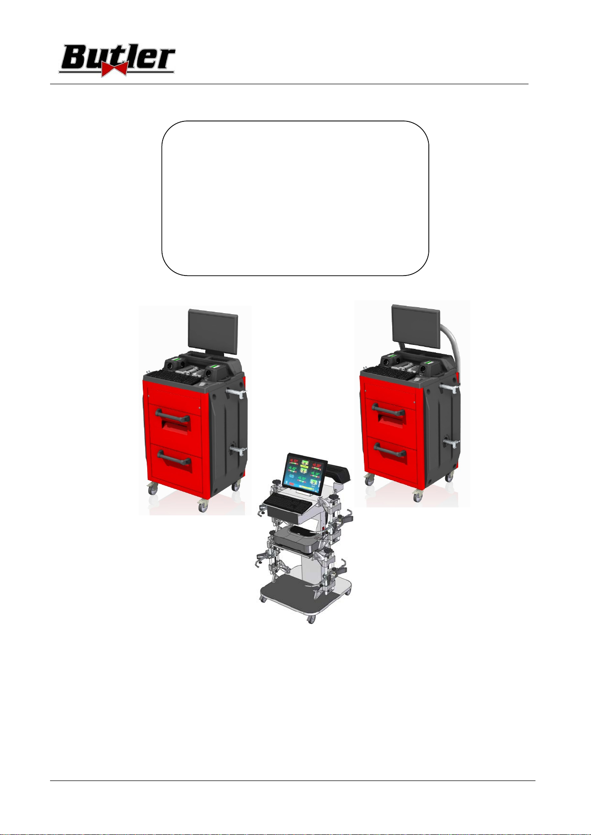
3EQUIPMENT COMPOSITION........................................................................................................................ 5
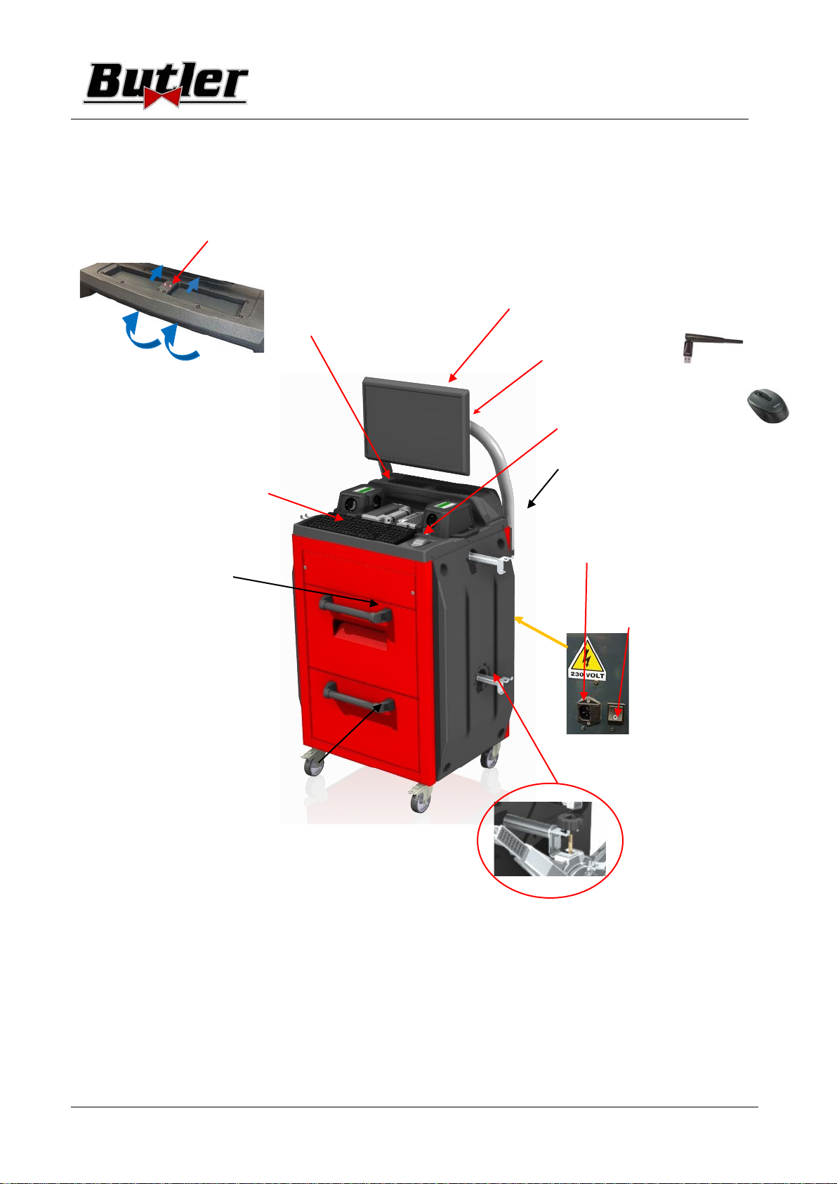
3.1 Cabinets of the Models SPEED32HPR/SPEED32HP ............................................................................... 5
3.2 Cabinets of the Models SPEED32SP ...................................................................................................... 6
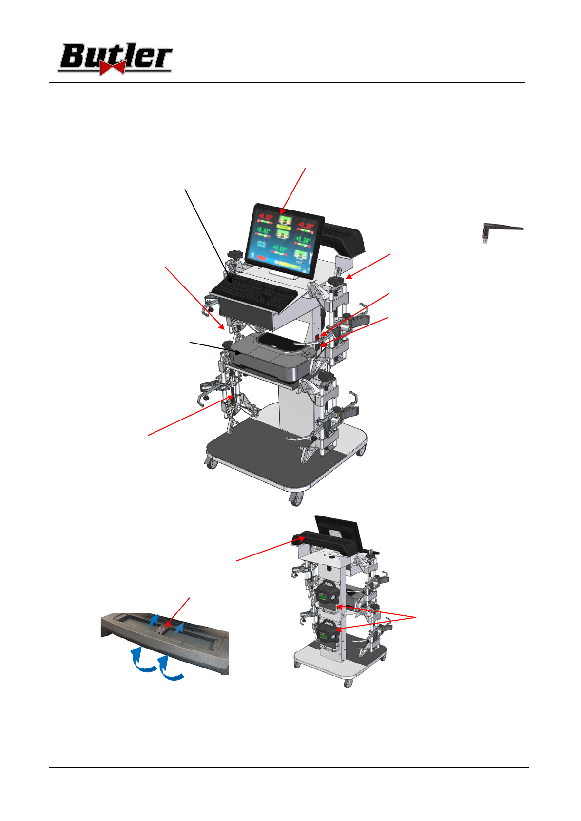
3.3 Cabinets of the Models SPEED32L ........................................................................................................ 7
3.4 Management PC .................................................................................................................................... 8
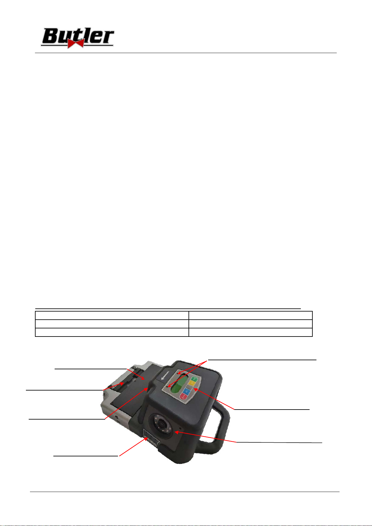
3.5 MEASURING HEADS ............................................................................................................................... 8
3.5.1 Measuring head keypads ................................................................................................................................ 9
3.5.2 LED for adjustment tollerance signalling ......................................................................................................... 9
3.6 Clamps with target ................................................................................................................................. 10
3.7 Turn plates ............................................................................................................................................. 11
3.7.1 Turn plates STDA124 (for models SPEED32HP-SPEED32HPR) ......................................................................... 11
3.7.2 Turn plates S110A7/P (for the models SPEED32SP-SPEED32L) ....................................................................... 11
3.8 Push-pedal ............................................................................................................................................. 11
3.9 Steering lock .......................................................................................................................................... 11
4EQUIPMENT CHARACTERISTICS ................................................................................................................. 12
4.1 Safety devices ........................................................................................................................................ 12
4.2 Precision measuring ranges.................................................................................................................... 12
4.3 Overall dimensions ............................................................................................................................... 12
5TRANSPORTATION AND INSTALLATION ..................................................................................................... 13
5.1 Transportaon and unpacking ............................................................................................................... 13
5.2 Installaon ............................................................................................................................................. 13
5.2.1 Electrical connecon ........................................................................................................................................ 13
5.2.2 Cabinet assembly ............................................................................................................................................. 13
5.2.3 Clamp / / Target mounng .............................................................................................................................. 14
5.2.4 Fixing of measuring head supports ................................................................................................................. 15
6SWITCHING THE EQUIPMENT ON AND OFF .............................................................................................. 17
6.1 Switching on .......................................................................................................................................... 17
6.2 Switching o .......................................................................................................................................... 17
7AUTOMATIC SWITCHING OFF OF THE MEASURING HEADS ...................................................................... 18
8FLAT BATTERY INDICATION ......................................................................................................................... 18
9PROGRAM CONFIGURATION ...................................................................................................................... 19
9.1 DATABASE Groups Conguraon ........................................................................................................... 20
9.2 Miscellaneous ........................................................................................................................................ 22
10 DIAGNOSIS AND ADJUSTMENT OF A VEHICLE ........................................................................................ 24
10.1 Presentaon page ................................................................................................................................ 24
10.2 Preliminary operaons ........................................................................................................................ 25
10.2.1 Preliminary vehicle control operaons .......................................................................................................... 25
10.2.2 Preparing for measurements ......................................................................................................................... 25
10.3 Selecng the make and model of a vehicle ......................................................................................... 27
10.3.1 “ProView” vehicle search mode .................................................................................................................... 29
10.4 Search for vehicles with plate no. with “SHOOT & GO” ...................................................................... 30

BUTLER Engineering & Marketing S.p.A. a s.u. - Via Balduina 5/7 - 42010 Rio Saliceto (RE - Italy)
Tel. +39 0522 647911, Fax +39 0522 649760 e-mail: info@butler.it / www.butler.it
P. 2/62
SPEED32HPR – SPEED32HP
SPEED32SP - SPEED32L
USER MANUAL
Code 2025-M351-00
(05/2021)
10.5 Displaying of pre-selected vehicle technical data ................................................................................. 31
10.5.1 Tyre type and tyre pressure selecon .............................................................................................................. 32
10.5.2 Display of ADDITIONAL MEASUREMENTS on CHASSIS HEIGHTS .......................................................... 33
10.5.3 Display of CHECK MEASUREMENTS on CHASSIS HEIGHTS ................................................................... 34
10.5.4 Display of images for AID in ADJUSTMENT ................................................................................................. 35
10.6 Push run-out with automac acquision .............................................................................................. 36
10.7 Preparing for measurements ................................................................................................................. 38
10.8 Aligning of the vehicle / direct measurements ..................................................................................... 39
10.9 Steering procedure ................................................................................................................................ 40
10.10 Vehicle diagnosis ................................................................................................................................. 41
10.11 Preparaon for adjustment ................................................................................................................. 41
10.12 Rear axle adjustment ........................................................................................................................... 42
10.13 Front axle adjustment ......................................................................................................................... 43
10.13.1 Steered wheels front toe Adjustment ............................................................................................................ 44
10.13.2 “Jack-Hold” Procedure................................................................................................................................. 45
10.14 Summary of the Adjustment DIAGNOSIS data .................................................................................... 46
10.14.1 "Test Drive” procedure - steering wheel alignment check ............................................................................ 47
10.15 Auxiliary funcons menu ..................................................................................................................... 48
10.15.1 Chassis diagnosis ........................................................................................................................................... 49
10.16 Prinng of measurements taken ......................................................................................................... 50
10.17 Saving of tests performed with TEq-Link ............................................................................................. 54
10.17.1 TEq-Link functionality conguration.............................................................................................................. 54
11 DATABASE CUSTOMISATION ....................................................................................................................... 55
11.1 Inseron of a new group ....................................................................................................................... 55
11.2 Deleon of a new group ........................................................................................................................ 56
11.3 Inseron of a new vehicle ..................................................................................................................... 57
11.4 Deleon of a customised vehicle .......................................................................................................... 58
12 SMARTCARD FOR PROGRAM AND DATABASE PROTECTION .................................................................... 59
12.1 DATABASE management ........................................................................................................................ 59
13 ERRORS DURING MEASURING ................................................................................................................... 60
13.1 Measuring heads data transmission / receiving error / target non-idencaon errors. .................... 60
14 PROBLEMS .................................................................................................................................................. 61
15 MAINTENANCE ........................................................................................................................................... 61
16 STORAGE AND SCRAPPING ........................................................................................................................ 62
17 MACHINE IDENTIFICATION DATA ............................................................................................................... 62

BUTLER Engineering & Marketing S.p.A. a s.u. - Via Balduina 5/7 - 42010 Rio Saliceto (RE - Italy)
Tel. +39 0522 647911, Fax +39 0522 649760 e-mail: info@butler.it / www.butler.it P. 3/62
SPEED32HPR – SPEED32HP
SPEED32SP - SPEED32L
USER MANUAL
Code 2025-M351-00
(05/2021)
0WARNINGS
Any damage resulng from failure to observe the instrucons contained in this manual and from improper use of
the machine exempts Butler S.p.A. from any responsibility.
0.1 Preliminary safety informaon
Before turning on the equipment:
• Read the instrucons and the enre manual before using or working on the wheel aligner. This manual is an
integral part of the product and is intended to provide the user with instrucons on the use of the SPEED32
wheel aligner. Therefore, keep it, for the enre operang life of the machine, in a known and easily accessible
place and consult it whenever uncertaines arise. All product operators must be able to read the manual.
• Check that the power supply complies with the specicaons shown on the plate. The plate with the voltage
and frequency data is located on the back of the equipment. Please note the informaon on the plate. NEVER
connect the appliance to a voltage or frequency other than those indicated.
•Properly arrange the power cable of the wheel aligner. This product has a built-in 3-wire plug with grounding.
It only ts into a socket with built-in grounding. If it is not possible to insert the plug into a socket of this type,
please consult an electrician. Do not modify or misuse the plug.
When the equipment is turned o:
• Do not turn o the PC, contained within the equipment, by unplugging or using the switch of the PC itself, but
use the procedure described in para.6.2 on p. 17. Incorrect shutdown of the PC can cause "corrupon" of the
les contained in the HARD-DISK.
• The shutdown procedure described in para. 6.2 on p. 17 does not intervene on the supports for recharging the
baeries, which therefore connue to be powered.
In emergency condions and before any maintenance work:
•Isolate the machine from power sources, with the appropriate main switch of the machine and remove the
plug from the power socket.
• Do not try to maintain this unit arbitrarily, as opening or removal of the doors could expose you to dangerous
voltages; maintenance intervenons must only and exclusively be carried out by authorised service personnel.
Work environment and equipment cleaning:
•The work environment must be kept clean, dry, not exposed to atmospheric agents and suciently lit.
• Avoid cleaning the equipment with jets of water and compressed air.
• To clean plasc panels or shelves, use a damp cloth (in any case avoid liquids containing solvents).
Butler S.p.A. may at any time make changes to the models described in this manual for
technical or commercial reasons.
The trademarks and are owned by Butler S.p.A.
All the remaining trademarks mentioned, the reproduced logos and the images belong to
the legitimate owners who fully hold the relevant rights.

BUTLER Engineering & Marketing S.p.A. a s.u. - Via Balduina 5/7 - 42010 Rio Saliceto (RE - Italy)
Tel. +39 0522 647911, Fax +39 0522 649760 e-mail: info@butler.it / www.butler.it
P. 4/62
SPEED32HPR – SPEED32HP
SPEED32SP - SPEED32L
USER MANUAL
Code 2025-M351-00
(05/2021)
1 INTENDED USE
The SPEED32 system is an equipment intended for detecon of all the characterisc angles of vehicles. Two-axle
cars and light commercial vehicles can be tested with wheelbase between min 1800mm and max 4700mm.
Detecon of the angles is carried out by two sensors posioned between the front and rear wheels, each with
two Megapixel cameras that idenfy the posion in space of 4 three-dimensional targets posioned on the
wheels.
The data transmission from the sensors to the cabinet takes place VIA RADIO through compable modules Bluethooth .
Temperature range for use if the equipment between 0 and 40°C.
2 TRAINING OF DESIGNATED PERSONNEL
Only specially trained and authorised personnel may use the equipment. In order to ensure machine management
are opmal and for measurements to be carried out eciently, the designated personnel must be properly trained to
learn the necessary informaon in order to achieve an operang mode that is in line with the instrucons provided by
the manufacturer. For any uncertaines relang to use and maintenance of the machine, consult the instrucon
manual of the machine or individual equipment (PC, monitor, printer ...); if in doubt, do not interpret, it is advisable
to consult the authorised service centres or the Butler S.p.A. technical assistance directly.
2.1 General prevenon measures
•During operaon and maintenance of this machine, it is absolutely essenal to comply with all the
safety and accident-prevenon regulaons in force.
•The equipment must be used only by authorised and adequately trained personnel.
• It is not allowed to store very heavy objects (weighing more than 15Kg) in the compartments inside the
cabinet, such as turntables.
•This equipment must only be employed for the use for which it is expressly designed. Butler S.p.A.
declines all responsibility for damage to persons, animals and property caused by improper use of the
machine.
•The installaon of accessories and spare parts must be performed by authorised Butler S.p.A. person-
nel and original accessories and spare parts must be used. It is also not allowed, in any way, to replace-
ments the baeries using non-original, it is necessary to use only the manufacturer’s original baery on
the heads.
•The machine must only work in places where there is no danger of explosion or re.
•The removal or modicaon of safety devices or of warning signs placed on the machine can cause seri-
ous danger and constutes a violaon of the European safety standards.
•Before carrying out any maintenance on the system, it is necessary to disconnect the power supply.
If in doubt, do not interpret, contact the Butler S.p.A. technical assistance in advance in order to receive
informaon to be able to perform operaons in condions of maximum safety.
•Prevent unauthorised personnel from approaching the wheel aligner during use.
• The operator should wear safety footwear to prevent foot damage, caused by accidental fall of clamps or
measuring heads. Use footwear with cered protecon according to the rule EN ISO 20345 standard.

BUTLER Engineering & Marketing S.p.A. a s.u. - Via Balduina 5/7 - 42010 Rio Saliceto (RE - Italy)
Tel. +39 0522 647911, Fax +39 0522 649760 e-mail: info@butler.it / www.butler.it P. 5/62
SPEED32HPR – SPEED32HP
SPEED32SP - SPEED32L
USER MANUAL
Code 2025-M351-00
(05/2021)
LEDs that indicate the charg-
ing phase of the batteries
BATTERY CHARGER SUPPORT
(the mod. HPR includes a set of
extra STDA160 batteries)
To remove the batteries, press the
internal side of the battery charging
support from below
CENTRAL COMPARTMENT
FOR PRINTER HOUSING
The results are printed with
a colour inkjet printer for A4
size sheets. The instructions
on the use and maintenance
of the printer are provided in
the manual supplied with the
printer; follow the instructions
indicated in it.
MONITOR
There is a 22”16/9 high denition colour
monitor (optionally, with the VARMON27
version, a 27” monitor is available). The
instructions on use and maintenance are
shown in the manual supplied with the
same; follow the instructions indicated in it.
USB Wi-Fi adapter
Wireless mouse and mat
(only for HPR model)
POWER SUPPLY
OUTLET
Equipment GENERAL SWITCH
(on the rear panel)
4 supports for
housing of the
clamps with target
3 EQUIPMENT COMPOSITION
3.1 Cabinets of the Models SPEED32HPR/SPEED32HP
MANAGEMENT PC HOUSING
Accessible from the rear panel. For the
characteristics of the PC see para. 3.4
p. 8
MEASURING CABINET
The measuring cabinet is used for all the
measurement operations. The cabinet is
equipped with electronic components for
processing and managing of the meas-
urements received from the sensors.
Powersupply:220/240Vac single-phase
50/60Hz Max absorbed power: 500w
PC KEYPAD
The equipment is equipped with a
102-key PC-type control keypad

BUTLER Engineering & Marketing S.p.A. a s.u. - Via Balduina 5/7 - 42010 Rio Saliceto (RE - Italy)
Tel. +39 0522 647911, Fax +39 0522 649760 e-mail: info@butler.it / www.butler.it
P. 6/62
SPEED32HPR – SPEED32HP
SPEED32SP - SPEED32L
USER MANUAL
Code 2025-M351-00
(05/2021)
LEDs that indicate the charg-
ing phase of the batteries
BATTERY CHARGER SUPPORT
CENTRAL COMPARTMENT
FOR PRINTER HOUSING
The results are printed with
a colour inkjet printer for A4
size sheets. The instructions
on the use and maintenance
of the printer are provided in
the manual supplied with the
printer; follow the instructions
indicated in it.
MONITOR
There is a 22”16/9 high denition colour
monitor. The instructions on use and
maintenance are shown in the manual
supplied with the same; follow the instruc-
tions indicated in it.
4 supports for
housing of the
clamps with target
3.2 Cabinets of the SPEED32SP Models
To remove the batteries,
press from the bottom on
the inside of the battery-
charger support
PC KEYPAD
The equipment is equipped with a
102-key PC-type control keypad
MEASURING CABINET
The measuring cabinet is used for all the
measurement operations. The cabinet
is equipped with electronic components
for processing and managing of the
measurements received from the sensors.
Power supply: 220/240 Vac single-phase
50/60Hz Max absorbed power: 500w
POWER SUPPLY
OUTLET
MAIN SWITCH
of the equipment
(on the rear panel)
MANAGEMENT PC HOUSING
Accessible from the rear panel. For the
characteristics of the PC see para. 3.4
p. 8
USB Wi-Fi adapter

BUTLER Engineering & Marketing S.p.A. a s.u. - Via Balduina 5/7 - 42010 Rio Saliceto (RE - Italy)
Tel. +39 0522 647911, Fax +39 0522 649760 e-mail: info@butler.it / www.butler.it P. 7/62
SPEED32HPR – SPEED32HP
SPEED32SP - SPEED32L
USER MANUAL
Code 2025-M351-00
(05/2021)
PC KEYPAD
The equipment is equipped with a 102-key PC-type
control keypad.
UPPER COMPARTMENT FOR
MANAGEMENT PC HOUSING
For the characteristics of the PC
see para. 3.4 p. 8
CENTRAL PLANE FOR PRINTER
HOUSING
The results are printed with a colour
inkjet printer for A4 size sheets. The
instructions on the use and mainte-
nance of the printer are provided in
the manual supplied with the printer;
follow the instructions indicated in it.
4 supports for
housing of the clamps
with target
There is a 22”16/9 high denition colour monitor.
The instructions on use and maintenance are
shown in the manual supplied with the same;
follow the instructions indicated in it.
Equipment GENERAL SWITCH
POWER SUPPLY OUTLET
MEASURING CABINET
The measuring cabinet is used for
all the measurement operations. The
cabinet is equipped with electronic
components for processing and man-
aging of the measurements received
from the sensors. Power supply: 220 /
240 Vac single-phase 50/60Hz
Max absorbed power: 500w
LEDs that indicate the charg-
ing phase of the batteries
3.3 Cabinets of the SPEED32L Models
Battery charging support
To remove the batteries, press
from the bottom on the inside of
the batterycharger support
MONITOR
Positioning of the
measuring heads
USB Wi-Fi adapter

Power supply NiMH baery (Nickel-Metal Hydride) 12V- 4Ah
Average operaon with baery in full eciency and charged Approximately 8 hours
Average charging me Approximately 12 hours
BUTLER Engineering & Marketing S.p.A. a s.u. - Via Balduina 5/7 - 42010 Rio Saliceto (RE - Italy)
Tel. +39 0522 647911, Fax +39 0522 649760 e-mail: info@butler.it / www.butler.it
P. 8/62
SPEED32HPR – SPEED32HP
SPEED32SP - SPEED32L
USER MANUAL
Code 2025-M351-00
(05/2021)
Bracket to connect it to
the lifter (see para. 5.2.4
and 10.2.2)
Tolerance signalling LED
(see para. 3.5.1 on p. 9
DETECTOR KEYPAD
(see para. 3.5.1 p. 9)
Megapixel camera
with I.R. LED illuminators
3.4 Management PC
The soware is installed on the management PC (personal computer), located inside the cabinet.
The management PC has the following minimum features:
•Processor 2.00 GHz
•RAM 4 Gb;
•Smart card reader
•6 USB; 1 LAN Ethernet 10/100/1000 Mb;
•Integrated Windows 10 IoT ™ operang system, standard operang system in English
•Screen output 1366x768 Pixels HD Ready
• Hard Disk ≥ 64.0 Gb
3.5 MEASURING HEADS
The measuring heads of the 3D equipment do not require the connecon of any cables or cords for measuring
angles or for data transmission.
The detecon groups consist of 2 megapixel cameras for each measuring head. Each camera has a group of high
eciency infra-red eming LEDs, which act as illuminators for the 3D targets
posioned on the wheels of the vehicle.
The measuring heads communicate directly with the cabinet. Data transmission takes place VIA RADIO through
compables modules Bluetooth contained within the heads and cabinet.
The characterisc angles of both vehicle axles are controlled and compensated by 2 side cameras and 2
electronic inclinometers posioned inside the two measuring heads.
Power is supplied by long-lasng 12V rechargeable baeries. The baeries are recharged when they are inserted
in the charging support located on the cabinet (see para. 3).
Note: together with the measuring heads package, there is a leaet cod. 2025R37800 with warnings on baery
use and maintenance.
ATTENTION: When the baery is removed and/or inserted, always turn o the measuring head; it can be turned o
manually by simultaneously pressing the external red and green buons (see para. 3.5.1).
The power and consumpon data of the measuring heads with rechargeable baery is the following
BATTERY
to remove the battery,
press from below
GREEN LED: battery charging/external power supply
RED LED: signalling the detector is on
Figure 1
Side cameras for
compensation of
reciprocal angles

KEYS DESCRIPTION
Head ignion key.
Pressed simultaneously they manually switch o
the head.
BUTLER Engineering & Marketing S.p.A. a s.u. - Via Balduina 5/7 - 42010 Rio Saliceto (RE - Italy)
Tel. +39 0522 647911, Fax +39 0522 649760 e-mail: info@butler.it / www.butler.it P. 9/62
SPEED32HPR – SPEED32HP
SPEED32SP - SPEED32L
USER MANUAL
Code 2025-M351-00
(05/2021)
LED on the
FRONT SIDE
ICAMBER/CASTER tolerance
(bring the "R" selecon symbol to the desired angle)
TOE Tolerance
LED on the
REAR SIDE
CAMBER Tolerance
TOE Tolerance
3.5.1 Measuring head keypads
(B) Red LED
Figure 2
(A) Green LED
Alphanumeric display
- Indicates the battery status in %
Key of Figure 2:
A - • Green LED: Not used. Power is supplied by cable and the baery (if present) is
charging
B - • Red LED on steady: The measuring head is on
• Red LED ashing (fast): The measuring head is turning on
• Red LED ashing (slow): The measuring head baery is low (when the remaining
baery charge is lower than or equal to 30%); it will turn
o aer a few minutes
3.5.2 LED for indication of tollerance in adjustment
The measuring heads are equipped with side-mounted red/green LED indicators (see para.3.5).
During the detecon phases of the angles, these are simply switched on intermiently, to indicate the operaon
of the measuring devices.
Only for the models of the SPEED32HP and SPEED32HPR series, during the adjustment phase they report the
values in tolerance.
Tolerance indicator during adjustment
•GREEN LED ashing the measurement is in tolerance exactly in the centre
•RED LED ashing together with the GREEN LED steady the measurement is within tolerance
•RED LED on the measurement is NOT in tolerance
NOTE: The Toe-in tolerance is always indicated on the lower LED row.
During rear adjustment, the camber is always indicated on the upper row of LEDs
During the front adjustment, both the camber and the caster can be indicated on the upper LED row. The "R" selecon
symbol should be set on the desired value (see 10.13 on p. 43).

BUTLER Engineering & Marketing S.p.A. a s.u. - Via Balduina 5/7 - 42010 Rio Saliceto (RE - Italy)
Tel. +39 0522 647911, Fax +39 0522 649760 e-mail: info@butler.it / www.butler.it
P. 10/62
SPEED32HPR – SPEED32HP
SPEED32SP - SPEED32L
USER MANUAL
Code 2025-M351-00
(05/2021)
position code
(FL = FRONT
LEFT)
Figure 4
3.6 Clamps with target
Included are 3 dierent types of clamps, where the target ts.
They are all of the self-centring type, including removable claws.
SPEED32L.4
SPEED32SP.4
4-point self-centering holding
clamps, complete with target (for
rims from 10’’ to 24’’)
SPEED32L.4
SPEED32SP.4
4-point self-centering resting clamps,
complete with target (for rims from 10”
to 24”)
SPEED32L.3
SPEED32SP.3
SPEED32HPR.3
SPEED32HP.3
3-point self-centering holding clamps,
complete with target (for rims from 8”
to 24”)
Figure 3
They are marked Front Le and Right and Rear Le and Right, according to the following table (See Figure 4):
FL = FRONT LEFT
FR = FRONT RIGHT
RL = REAR LEFT
RR = REAR RIGHT
Aenon: the inclinaon of the targets is determined at the me of installaon, as described in paragraph
5.2.3.
Once the target has been mounted, during the procedure, it is only required to fasten the clamps taking care to
posion them approximately vercally (see gures above).
Each target also has a barcode that describes the characterisaon of the 3D object in space.
The clamp + target calibraon and progressive producon number for traceability are also contained in the afore-
menoned code. 3D object characteri-
sation in space
Graphic symbol sticker illustrating
the position (See para. 5.2.3), ap-
plied both on the target and on the
clamp.
In the SPEED32HPR models, the targets are supplied with spirit levels (code
STDA149) that allow correct mounting of the clamps with precise and simple
orientation of the target.

BUTLER Engineering & Marketing S.p.A. a s.u. - Via Balduina 5/7 - 42010 Rio Saliceto (RE - Italy)
Tel. +39 0522 647911, Fax +39 0522 649760 e-mail: info@butler.it / www.butler.it P. 11/62
SPEED32HPR – SPEED32HP
SPEED32SP - SPEED32L
USER MANUAL
Code 2025-M351-00
(05/2021)
3.9 Steering lock
It is a tool used to hold the steering in a xed posion. It is used
before the adjustment procedure as shown in the instrucons that
appear during the program.
PLATE STOP
PLATE SEAT LEVELLING SUPPORT
DEVICE
UPPER PLATE WITH ANTI-SLIP
DISC
PLATE STOP
UPPER PLATE WITH ANTI-
SLIP DISC
3.7 Turn plates
3.7.1 Turn plates STDA124 (for models SPEED32HP-SPEED32HPR)
The STDA124 turn plates have a plate with a 360 mm diameter.
3.7.2 Turn plates S110A7/P (for the models SPEED32SP-SPEED32L)
The turn plates S110A7/P have a plate diameter of 310 mm
PLATE SEAT
LEVELLING SUP-
PORT DEVICE
3.8 Push-pedal
It is a tool used to lock the brake pedal during measurement pre-
liminary preparaon operaons. It is to be used as shown in the
instrucons that appear during the program.

Axis Measurement Precision Measuring range Total measuring
range
Front
Toe ±2’ ±2° ±20° x 2
Semi-toe ±1’ ±1° ±20°
Set-Back ±2 ±2° ±5°
Camber ±2’ ±3° ±10°
Caster ±5’ ±10° ±18°
King-Pin ±5’ ±10° ±18°
Rear
Toe ±2’ ±2° ±20° x 2
Semi-toe ±1’ ±1° ±20°
Set-Back ±2’ ±2° ±5°
Camber ±2’ ±3° ±10°
Thrust angle ±2’ ±2° ±5°
BUTLER Engineering & Marketing S.p.A. a s.u. - Via Balduina 5/7 - 42010 Rio Saliceto (RE - Italy)
Tel. +39 0522 647911, Fax +39 0522 649760 e-mail: info@butler.it / www.butler.it
P. 12/62
SPEED32HPR – SPEED32HP
SPEED32SP - SPEED32L
USER MANUAL
Code 2025-M351-00
(05/2021)
4 EQUIPMENT CHARACTERISTICS
4.1 Safety devices
The wheel aligner is equipped with a safety device (main switch) located on the rear of the machine, see chap. 3
on p. 5. The main switch deacvates the power supply of the machine when placed in the "0" posion.
4.2 Precision measuring ranges
4.3 Overall dimensions
SPEED32HPR/ SPEED32HP SPEED32SP SPEED32L
Figure 5

BUTLER Engineering & Marketing S.p.A. a s.u. - Via Balduina 5/7 - 42010 Rio Saliceto (RE - Italy)
Tel. +39 0522 647911, Fax +39 0522 649760 e-mail: info@butler.it / www.butler.it P. 13/62
SPEED32HPR – SPEED32HP
SPEED32SP - SPEED32L
USER MANUAL
Code 2025-M351-00
(05/2021)
5 TRANSPORT AND INSTALLATION
5.1 Transport and unpacking
The machine is supplied packed in a box secured onto a pallet to facilitate transportaon. To transport the machine
to the point where it will be installed, use liing and transport means such as forklis or lis with forks.
The machines must be stored packed in a dry and venlated place (permied temperature -25° + 55°C).
The packaging must never be overturned or arranged horizontally, the pallet must always rest on a at and solid
surface, do not stack other packages on top, the arrangement must allow easy reading of the indicaons.
DURING UNPACKING ALWAYS WEAR GLOVES TO AVOID POSSIBLE INJURIES CAUSED BY CONTACT WITH THE PACK-
AGING MATERIAL (NAILS, ETC.).
Be sure to have received all the standard parts listed above.
The packaging material (plasc bags, polystyrene, nails, screws, wood, etc.) must be collected and disposed of ac-
cording to the regulaons in force, with the excepon of the pallet, which could be reused for subsequent handling
of the machine.
5.2 Installaon
Install the machine in a dry, covered, suciently lit place, possibly enclosed or in any case protected from atmos-
pheric agents. Before posioning the equipment, make sure that the chosen locaon is suitable for the regulaons
in force on workplace safety and check the minimum distances from walls or other obstacles.
5.2.1 Electrical connection
Before connecng the machine, check carefully:
•that the characteriscs of the power line correspond to the requirements of the machine indicated on the rela-
ve plate;
•that the grounding line is present and that it is adequately sized (secon greater than or equal to the maximum
secon of the power cables);
•that all the components of the power line are in a good condion;
Connect the machine to the mains using the supplied 3-pole plug (230V single-phase) to the socket on the wall. If
the plug supplied is not suitable for the one on the wall, equip the machine with the plug in accordance with the
local laws and current standards and regulaons. This operaon must be performed by experienced and qualied
personnel.
5.2.2 Cabinet assembly
The assembly of the cabinet of the SPEED32HPR, SPEED32HP and SPEED32SP models, consists of xing the monitor
and posioning the PC and printer in their housing (see chap. 3 on page 5).
The assembly of the cabinet of the SPEED32L models, instead, is illustrated in the specic instrucon, which is sup-
plied with the equipment.

BUTLER Engineering & Marketing S.p.A. a s.u. - Via Balduina 5/7 - 42010 Rio Saliceto (RE - Italy)
Tel. +39 0522 647911, Fax +39 0522 649760 e-mail: info@butler.it / www.butler.it
P. 14/62
SPEED32HPR – SPEED32HP
SPEED32SP - SPEED32L
USER MANUAL
Code 2025-M351-00
(05/2021)
Fixing
dowel
Spoke positioned
at 12 o’clock
Inclined target
~ 20°
Fixing
dowel
Inclined target
~ 20°
Spokes positioned
at 12 o’clock
5.2.3 Clamp / Target mounting
The targets must be mounted on the clamps and oriented at approximately 20°. To perform this with preci-
sion, use the procedure described below.
Mount the targets on the clamps oriented approximately 20°, as shown above, and place them all on a vehicle.
N.B. Be sure to mount the clamps with the spokes strictly vercal (12 o’clock), as in the gure above.
Select the “target mounng” opon in the “Conguraon” menu item.
As soon as the targets are aached and opmised, the screen shown in the gure below appears.
Carefully orient the 4 targets by aligning the arrow with the target posioned above. If one or more targets are
not correctly oriented, the symbol “X” appears (see example in the rear right clamp).
Apply the two sckers provided for each clamp/target group, idenfying the front
le (FL), front right (FR), rear le (RL) and rear right (RR) posions.
See Figura 4 on page 10
Figure 6

BUTLER Engineering & Marketing S.p.A. a s.u. - Via Balduina 5/7 - 42010 Rio Saliceto (RE - Italy)
Tel. +39 0522 647911, Fax +39 0522 649760 e-mail: info@butler.it / www.butler.it P. 15/62
SPEED32HPR – SPEED32HP
SPEED32SP - SPEED32L
USER MANUAL
Code 2025-M351-00
(05/2021)
Drill 3 holes Ø 6.80 mm and thread M8 as in
the drawing below. The holes must be drilled
22.5 mm below the level of the li.
The upper edges of the sup-
ports are 6 mm lower than the
level of the li
5.2.4 Fixing of measuring head supports
It is necessary to drill 3 holes for M8 screws on each side of the li, in order to x the supports of the measuring
heads, making sure that the distance from the centre of the heads to the centre of the turn plates is 1150 mm.
If it is necessary to measure vehicles with a very long wheelbase, it is possible to move the plates forward by a
further 400 mm. The maximum distance from the rear wheels to the centre of the heads is 3150 mm.
Note: Be sure to drill the holes at a distance of 1150mm on both sides of the li.
The level of the heads must then be adjusted
through the two M5 dowels arranged on the brack-
ets. This operaon will be performed using the read-
ings in the appropriate test menu (see the "Service"
instrucons reserved for the authorised installer)
Figure 7

BUTLER Engineering & Marketing S.p.A. a s.u. - Via Balduina 5/7 - 42010 Rio Saliceto (RE - Italy)
Tel. +39 0522 647911, Fax +39 0522 649760 e-mail: info@butler.it / www.butler.it
P. 16/62
SPEED32HPR – SPEED32HP
SPEED32SP - SPEED32L
USER MANUAL
Code 2025-M351-00
(05/2021)
The 3D system can measure cars and vans with two axles and with pitches from 1800 mm to 4700 mm; and
with track between 1200 mm and 2600 mm
For vehicles with small and medium
wheelbase, place the turn plates at
normal distance from the head (distance
between heads / front target 1150 mm)
For very long wheelbase vehicles:
Posion the turn plates away from
the head (distance between heads
/ front target 1550 mm)

6SWITCHING THE EQUIPMENT ON AND OFF
ATTENTION: Before turning on the equipment, make sure that the SMART CARD for
enabling of the program and of the database is inserted in the appropriate reader on
the front of the PC. See chap. 12.
6.1 Switching on
To turn the equipment on and to be able to access the program, it is necessary to use the dedicated switch located
on the back of the unit.
At the end of the PC inializaon process, using the Windowsoperang system, the program is automacally
acvated and the presentaon page is displayed on the monitor from here it is possible to acvate all the funcons
of the equipment (see para. 10 on p. 24).
DETECTOR KEYPAD PC KEYPAD DESCRIPTION
Acvates the switch o proce-
dure of the equipment
BUTLER Engineering & Marketing S.p.A. a s.u. - Via Balduina 5/7 - 42010 Rio Saliceto (RE - Italy)
Tel. +39 0522 647911, Fax +39 0522 649760 e-mail: info@butler.it / www.butler.it P. 17/62
SPEED32HPR – SPEED32HP
SPEED32SP - SPEED32L
USER MANUAL
Code 2025-M351-00
(05/2021)
6.2 Switching o
From the presentaon page (see para. 10 on p. 24) it is possible to turn o the equipment by selecng the ap-
propriate buon.
Figure 9
Figure 8

DETECTOR KEYPAD PC KEYPAD DESCRIPTION
Deletes.
Returns to the presentaon
page. (para. 10 on p.24)
Denive conrmaon of
switching o
of the equipment
BUTLER Engineering & Marketing S.p.A. a s.u. - Via Balduina 5/7 - 42010 Rio Saliceto (RE - Italy)
Tel. +39 0522 647911, Fax +39 0522 649760 e-mail: info@butler.it / www.butler.it
P. 18/62
SPEED32HPR – SPEED32HP
SPEED32SP - SPEED32L
USER MANUAL
Code 2025-M351-00
(05/2021)
LEFT MEASURING
HEAD DEPLETED
Then turn o the equipment using the switch located on the back.
ATTENTION: The shutdown procedure does not aect the supports for recharging of the baeries,
which therefore connue to be powered.
7 AUTOMATIC SWITCHING OFF OF THE MEASURING HEADS
The system makes sure that the measuring heads turn o when the PC is turned o from the presentaon page.
However, the measuring heads switch o automacally aer approximately 5 min. if they do not receive data (e.g.
the cabinet is o).
However, they can always be switched o manually (see para. 3.5.1 on p. 9) when they are not being used.
8 FLAT BATTERY INDICATION
The system displays a low baery warning (Figure 10).
This signal is also given on the sensor itself with ashing of the red power LED (see para. 3.5.1 on p. 9).
When the residual charge is LOWER OR EQUAL to 30%; the program displays the low baery warning page (Figure
10). The head will turn o aer a few minutes. Avoid this situaon by always placing the baeries in charge as
soon as possible.
To exit the error report page, press the F1 key .
Figure 10
This manual suits for next models
9
Table of contents
Other Butler Wheel Balancer manuals