BWT Disinfecton User manual

1
BW T Disinfecton
On site production of disinfection liquid
Installation and Operating manual EN

2
Table of Contents
Safety Instructions......................................................................4
Qualifications of installer and operator...............................................................................................4
Generally Safety instructions .............................................................................................................4
General Information...................................................................5
Neuthox .........................................................................................................................................5
The BWT Disinfection .......................................................................................................................5
Application .....................................................................................................................................6
Improper Operating Methods............................................................................................................7
Warranty........................................................................................................................................7
Nameplate......................................................................................................................................7
Type Key ........................................................................................................................................8
Product overview.......................................................................9
Electrical cabinet ..........................................................................................................................9
Hydraulic cabinet .........................................................................................................................9
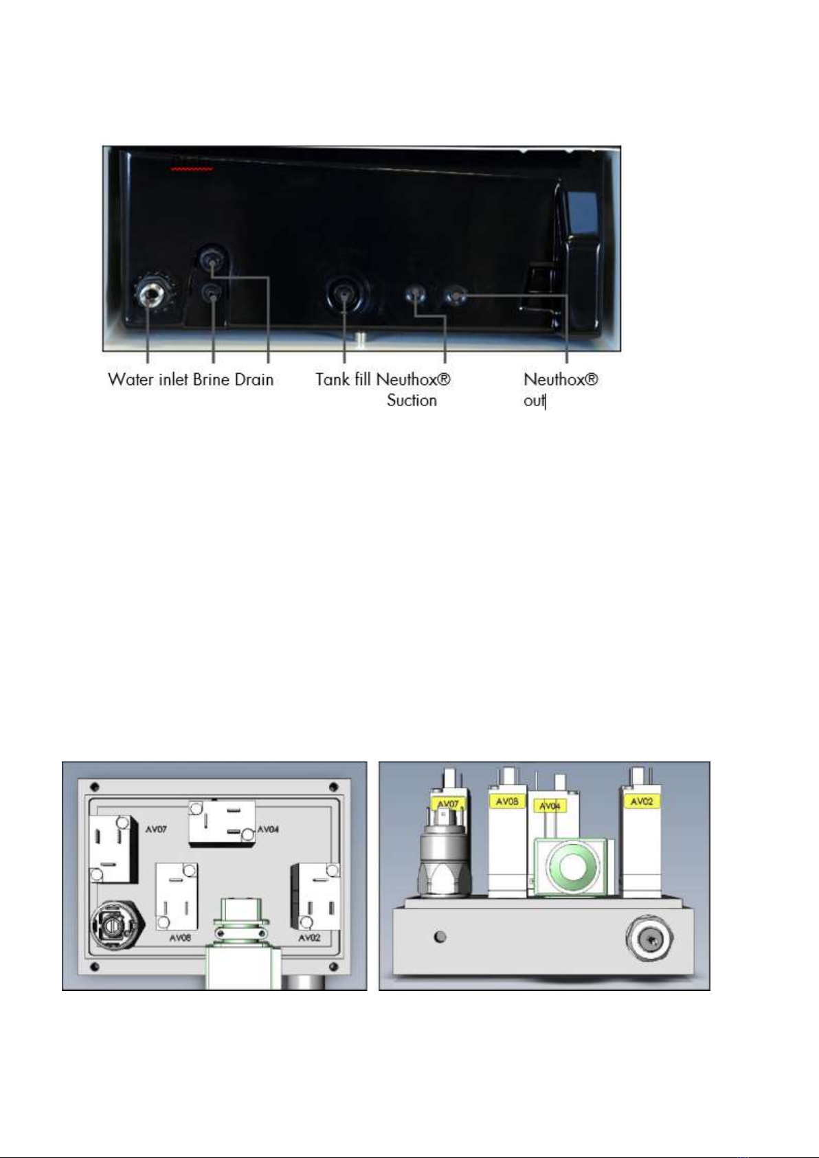
Connections...............................................................................................................................10
Valve block................................................................................................................................10
Technical Data..........................................................................12
Assembly and Installation ........................................................13
Electrical Connection......................................................................................................................13
Check valve ..................................................................................................................................13
Brine tank .....................................................................................................................................13
Connecting the brine filter ...........................................................................................................14
Neuthox tank ................................................................................................................................14
Dosing Pump.................................................................................................................................15
Dosing connector...........................................................................................................................15
Water meter..................................................................................................................................15
Communication .............................................................................................................................15
Ethernet Modbus ........................................................................................................................15
SMS communication ...................................................................................................................15
Neuthox production configurations ..........................................15
Softener settings.............................................................................................................................16
Brine pump start up.....................................................................................................................16

3
Neuthox dosing configurations.....................................................................................................16
Configuration.............................................................................................................................16
Parameters.................................................................................................................................16
Dosing settings ...........................................................................................................................16
Dosing regulator control ..............................................................................................................17
Water .......................................................................................................................................17
Start-up......................................................................................................................................17
Neuthox dosing for Proportional dosing........................................................................................18
Troubleshooting .......................................................................20
List of Alarms and troubleshooting ...................................................................................................20
Spare part list ..........................................................................26
Options:...................................................................................26
Spare part drawings................................................................27
PI-diagram...............................................................................28
Arrangement drawing ....................................................................................................................29
Disposal .......................................................................................................................................30
Declaration of Conformity ........................................................32
Noter .......................................................................................33

4
Safety Instructions
This manual contains general instructions that must be read before installation, operation and maintenance
of the machine. It must be read by both the installer and the operator, prior to installation and start-up, and
must always be available at the installation location.
This manual uses the following markings:
Warning
If these warnings are not adhered to, it might result in personal injury
Caution
If these safety instructions are not adhered to, it might result in
malfunction and damage to the machine and/or installation
Note
If these notes are adhered to, it will make installation and maintance
easier.
Qualifications of installer and operator
The installer must be sufficiently qualified to install the machine and must adhere to the local standards
regarding the electrical and hydraulic installation.
The operator must be sufficiently trained in the workings of the machine, with emphasis on the safety
instructions in this manual.
If the safety instructions are not followed, it might lead to personal injury and result in loss of warranty.
Generally Safety instructions
The safety instructions given in this manual and any existing local legislation on health protection must be
adhered to.
Always disconnect the water and power supply before working inside the machine. The machine forms small
amounts of hydrogen as a by-product of disinfection fluid production. Inadequate ventilation can lead to an
explosive atmosphere. The water quality must meet drinking water specifications –if this is not adhered to,
the softener and cell can be damaged. Neuthox® and residual chloride can become corrosive at high
concentrations –beware of material specifications in application.

5
General Information
The BWT Disinfecton is an on-site disinfection liquid producing system. Through the electrolysis of salt water, using
patented membrane cell technology, it produces a safe, cost effective, environmentally friendly nonhazardous
disinfection fluid. This unique disinfection fluid is produced under the registered name Neuthox®. Neuthox®
contains hypochlorous acid which is a highly potent oxidant. This means Neuthox® can be used as a biocide
whenever bacteria in water needs to be controlled.
Electrolysis in chemistry is the method, where an otherwise non-spontaneous process is driven by applying a direct
current. When creating Neuthox®, the machine utilizise this to split chlorine (Cl) from Sodium (Na), in ordinary
kitchen salt (NaCl).
Neuthox
Neuthox is a non-hazardous disinfectant. It has a neutral pH value of pH 5,5 - 8,5. The main components in
Neuthox is free chlorine, hypochlorous acid and sodium. For further information please read the Safety data
sheet for Neuthox.
The BWT Disinfection
The machine comes with a integrated water softener system to avoid lime scale in the cell. The production
process is carefully controlled by the build-in BWT controller/HMI to supply a uniform product with the
lowest possible residual chlorides, all the time!

6
A simplified P&I diagram shows the process. Water enters the machine through the prefilter and then the built-in
filter and the lime scale/calcium is removed in the water softener. The now soft water flow is reduced to
accommodate the cell capacity and brine is mixed into the water before it enters the electrolysis cell.
What makes Neuthox®special is that all the fluid is exposed to both sides of the cell. First the fluid passes the
negative cathode and afterwards the positive anode. By never splitting the flow, the risk of creating chlorine gas
is eliminated. Furthermore, the final product is 8.5 pH –close to pH neutral.
Application
Neuthox® is an effective biocide in multiple applications, where water quality is the key factor. It is applicable in
the areas listed below:
Dental Clinics
Medical Schools
Cooling towers
Swimming pools
Hot and cold-water systems
Drinking water disinfection
Cooling towers
BWT’s engineering staff can advise you on all application matters.

7
Improper Operating Methods
The BWT Disinfecton should be located in a frost-free and well-ventilated room.
If the BWT Disinfecton is located in a small confined space without adequate ventilation, it is necessary to fit
an exhaust system, which our BWT staff will be able to advise you on.
Warran
ty
A
guarantee claim in accordance with our general terms of sale and delivery is only valid if the following
requirements are fulfilled:
The BWT Disinfecton is used in accordance with the information within this manual.
The machine is correctly handled.
The maintenance is carried out by authorized and qualified BWT personnel.
Original BWT spare parts are used for repairs during maintenance.
Nameplate
Example of nameplate, with type- and serial number, rated
electrical and hydraulic data used for installation and CE mark of
approval.
Warning
The machine forms small amounts of hydrogen as a by-product. Inadequate
ventilation can lead to an explosive atmosphere
Warning
The machine is not approved for operation in potentially explosive
atmospheres.

8
Type Key

9
Product overview
Electrical cabinet
Hydraulic cabinet

10
Connections
Hoses must be cut with a sharp blade to ensure that it stays round, do not use a tool that deforms the hose
in any way.
Valve block
The integrated valve block contains four valves, a brine pump and a pressure switch. The valve block distributes
water and brine through the machine. The brine pump is used for both Neuthox® production and softener
regeneration. The valves are marked individually on the block.
AV02, Cell inlet valve (NC)
AV04, Drain valve (NO)
AV07, 3/2-way valve (directs flow to production process when inactive)
Switches water flow between production- and regeneration process
AV08, Tank fil valve (NC)

11
The connections in the bottom of the block are marked with both abbreviations and colored marking
rings. The colored rings correspond to the color of the hoses inserted.
W: Water (6 mm blue hose): Hard water inlet from the inlet filter.
TS: To Softener (6 mm yellow hose): Hard water to the softener.
FS: From Softener (6 mm red hose): Soft water from the softener.
TF: Tank Fill (4 mm yellow hose): Soft water for filling the brine tank.
D: Drain (6 mm hose): Water from softener regeneration process.
B: Brine (4 mm clear hose): Brine inlet from brine tank.
WB: Water and Brine (6 mm clear hose): Outlet of soft water and brine for the cell.
The flow is controlled by two flow restriction inserts mounted in a individual banjo bolt on the left side of the
block. The banjo bolts are marked with colored marking rings to tell them apart from each other.
Yellow: flow restrictor for production process
Red: flow restrictor for regeneration process.

12
Technical Data
BWT Disinfecton
Neuthox Production Capacity
(±10%)
L/h*
9
Chloride Content in Neuthox®
mg/L*
980
Free Active Chlorine
ppm*
500
pH-value
pH*
8.5
Approx. NaCl Consumption
Max.
Kg/day**
0.4
Pre-fuse
A
13
Max. Power Consumption
W
380
Voltage
V
200 - 240 VAC (±10%); 50/60 Hz
Length of Power Supply Cable
m
3
Enclosure Class, Electrical
Cabinet
IP54
Required Water Pressure at 15
L/min
Bar
1.5 –6,2 bar
Max. Drain Back Pressure
Bar
0.2
Ambient Temperature Tolerance
Min
°C
5 < 40
Required Room Ventilation
m3/h
7
Recommended Running Hours
h/day
15
Maximum Running Hours
Water
h/day
20
Connection Hose Length
Water
m
1.3
Connection (BSP Male) Inlet
″
1/2″
Connection (Push-in) Drain
mm
6
Drain Hose - min. inner
diameter
mm
4
Drain Hose - max. length
m
5
Dosing Pump
No
Max. Flow Rate
L/h
-
Max. Pressure
Bar
-
Suction Head
mWg
-
Dimensions
Width
mm
560
Height
mm
1540
Depth
mm
485
Weight
Kg
63?
Brine Tank Capacity
L
33
Neuthox tank Capacity
L
33
Sound Pressure
dB(A)
51
* Production is dependent on mechanical flow valve and is subject to variation (± 10%)
** Free available chlorine is dependent on each individual cell and is subject to variations (± 10%)
*** Salt consumption is calculated from empirical data and is subject to variations
**** Always supply power through a residual current circuit breaker

13
Assembly and Installation
Electrical Connection
Make sure that the supply voltage is the same as specified on the machine.
The BWT Disinfecton is supplied with 230V, 50Hz via a CEE plug, for easy connection to the power supply.
Check valve
The water supply for the BWT Disinfecton requires installing of a Medium Category 2 non-return valve with
sampling. Controllable non-return valve (Type EA according to DS / EN-1717)
The machine has a male 'A” BSP connection for water inlet located in the bottom of the cabinet. The water
supply should be of potable quality, containing less than 0.5 mg/l iron and less than 0.1 mg/l manganese.
The supply pressure and drain backpressure must be within the limits stated in the technical data. Low water
supply pressure and high drain backpressure can increase the precision of the flow valves.
The machine flushes water from the regeneration process to the drain. The drainage from the machine consists of
saline water with a high calcium content. Connect the drain hose to the machine with the push in fitting in the
bottom of the machine. Place the other end in an appropriate outlet.
6mm hose; drainage from machine
See section: Connections for picture of machine connections.
The water pressure should be at minimum 1,5 bar, and the back pressure in the
drain should not be more than 0,2 bar. The water supply must meet the drinking
water specifications 98/83/EC –if this is not adhered to the softener and cell
can be damaged.
Brine tank
Place the brine tank on the left side, below the machine. The two hoses on the backside of the tank is
connected to the machine, through the push-in fitting directly above them.
4 mm clear hose; brine to machine
4 mm yellow hose; soft water refilling of brine tank
Warning
Caution

14
The brine tank comes standard with 10 kg of salt for commissioning the machine. 25 kg of salt should be
added subsequently, to fill the brine tank. The level of salt must be above water level. No water should be
visible. The salt needs some time to dissolve, in order to saturate the water.
See section: Connections for picture of machine connections.
The brine tank level sensor plug is connected to the machine via the M8 circular plug hanging on the left side
of the cabinet, next to the drip tray. The excess wire can be bundled behind the tank.To avoid waiting time for
the initial filling of soft water, bring five liters of water for commissioning the machine.
Bring 5L for start-up to avoid unnecessary waiting time.
The tank must be supplied with water from the softener during the process to avoid
lime scale in the cell.
Connecting the brine filter
The hose for the brine filter is taped to the bottom of the BWT Disinfecton.
1. Pull hose through lid.
2. Pull hose through grey square.
3. Unscrew filter and pull hose through black fitting, leave a 30mm gap between the bottom of the filter
and the bottom end of the hose.
4. Insert hose in filter and screw filter back on.
5. Activate manual regeneration of softener on the Sequence control menu.
Neuthox tank
Place the Neuthox tank on the right side, below the machine. Connect the supplied 6 mm black hose to the
machine, through the hole in the plastic spill tray, into the Neuthox®outlet push-in fitting on the cell. Place the
other end of the hose in the Neuthox tank.
Hose entry fitting must be horizontal to avoid leakage (connections should be from the bottom to ensure that
the support for the hose is properly seated).
See section: Connections for picture of machine connections.
The Neuthox tank level sensor plug is connected to the machine via the M8 circular plug hanging from the
cabinet’s right side, next to the drip tray. The excess wire can be bundled behind the tank.
Note
Caution

15
Dosing Pump
The BWT Disinfecton is equipped with an internal dosing pump, which is governed by the controller, based
on the pulses from the water meter. Connect the supplied 6 mm clear, soft PVC hose, through the designated
hole in the plastic spill tray, to the fitting on the suction side of the pump.
Place the other end of the hose at the bottom of the Neuthox tank and install the supplied foot valve.
Dosing connector
The dosing connector has a 1/2 "external thread. The dosing connector contains a shortened internal check
valve. This means the tube can be seated in the middle of the pipe. It can be installed in all directions.
Water meter
To prevent overdosing during low water usage pulses from a water meter is recorded in the controller/HMI
and dosing stopped if water consumptions drops below specified values entered in the controller/HMI. The
2-lead cable from the water meter is connected directly to the terminals inside the cabinet. If the water meter
uses a transistor output be aware of polarity.
See the electrical diagram for more information.
Communication
A communication system can be connected to the BWT Disinfecton.
Ethernet Modbus
If the machine is equipped with an Ethernet card, communication via Modbus TCP/IP or Remote Access
(Unitronics freeware) is possible. Connect to the unit via the RJ45 plug on the side of the cabinet.
SMS communication
If the machine is equipped with a Modem for mobile phone messages. Insert
a SIM card into the modem
Neuthox production configurations

16
Softener settings
For the controller/HMI to calculate the time between regeneration, the local water hardness must be entered in
the controller/HMI at the softener settings. The local water hardness can be measured with the hardness
measuring kit supplied with the machine.
1. Fill the test tube with water up to 10ml.
2. Add 2 drops of solution A into the test tube.
3. Carefully shake tube to incorporate. The water should now turn purple red.
4. Add 1 drop of solution B while carefully shaking tube.
5. Continue adding drops and shaking, until the color of the water changes.
6. The added number of drops of solution B until a color change indicates the hardness of the water in
°dH.
Brine pump start up
The air in the hose between the brine tank and the brine pump must be pumped out of the system. Go to
Sequence control menu and run a manual regenerating process. This will ensure that the pump will be
vented. The sound of the pump will change when the pump has been vented.
Neuthox dosing configurations
Configuration
The unit can be set up for different applications, choose the application by pressing the button. The selected
button will turn green.
Proportional dosing; Set application for Neuthox dosing with water meter.
Parameters
The controller needs certain parameters.These are required to calculate the interval between regeneration of
the water softener, and ensure the correct amount of chloride dosed into the system.
Dosing settings
Enter the settings by pressing the following buttons.
Water pressure (all applications); Set the pressure in the water system.
This will ensure that the maximum capacity of the dosing pump is adjusted to a maximum speed that is
suited for the pressure in the system.

17
Water meter dosing (proportional); Output from the water meter installed in the water system in
liters per pulse.
Max capacity dosing pump; The maximum capacity of the dosing pump can be adjusted.
Adjusting the maximum speed can prevent the dosing pump from stopping in systems, where the
pressure is high. See Installation manual for reset of dosing pump.
Water salt concentration; Salt concentration in the supply. Can be retrieved from the local water supplier,
or measured with saline strip test. This can be supplied by BWT upon request.
Max. dosing (proportional); Set the maximum amount of Neuthox that can be pumped into the system.
Stop dosing at (proportional); Insert the maximum litres that can be pumped per hour.
Dosing regulator control
The accuracy of the dosing pump control can be adjusted when necessary.
Xp output; The gain can be changed if it is required, when the maximum speed of the dosing pump is
reduced (0,5-1,5). Greater gain causes a faster, but more unstable control. Lower gain causes a slower
and more stable control.
I output; For adjusting the time intervals for the dosing regulation, more time gives a slower control
when Load default is activated the default value for the control will be retrieved.
The dosing pump can run manually for conditions where a test is required during service.
Water
Turn on the BWT Disinfecton and open the water supply slowly. The valves inside the machine will
automatically open and fill the entire machine with water.
Start-up
Neuthox production process
Start the Neuthox production on the Screen for Neuthox production. When the level sensor in the tank detects a
low level of Neuthox, the machine will start a valve test (the valve test is also started before filling brine tank and
regeneration of softener), to check if the valves are working correctly. After the valve test the Neuthox production
starts and the machine will regulate the production of Neuthox by adjusting the brine pump speed.
The mixture of water and brine solution is measured by the controller and adjusted to regulate the process to the
current setpoint in the cell. The faster the pump runs, the higher the current will become. Neuthox is produced

18
inside the cell and runs into the Neuthox tank. When the level sensor in the tank detects a high level of Neuthox,
the machine will produce an extra 15 litres above the high level. When the tank is full or another process must
start, the production will stop. The salt will be rinsed out of the cell. The machine will be on standby mode until the
level sensor in the tank detects a low level again.
The machine starts a regeneration of the water softener unit when the capacity during Neuthox production
has reached 100%. During any other process such as filling the brine tank and standby mode the
regeneration will start at 80% capacity. During the regeneration process the brine pump pumps brine
through the softener. This changes the captured calcium ions, afterwards the brine is rinsed out of the
softener.
The brine tank will be filled during Neuthox production when the level sensor has detected a low level and
the calculated consumption has reached the minimum brine level in the tank. During any other process
such as regeneration or standby mode, the filling of the brine tank will start when the level sensor detects a
low level.
Neuthox dosing for Proportional dosing
Neuthox dosing for Proportional dosing is used in drinking water for human and livestock consumption. Start the
Neuthox dosing on the Screen for Neuthox. The setpoint for the mixing ratio of Neuthox in the water is set at
4ppm or the permitted level according to local legislation. Number of pulses from the water meter and the
amount of water per pulse determines the speed of the dosing pump. The water meter informs the machine of the
water consumption in the system and ensures that the amount of Neuthox dosed into the system will match the
desired amount.
When the machine has been running, the amount of free chlorine in the system is measured with a water
testing instrument, and the setpoint is adjusted to the permitted level according to the local legislation.

19
Operation
This manual only covers the general aspects –consult the controller manual
section to fully utilize the machine’s potential.
After the initial start described above, the production of Neuthox is fully automatized. The controller/HMI
ensure that the process can be monitored and any abnormal activity will be displayed. The only thing
required by the operator is to monitor the salt level regularly.
Service
This section describes the regular service and checks that should be performed by the operator to insure
correct production of Neuthox. The machine is highly automatized, leaving only very few service routines for the
operator. This includes filling of salt, and controlling the chloride level in the water.
Salt
Both the electrolysis process and regeneration of the water softener requires salt. If there is no salt left in the brine
tank, the machine will give an alarm –however, to ensure a uniform production of Neuthox® please refill salt
regularly, before it empties completely, and the alarm activates.
The time between refilling depends on the machine size and Neuthox® consumption. We recommend using
food grade salt within the following specification
Note

20
Troubleshooting
List of Alarms and troubleshooting
The alarms are divided into three groups, depending on type:
1. Group 0; General collection are alarms or warnings that are general for both production and dosing
process and will stop the production and dosing process or issue a warning
2. Group 1; Process alarms will stop the production process
3. Group 2; Process alarms will stop the dosing process
List of faults, which the machine can detect, and raise an alarm.
Alarm
#
Trouble shooting
General collection (Group 00) –General alarms for the machine; Red alarm stops machine,
Yellow is information
Leak alarm
21
Internal leakage in generator/spill tray full
−
Check for leaks and repair
−
Empty spill tray
PLC –battery low
24
Internal controller battery has low voltage(Yellow)
−
Contact service partner for change of battery
−
Do not turn off main power!
Start-up test (Group 1) –Valve Alarm; stops Neuthox production
Start-up
valve test
Flow in system
is low AV01
failed to open
or supply water flow is low
00
Water flow is below minimum level.
−
Check that AV01 and AV04 are open
−
Check water supply
−
Check water filter and/or strainer by supply
Start-up
valve test
Flow in system
is high AV04
failed to close
or AV02 is
open
or AV08 is open
01
Water flow is below minimum level.
−
Check that AV04, AV02 and AV08 are closed
−
Check that AV04, AV02 and AV08 are free from any blockage,
that will prevent them from closing
−
Check for leaks in the hoses or components in the machine
Start-up
valve test
Flow in system
is high AV01 is
open
or AV02 is
open or
AV04 is
open
or AV08 is open
02
Water flow is too high
−
Check that all valves are closed
−
Check for leaks in the hoses or components in the machine
Start-up valve test
Flow in system
is high AV01 is
open
03
Water flow too high
−
Check that AV01 is closed
−
Check for leaks in the hoses or components in the machine
Start-up
valve test
Flow in system
is low AV01
04
Water flow is below minimum level.
−
Check that AV01 and AV04 are open
−
Check water supply
−
Check water filter and/or strainer by supply
Table of contents
Other BWT Protection Device manuals
Popular Protection Device manuals by other brands

MSA AUER
MSA AUER VAUTEX ELITE 3SL Type 1b ET EN 943-2 manual

Intellitec
Intellitec 00-00696-240 Installation & service manual

OBO Bettermann
OBO Bettermann PDP-2-24-D Mounting instructions

Lyon
Lyon Ballast Bags User instructions

Protekt
Protekt AZ 640 Series instruction manual

Medion
Medion MD 61059 user manual

Silverline
Silverline MICE & RAT FREE 25 manual

Emotron
Emotron EL-FI M20 instruction manual

Dupont
Dupont Tyvek 600 Plus CHA5 Instructions for use

SW Stahl PROFI Tools
SW Stahl PROFI Tools 11201L Instructions for use

Decolife
Decolife W700 installation manual

Cutler-Hammer
Cutler-Hammer GMCP installation instructions