SERVICE MANUAL
8SM-ECB70/802019001-EN
ECB70/80
9
SM-ECB70/802019001-EN
7.Warning Equipment
(1)Check if working lights work properly.
(2)Check if turning lights work properly.
(3)Set the gear to “Reverse” and check if reversing lights work and reversing beeper
sound
(4)Press horn to see if it works.
(5)Check if other warning equipment work properly.
8.Braking System
(1)Fully depress and then release the braking pedal and check if there is any abnormality.
(2)Check if the parking brake works properly when it is applied. Check the operating force
needed to fully apply the parking brake. Check for abnormal wear on the parking brake.
(3)Check the braking fluid level.
9.Driving, Steering and Operating
(1)Turn the steering wheel clockwise and anti-clockwise and check if the steering is
smooth.
(2)Operate the mechanical levers and check if lifting and tilting are smooth.
(3)Depress the acceleration pedal to see if the forklift can accelerate normally.
(4)Check for abnormal sounds during forklift operation.
10.Electric System
(1)Check the electrical wiring of the forklift.
(2)Check the fuse and relay.
(3)Check the main controller.
11.Counterweight
(1)Check the counterweight bolts.
(2)Check the tow pin.
12.Clean
(1)Clean the forklift.
13.Others
(1)Check if there are other problems.
Regular Maintenance
Period and Items
Period for regular inspection and maintenance, whichever comes first. For example, if the
vehicle works less than 250 hours in 6 weeks, conduct the following inspection and checks every
6 weeks, otherwise conduct the following inspection and checks every 250 hours. Perform the
maintenance service accordingly
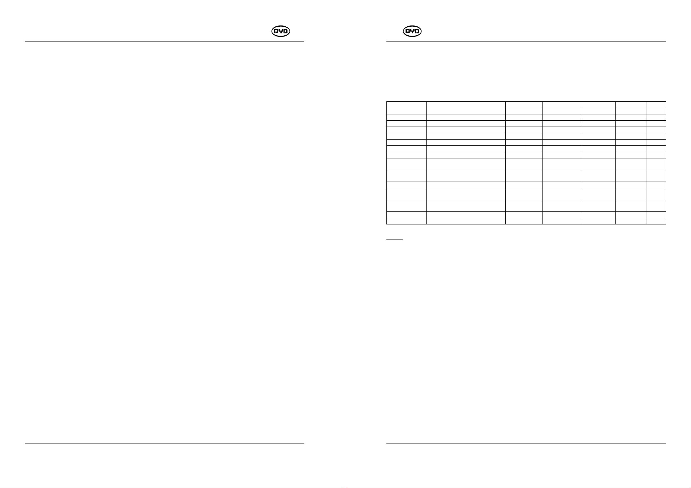
Category Items 6 weeks 3 6 12 Months
250 500 1000 2000 Hours
Chassis System Steering Axle Lubrication
Braking Fluid Replacement
Gear Oil Replacement 1st replacement Replacement
Mast Chains Adjustment Check
Lift Chains Lubrication Lubrication
Mast Cleaning Clean
Mast Lubrication Lubrication
Hydraulic System Hydraulic Oil Replacement of Main
Oil Tank
Replacement
Hydraulic Oil Replacement of Tilt
Mechanism
Replacement
Return Filter Element Replacement 1st replacement Replacement
High Pressure Filter Element
Replacement
1st replacement Replacement
Return Filter's Air Filter
Replacement
Replacement
Electric System Electric System Check
Others Torque on Critical Fasteners Check Check
Note
If the working environment is harsh, the maintenance interval should be reduced, and advice
from BYD after sales personnel should be sought.
Content Descriptions
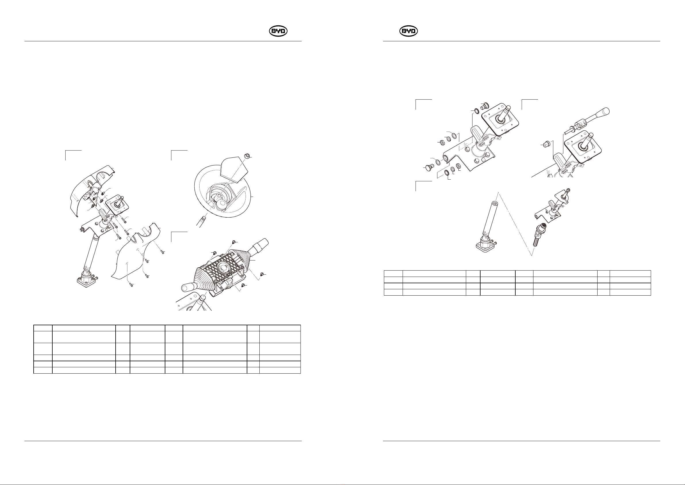
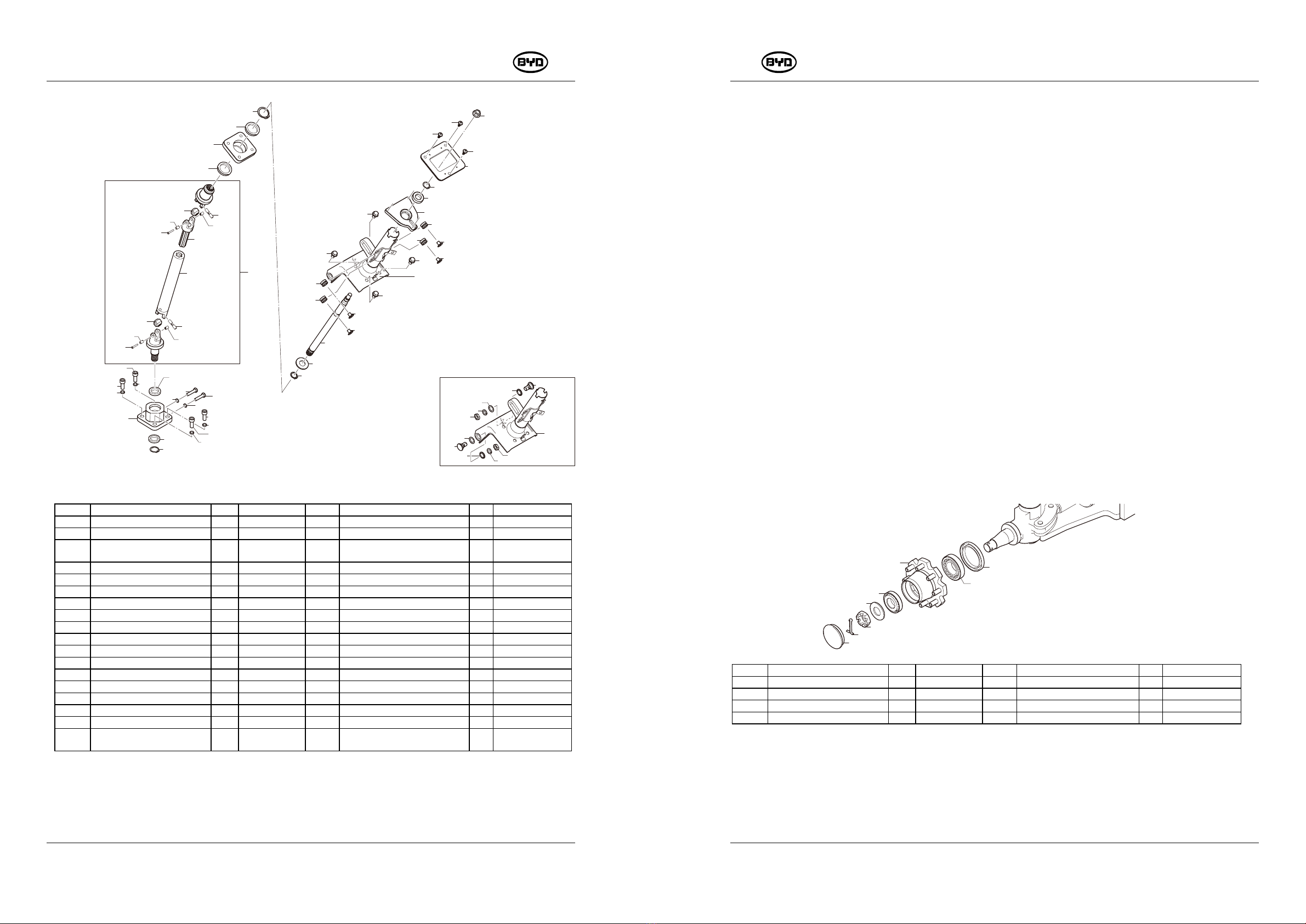
1.Chassis System
(1)Lubricate the drive axle.
(2)Replace the brake fluid.
(3)Replace the gear oil.
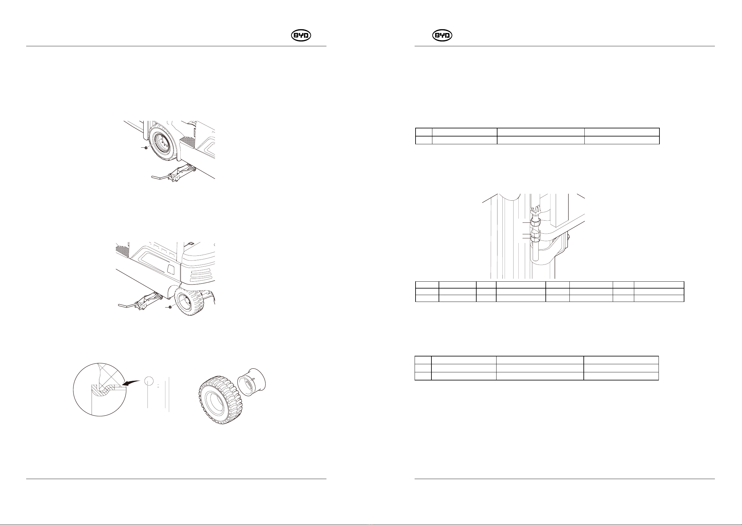
2.Mast
(1)Check the tightness of the chain and adjust if necessary.
(2)Lubricate the chains.
(3)Clean the mast.
3.Hydraulic System
(1)Replace hydraulic oil regularly.
(2)Replace return filter element
(3)Replace high pressure filter element
(4)Replace air filter
4.Electric System
(1)Check the electrical wiring of the forklift.
(2)Check fuse and relay.
(3)Check the main controller.
5.Others
Check torque on critical fasteners