BYD EPS14 User manual

SERVICE MANUAL
< SM-EPS142016002-EN >
EPS14


This manual is used for authorized personnel to sevice BYD forklifts

TABLE OF CONTENTS
SERVICE MANUAL 4
TABLE OF CONTENTS
MAINTENANCE INTERVAL
Daily Maintenance
Integral and Items 3
Content Description 3
Regular Maintenance
Integral and Items 5
Category, Amount And Type of Supplementary Material 5
Content Description 5
CHASSIS MAINTENANCE
Tiller Head and Tiller Arm
Description 7
Tiller Head Removal and Installation 7
Tiller Head Overhaul 8
Tiller Arm Removal and Installation 9
Tiller Arm Overhaul 10
Drive Axle and Wheel
Drive Wheel Replacement 11
Gear Oil Level Checking 11
Gear Oil Replacement 11
Drive Axle and Motor Assembly Removal and Installation 12
Drive Axle and Motor Separation 13
Drive Axle and Motor Installation 14
Balance Mechanism and Castor Wheels
Balance Inspection and Adjustment 15
Castor Wheel Replacement 15
Balance Mechanism Overhaul 16
Load Wheel
Load Wheel Replacement 17
MAST MAINTENANCE
Chain
2-Stage Standard Mast Lift Chain Adjustment 19
3-Stage Free Lift Mast (3 Cylinders) Chain Adjustment 19
2-Stage Standard Mast Chain Replacement 20
3-Stage Free Lift Mast (4 Cylinders) Chain Replacement 21
Lift Cylinder
Lift Cylinder Air-Exhausting 23
Cylinder Rod Lubrication 23
Lift Cylinder Shimming 23
Main Lift Cylinder Removal and Installation 24
Main Lift Cylinder Overhaul 25

EPS14
5SM-EPS142016002-EN
Free Lift Cylinder Removal and Installation 28
Free Lift Cylinder Overhaul 28
Mast and Carriage
Mast and Carriage Roller Description 31
General Carriage and Mast Clearance Adjustment 33
Mast Removal and Installation 34
Carriage Removal and Installation without Removing Mast 34
Carriage Removal and Installation after Removing Mast 35
Mast and Carriage Roller Replacement 35
HYDRAULIC MAINTENANCE
Hydraulic Oil
Hydraulic Oil Level Checking 38
Hydraulic Oil Replacement 38
Hydraulic Unit
Hydraulic Unit Removal and Installation 40
Hydraulic Unit Overhaul (R930053808 Type) 40
ELECTRIC MAINTENANCE
Electric Checking
Circuit Inspection 43
Fuses and Relays Inspection 43
Main Controller Inspection 43
Drive Motor
Drive Motor Electromagnetic Brake Replacement 44
Drive Motor Removal and Installation 44
Main Controller
Main Controller Removal and Installation 46
Main Controller Overhaul 46
Main Controller Program Downloading
Program Downloading Description 47
Program Downloading Procedure 48
Parameter Adjustment
Parameter Adjustment Description 49
Tiller Arm Angle Parameter Adjustment 49
OTHERS
Critical Fasteners Torque Checking 51
OTHER INFORMATION
Contact Information 54

MAINTENANCE INTERVAL
SERVICE MANUAL 2
MAINTENANCE INTERVAL
This chapter explains the maintenance interval.

EPS14
3SM-EPS142016002-EN
DAILY MAINTENANCE
Integral and Items
The period is accumulated in days or hours of operation whichever comes first. For example, if the forklifts works less than 8 hours
per day, conduct the following inspection and checks on a daily basis. If daily working hours exceed 8 hours, conduct the following
inspection and checks every 8 hours.
inspection checklist:
No. Item
1 Day 1 Week
8 Hours 40 Hours
1 Exterior Inspection
2 Wheel Clean and Tighten Clean and Tighten
3 Mast Inspection
4 Hydraulic Inspection
5 Display Inspection
6 Warning Equipments Inspection
7 Braking Inspection Inspection
8 Travel, Steering and Control Inspection
9 Electric Inspection
10 Clean Clean
11 Other Anomalies Inspection
Caution
These inspections should be conducted before operating the forklift.
Note
Before conducting the daily inspection, recheck for any fault and error found earlier.
Content Description
1. Exterior
(1) Check the truck body for damage and deformation.
(2) Check if there is any leakage.
(3) Check the condition of the nameplate and decals.
(4) Check if any parts loose or fall off.
Note
If any leakage occurs, confirm the location of the oil leakage and contact the after sale service.
2. Wheel
(1) Check on a daily basis if the wheel nuts are secured or loose. Fasten them if they are loose.
(2) Take out debris embedded in the tire.
(3) If the tires are unevenly worn, or the tires are found damaged, or the rims are bent, then replace the tires.
3. Mast
(1) Check the cylinders, oil pipes, and hoses for any oil leakage.
(2) Check the mast for deformation and damage. Check if the bolts are securely fastened.
4. Hydraulic
Check the hydraulic oil level in the oil tank.
5. Display
(1) Check if the battery voltage and status of charger displayed are correct.
(2) Check if any error or fault indicator appears.
6. Warning Equipments
(1) Press horn button to see if it works.

MAINTENANCE INTERVAL
SERVICE MANUAL 4
(2) Check if other warning equipments work properly.
7. Braking Performance
Brake the truck when driving it to checking it's performance.
8. Travel, Steering and Control Checking
(1) Check for the operation of the tiller and abnormal sounds by rotating the tiller forward or backward and turning the tiller
right or left.
(2) Check for the operation of buttons.
(3) Check if any fasteners loose or fall off.
9. Electric Checking
(1) Check if there any parts loose in the circuit and tighten them if necessary. Check if there are anything abnormal of
connectors (for example, burn marks).
(2) Check if the fuses of the controller are normal, replace them if necessary.
(3) Check if there are any burn marks on the connecting bars, replace them if necessary.
(4) Inspecting fuses and relays and replace them if necessary.
Warning
Disconnect the battery before checking the electric system.
10. Clean
Clean the truck.
11. Other Anomalies
Check if there are anything abnormal.

EPS14
5SM-EPS142016002-EN
REGULAR MAINTENANCE
Integral and Items
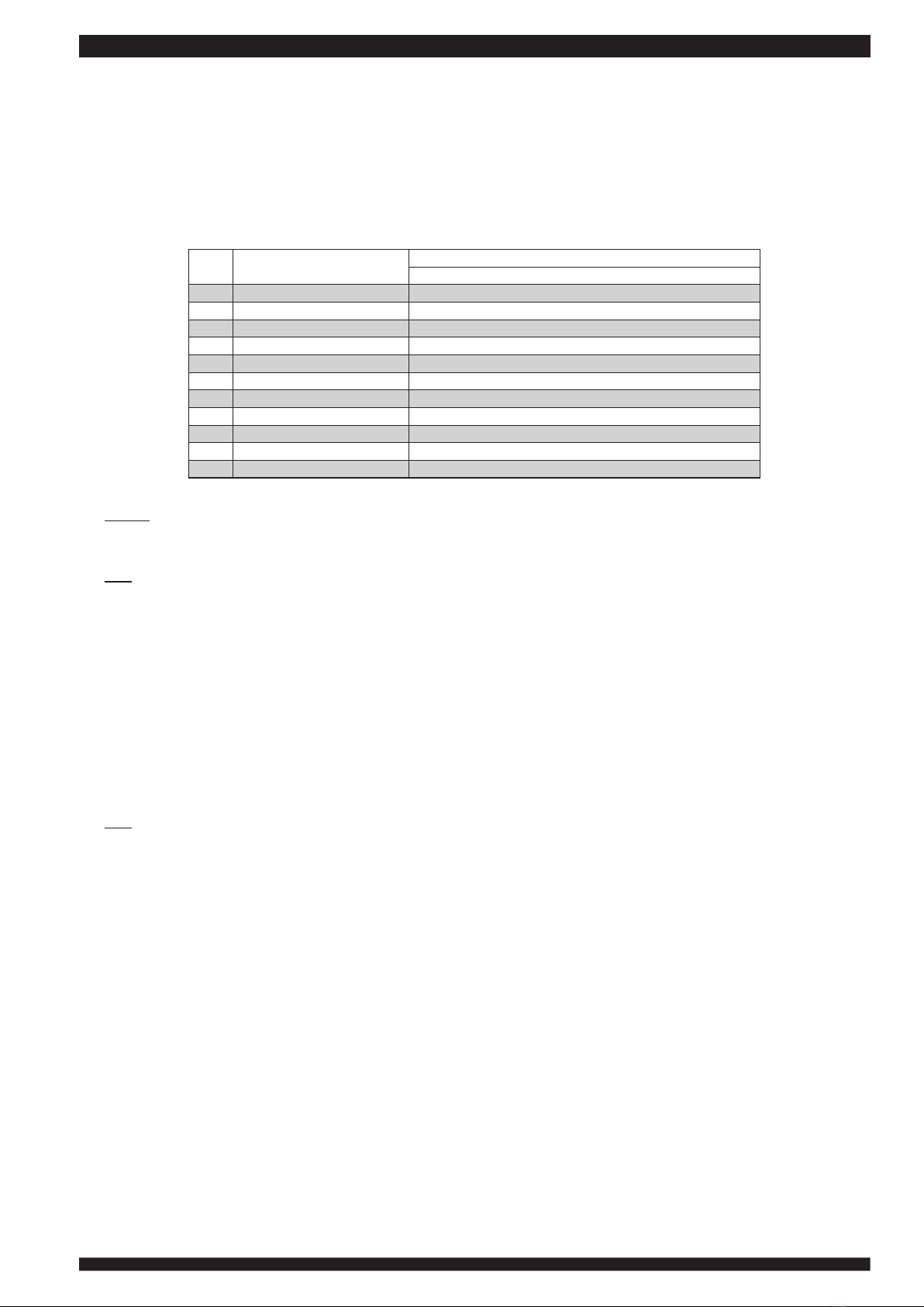
The period is accumulated in months or hours of operation whichever comes first. For example, if the truck works less than 250
hours in 6 weeks, conduct the following inspection and checks every 6 weeks, otherwise conduct the following inspection and checks
every 250 hours.
Category Item
6 (Weeks) 3 6 12 Months
250 500 1000 2000 Hours
Chassis Gear Oil Level Checking First Check Inspection
Mast
Lift Chain Adjustment Adjust
Lift Chain Lubrication Lubricate
Mast Cleaning Clean
Mast Clearance Adjustment Adjust
Hydraulic
Hydraulic Oil Replacement Replace
Oil Filter with Breather Filter Replace
Electric Electric Checking Inspection
Others Critical Fasteners Torque Checking Inspection
Note
If the working environment is harsh, the maintenance interval should be reduced, and advice from aftersales personnel should be
sought.
Category, Amount And Type of Supplementary Material
Item Category Amount Type
Gear Oil Level Checking Gear Oil 1.05 L SAE 80W-90
Lift Chain Lubrication Machine Oil As Needed 20# (Winter), 40# (Other Seasons)
Hydraulic Oil Replacement Hydraulic Oil 9 L ISO VG46 ( ≤46°C), ISO VG68 ( ≤68°C)
Note
The given quantities are maximum values and take the actual quantities as the standard.
Content Description
1. Chassis
Check the gear oil level, add it if necessary.
2. Mast
(1) Check the tension the lift chains, adjust them if necessary.
(2) Lubricate the lift chains.
(3) Clean the lift chains.
3. Hydraulic
(1) Replace the hydraulic oil periodically.
(2) Replace the oil filler with breather filler periodically.
4. Electric
(1) Check the circuit of the truck.
(2) Check fuses and relays.
Check the controller.
5. Others
Check the torque on the critical fastener.

CHASSIS MAINTENANCE
SERVICE MANUAL 6
CHASSIS MAINTENANCE
This chapter explains how to maintain the chassis of the truck.

EPS14
7SM-EPS142016002-EN
TILLER HEAD AND TILLER ARM
Description
The tiller head is fixed on the tiller arm, which is connected to the drive axle and motor assembly to steer the truck.
11
12
13
Code Name QTY Information Code Name QTY Information
11 Tiller Head 1 13 Drive Axle And Motor Assembly
12 Tiller Arm 1
Tiller Head Removal and Installation
1. Removal
(1) Remove the mounting screws to disassembly the tiller head.
(2) Remove the mounting screws of the tiller and the mounting bracket, and then remove the tiller head.

CHASSIS MAINTENANCE
SERVICE MANUAL 8
16
36
36 36
36
39
39 11
11
11
12
13
Code Name QTY Information Code Name QTY Information
11 Screw M6×10 3 16 Tiller Head Mounting Bracket 1
12 Tiller Head 1 36 Screw M6×30 4
13 Dataline 1 39 Screw M8×15 2
2. Installation
Follow the removal steps in reverse to install the tiller head.
Tiller Head Overhaul
Use the picture of the explosive view as the guide to overhaul the tiller head.
10
11
12
12
12
12
13
13
14
14
15
16
17
18
19
20
21
22
23
24
24
24
25
26
26
27
27
28 28
28 28
29
30
30
31
32
33
Code Name QTY Information Code Name QTY Information
10 Tiller 1 22 Upper Part 1
11 Horn Cover 1 23 Low Speed Switch Cover 1

EPS14
9SM-EPS142016002-EN
12 Spring For Horn And Low Speed Switch 4 24 Screw M6×10 3
13 Emergency Reverse Switch Spring 2 25 Lower Part 1
14 Bearing 2 26 Hinge Spring 2
15 Shaft 1 27 Sensor Rocker Lever 2
16 Washer 2 28 Magnet 4
17 Screw M3×16 2 29 Pcb 1
18 Butterfly Switch (Lh) 1 30 Magnet Holder 2
19 Butterfly Switch (Rh) 1 31 Rocker Lever (Lh) 1
20 Hinge Spring (Lh) 1 32 Rocker Lever (Rh) 1
21 Hinge Spring (Rh) 1 33 Emergency Reverse Switch Cover 1
Caution
Antistatic gloves are needed when the PCB is being removed or installed.
Tiller Arm Removal and Installation
1. Removal
(1) Remove the mounting screws of the tiller head and arm assembly, disconnect the dataline, and then remove the the tiller
head and arm assembly.
(2) Remove the tiller head.
< 1 ><2 >
16
36
36 36
36
39
39
33
37
11
11
11
10
12
13
Code Name QTY Information Code Name QTY Information
10 Tiller Head And Arm Assembly 1 33 Screw M8×45 6
11 Screw M6×10 3 36 Screw M6×30 4
12 Tiller Head 1 37 Washer M8 6
13 Dataline 1 39 Screw M8×15 2
16 Tiller Head Mounting Bracket 1
2. Installation
Follow the removal steps in reverse to install the tiller arm.

CHASSIS MAINTENANCE
SERVICE MANUAL 10
Tiller Arm Overhaul
Use the picture of the explosive view as the guide to overhaul the tiller arm.
10
31
11
11 11
11
12
12
12
12
12
12
12
12
13
14
15
16
17
18
19
21
22
23
24
25
26
20
36
36 36
36
33
37
33
37
39
39
Code Name QTY Information Code Name QTY Information
10 Tiller Head 1 21 Bushing 1
11 Screw M5×16 4 22 Washer 1
12 Screw M4×16 8 23 Screw M6×16 1
13 Cover 1 24 Rubber Cushion 1
14 Tiller Arm 1 25 Screw M6×16 1
15 Retainer Support 1 26 Retainer Shaft 1
16 Tiller Head Mounting Bracket 1 31 Angle Sensor 1
17 Connecting Block 1 33 Screw M8×45 6
18 Mounting Shaft 1 36 Screw M6×30 4
19 Gas Spring 1200N 1 37 Washer M8 6
20 Bushing 1 39 Screw M8×15 2

EPS14
11 SM-EPS142016002-EN
DRIVE AXLE AND WHEEL
Drive Wheel Replacement
Use the floor jack to raise the turk, and then place the hardwood block under it. Loosen the nuts to replace the wheel.
12 11
Code Name QTY Information
11 Hexagon Nut 5 90 N-m
12 Spherical Spring Washer 5
Gear Oil Level Checking
(1) Clean the surrounding areas around the oil filler plug, and then unscrew it with the seal.
(2) Check the oil level. The correct oil level and the correct oil quantity is achieved when the oil level is at the lower edge of the
oil filler plug. Add gear oil if necessary.
(3) After checking, screw in the oil filler plug with the sealing ring.
11
12
Code Name QTY Information
11 Oil Filler Plug 1 30 N-m
12 Seal 1
Caution
(2) When filling the oil, care about the condition around to prevent dust and water entering the gear box.
(3) The correct oil level and the correct oil quantity is achieved when the oil level is at the lower edge of the oil filler plug
Gear Oil Replacement
(1) Clean the surrounding areas around the oil filler plug and the oil drain plug, and place a suitable vessel under the oil.
(2) Unscrew the oil filler plug and the oil drain plug with sealing rings.
(3) After draining, screw in the oil drain plug with the new sealing ring.
(4) Add gear oil until the oil level is at the lower edge of the oil filler plug. Screw in the oil filler plug with the sealing ring.

CHASSIS MAINTENANCE
SERVICE MANUAL 12
11
12
13
12
Code Name QTY Information Code Name QTY Information
11 Oil Filler Plug 1 30 N-m 13 Oil Drain Plug 1 30 N-m
12 Seal 2
Caution
(2) Oil drain time of approximate 5 minutes must not be exceeded.
(3) When filling the oil, care about the condition around to prevent dust and water entering the gear box.
(4) When disposing the waste oil, keep children away and do not pour it into the sewer or onto the ground.
(5) The correct oil level and the correct oil quantity is achieved when the oil level is at the lower edge of the oil filler plug
Drive Axle and Motor Assembly Removal and Installation
1. Removal
(1) Before removal, remove the cover.
(2) Remove the tiller head and arm assembly.
(3) Disconnect cables(high and low voltage cables).
(4) Remove the fasteners of the drive axle and motor assembly, hoist the truck frame, and then separate them.
(5) Put the drive axle and motor assembly on the flat floor or sturdy pallets.

EPS14
13 SM-EPS142016002-EN
< 1 ><2 >
< 3 > < 4 >
33
37
10
11
11
11
11
11
11
Code Name QTY Information Code Name QTY Information
10 Tiller Head And Arm Assembly 1 33 Screw M8×45 6
11 Hexagon Flange Bolt M10×45 6 37 Washer M8 6
2. Installation
Slowly set the drive axle and motor assembly down on the flat floor or sturdy pallets.
Drive Axle and Motor Separation
Remove the mounting bolts to remove the motor.

CHASSIS MAINTENANCE
SERVICE MANUAL 14
19
12
13
12
13
14
15
15
15
13
13
13
11
10
18
Code Name QTY Information Code Name QTY Information
10 Drive Motor 1 14 Mounting Block 1
11 Nut M12 1 15 Hexagon Screw M8×50 3
12 Screw M8×25 2 18 Pinion 1
13 Washer M8 5
Drive Axle and Motor Installation
Follow the separation steps in reverse to install the motor on the drive axle.

EPS14
15 SM-EPS142016002-EN
BALANCE MECHANISM AND CASTOR WHEELS
Balance Inspection and Adjustment
If the abnormal shaking occurs, the truck balance is needed to adjusted. Remove the back cover, and then use the retainer to adjust
the balance. Before adjustment, place the truck on the sturdy and level ground, and then loosen the mounting bolt of the castor wheel
assembly.
(1) When the front right side or the rear left side of the truck shakes, turn the retainer upward.
(2) When the front left side or the rear right side of the truck shakes, turn the retainer downward.
< 1 >
< 2 >
19
22
21
11
19
22
21
11
Code Name QTY Information Code Name QTY Information
11 Retainer 1 21 Bolt M12×45 1
19 Washer M12 1 22 Spring Washer 1
Castor Wheel Replacement
(1) Use the floor jack to raise the truck, and then place the hardwood block under it. Loosen the bolt to take out the wheel
assembly.
(2) Loosen the nut and bolt to replace the wheel.
15
16 17
18
20
20
23
23
23
19
22
21
Code Name QTY Information Code Name QTY Information
15 Bolt M16×160 1 20 Castor Wheel 2
16 Nut M16 1 110 N-m 21 Bolt M12×45 1 90 N-m

CHASSIS MAINTENANCE
SERVICE MANUAL 16
17 Bushing 1 22 Spring Washer 1
18 Spring Washer M16 1 23 Wahser 3
19 Washer M12 1
Balance Mechanism Overhaul
Use the picture of the explosive view as the guide to overhaul the balance mechanism.
< A >
11
12
13
13
14
15
16 17
18
19
22
21
20
20
23
23
23
24
< A >
Code Name QTY Information Code Name QTY Information
11 Retainer 1 18 Spring Washer M16 1
12 Mounting Tube 1 19 Washer M12 1
13 Bearing 2 20 Castor Wheel 2
14 Circlip 1 21 Hexagon Bolt M12×45 1
15 Bolt M16×160 1 22 Spring Washer 1
16 Nut M16 1 23 Wahser 3
17 Bushing 1 24 Support 1
Table of contents
Other BYD Forklift manuals
Popular Forklift manuals by other brands

Hyster
Hyster C219 Service & repair manual

VIA Technologies
VIA Technologies Mobile360 FSS installation guide

GÜDE
GÜDE GHW 2500 PU K Translation of the original instructions

Komatsu
Komatsu CX20 Series Service manual

Cascade
Cascade F Series Installation instruction

Hyster
Hyster W30-40ZA Service & repair manual