manuals.online logo
Brands
  1. Home
  2. •
  3. Brands
  4. •
  5. C.A. Technologies
  6. •
  7. Paint Sprayer
  8. •
  9. C.A. Technologies AutoCAT 100C User manual

C.A. Technologies AutoCAT 100C User manual

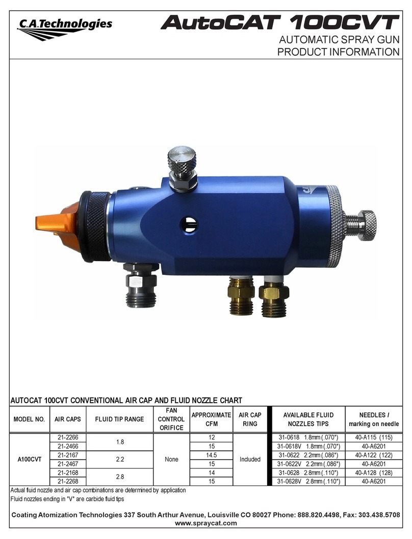
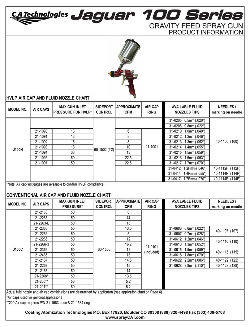
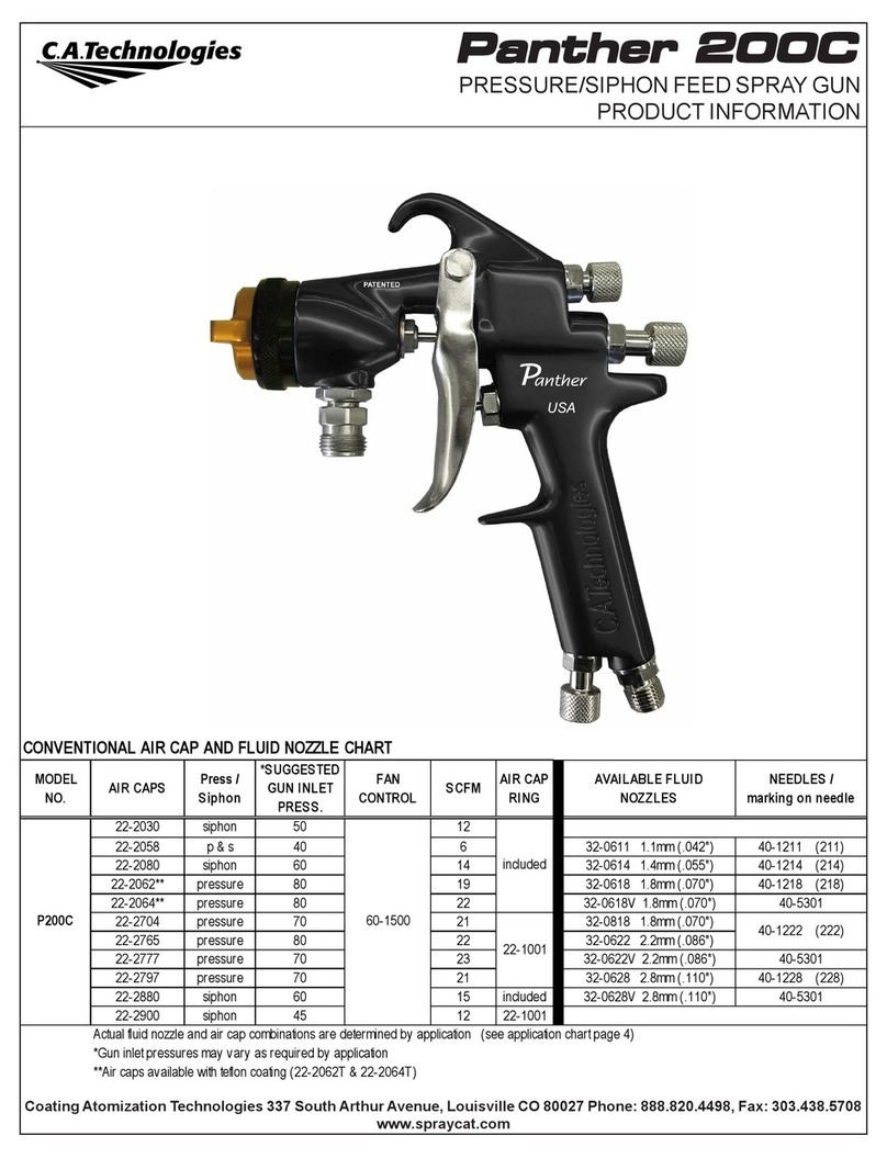
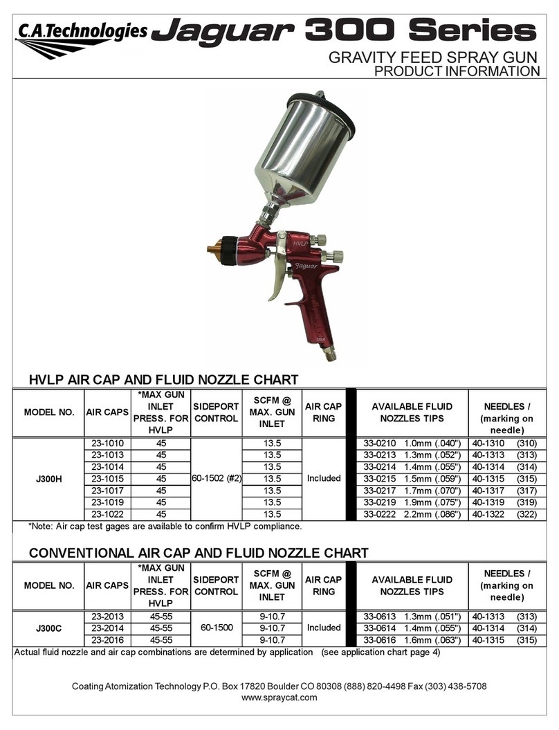
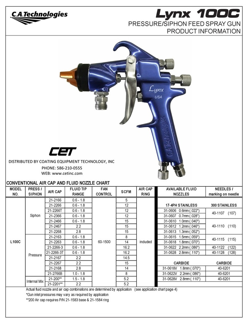
CONVENTIONAL AIR CAP AND FLUID NOZZLE CHART
MODEL
NO.
PRESS /
SIPHON AIR CAP FLUID TIP
RANGE
FAN
CONTROL
ORIFICE
SCFM AIR CAP
RING
AVAI LABL E F LUI D
NOZZLES
NEEDLES /
marking on needle
21-2166 0.6 - 1.8 5
21-2266 0.6 - 1.8 12 17-4PH STAINLESS 300 STAINLESS
21-2266T 0.6 - 1.8 12 31-0606 0.6mm (.022")
21-2366 0.6 - 1.8 12 31-0607 0.7mm (.028")
21-2466 0.6 - 1.8 15 31-0610 1.0mm (.040")
21-2467 2.2 15 31-0612 1.2mm (.046")
21-2268 2.8 15 31-0613 1.3mm (.052")
21-2163 0.6 - 1.8 8 31-0615 1.5mm (.059")
21-2263 0.6 - 1.8 14 31-0618 1.8mm (.070")
21-2266-3 0.6 - 1.8 16.2 31-0622 2.2mm (.086") 40-A122 (122)
21-2266-3T 0.6 - 1.8 16.2 31-0628 2.8mm (.110") 40-A128 (128)
21-2167 2.2 14.5
21-2267 2.2 15 CARBIDE CARBIDE
21-2168 2.8 14 31-0618V 1.8mm (.070") 40-A6201
21-2766B 1.0 - 1.8 8 31-0622V 2.2mm (.086") 40-A6201
21-200** 1.5 - 1.8 5.2 31-0628V 2.8mm (.110") 40-A6201
21-2201** 2.2 5.2
Actual fluid nozzle and air cap combinations are determined by application (see application chart page 4)
*Gun inlet pressures may vary as required by application
**200 Air cap requires P/N 21-1583 base & 21-1584 ring
40-A107 (107)
40-A110 (110)
40-A115 (115)
A100C None Included
Siphon
Pressure
Internal Mix
AUTOMATIC SPRAY GUN
PRODUCT INFORMATION
Coating Atomization Technologies 337 South Arthur Avenue, Louisville CO 80027 Phone: 888.820.4498, Fax: 303.438.5708
www.spraycat.com
AA
AA
Autut
utut
utoCoC
oCoC
oCAA
AA
AT 1T 1
T 1T 1
T 100C00C
00C00C
00C
Operation and Maintenance Instructions for
A100CA100C
A100CA100C
A100C
Spray Guns
Gun Mounting
A 1/2” dia. x 5” lg. rod is provided for mounting. The gun can be mounted from the left or right side or from the bottom.
Thread the mounting rod (9) into one of the three holes that best suit the mounting location for the application. Tighten
the locknut (10) to secure the gun in the position desired. Do not plug the remaining holes as they are used as drain
holes in the event of a needle seal leak.
Operation: Connections and Adjustments
The automatic gun requires two separate regulated air supply lines.
1. Connect one air line to the fitting marked “CYL”, this actuates the gun on and off and is usually connected through an
air solenoid.
2. Connect the second air line to the fitting marked “ATM”, this provides atomizing and fan air.
3. Connect a pressurized fluid supply to the gun fluid inlet.
4. Fluid flow can be controlled using the fluid control knob, this restricts flow by limiting needle travel. It is best to control
fluid flow by proper selection of fluid orifice size and use the fluid control knob to “fine tune flow rate”.
5. Fan width can be adjusted using the fan control knob. Turning the knob clockwise narrows the fan.
Maintenance: Needle Seal Replacement
IMPORTANT! Routine cleaning and maintenance is essential to insure proper gun operation.
Before beginning needle seal replacement, it is recommended kit no. 10-107 be on hand.
Several states prohibit spraying solvent into the atmosphere and require the use of covered gun cleaner.
1. Remove fluid control knob (36), needle return spring (34), and needle assembly (33).
2. Remove end cap (32) and piston return spring (31).
3. Piston (29) can be removed with pliers by carefully gripping the hub on the rear of the piston.
4. Remove the air control spool (22) using an 11/16” socket to unscrew it from the body.
5. The needle seal can be removed using a 7/16” socket with a short extension. Install a new needle seal and torque to
approx. 2 ft.-lbs.
6. It is recommended that the o-rings on the air control spool (22) and piston (29) be replaced and lubricated before
reassembling the gun.
NOTE: Gun head disassembly is not recommended for normal cleaning and maintenance.
Gun head disassembly and reassembly instructions:
Have repair kit # 10-107 available before gun disassembly.
Gun head disassembly
To remove the nozzle carrier (6) and air cap adapter (7):
1. Remove the air cap (1), fluid nozzle tip (3), fluid nozzle body (4), and needle (33).
2. Remove the needle seal cartridge (18) as described above.
3. Loosen the locknut (26) using 11/16” wrench and remove fluid inlet (27) using a 5/8” open-end wrench.
4. The nozzle carrier (6) and air cap adapter (7) will now slide forward from the gun body (11).
Gun head reassembly
1. Install a new o-ring (8) on the air cap adapter (7).
2. Install gasket (5) into the air cap adapter (7).
3. Install the thread locknut (26) onto the fluid inlet (27) as far as possible.
4. Install a new fluid inlet seal (25) into the recess area on the nozzle carrier (6) inlet port.
5. Slide the nozzle carrier (6) into air cap adapter (7) and insert into the gun body (11) as far as possible. Be sure the
nozzle carrier (6) extends into the hole at the back of the gun head. Install the needle seal (18) but do not tighten.
6. Rotate the nozzle carrier (6) until the fluid inlet port in the nozzle carrier (6) is aligned with the threaded hole in the
body. While in this position, insert the fluid inlet (27) and tighten firmly.
7. Tighten the needle seal (18) to approx. 12 ft.-lb. torque.
8. Tighten the fluid inlet (27) to approx. 25 ft.-lb. torque.
9. Tighten the locknut (26) to approx. 33 ft.-lb. torque.
*
*
*
*
*
*
*
*
*
*
*
*
ITEM NO. PART NO. DESCRIPT ION ITEM NO. PART NO. DESCRIPT ION
1 See Air Cap Chart Air Cap** 21 98-7006 O-Ring (Viton) 2 Required*
3 See Air Cap Chart Fluid Tip** 22 60-603 Air Control Spool
4 31-2201 Fluid Nozzle Body 23 98-7014 O-Ring (Viton) 2 Required*
5 61-1005 Seal* 24 98-7027 O-Ring (Viton) 2 Required*
6 60-L11C Nozzle Body Carrier 25 60-124 Seal*
7 60-12C Air Cap Adapter 26 60-128 Locknut
8 60-131 O-Ring (Teflon)* 27 60-126 Fluid Inlet
9 60-614 Mounting Rod 28 98-8010 O-Ring (Teflon)*
10 98-0115 Locknut (3/8-16) 29 60-602 Piston
11 60-622 AutoCAT Gun Body Conventional 30 98-7217 O-Ring (Viton)*
12 60-136 Plug 31 66-246 Piston Return Spring
13 98-8108 O-Ring (Tef lon)* 32 60-601 End Cap
14 98-0108 Circlip 33 See Air Cap Chart Needle Assembly
15 60-605 Fan Control Housing 34 60-613 Needle Return Spring
16 60-606 Fan Control Stem 35 60-612 Locknut - Fluid Control Knob
18 60-1400 Needle Seal Assembly* 36 60-608 Fluid Control Knob
19 60-604 Seal Cap 37 53-551 (Not Show n)*** Cylinder Air Fitting 1/8 NPT x 1/4 NPS
20 98-8006 O-Ring (Teflon)* 38 53-552 (Not Show n)*** Atomz. Air Fitting 1/4 NPT x 1/4 NPT
*Indicates part included in repair kit # 10-107
**See air cap selection chart on page 1
***Air inlet fittings are available in 90 degree elbow . 90 degree elbow tubing "push on" style fittings
P/N 53-520 1/8 NPT x 1/4" OD Tube
P/N 53-521 1/4 NPT x 3/8" OD Tube
A100C CONVENTIONAL AUTOMATIC SPRAY GUN
MATERIAL TYPE FLUID ORIFICE x
AI R C AP
MAXIMUM
PATTERN WIDTH PRESS. / SIPHON
Very Thin
less than 16 sec. Zahn #2
inks , dyes,
solvents, stains
Thin
16 to 20 sec. Zahn #2
lacquers, enamels,
primers, sealers
Medium
21 to 30 sec. Zahn #2
automotive base coat
enamels, primers
epoxies, urethanes
automotive clear coat
Heavy
over 30 sec. Zahn #2
heavy body primers
high solid enamels
high solid automotive coatings
adhesives
FLUID NOZZLE / AIR CAP SELECTION CHARTS
AUTOCAT Series 100C - Pressure / Siphon Feed Guns
0.6, 0.7 mm x 2163
0.6, 0.7 mm x 2166
0.6, 0.7 mm x 2266
8
9
12
P
S
S
1.5, 1.8mm x 2466
2.2 mm x 2167
2.2 mm x 2267
2.8 mm x 2168
13
12
15
12
S
P
P
P
0.6, 0.7, 1.0 mm x 2163
0.6, 0.7, 1.0 mm x 2366
0.6, 0.7, 1.0 mm x 2466
8
14
13
P
S
S
1.2, 1.3, 1.5, 1.8 mm x 2263
1.2, 1.3, 1.5, 1.8 mm x 2266
1.2, 1.3, 1.5, 1.8 mm x 2266-3
1.2, 1.3, 1.5, 1.8 mm x 2466
14
10
15
13
P
S
S
S
Revised 3/18/14

This manual suits for next models

1

Other C.A. Technologies Paint Sprayer manuals

C.A. Technologies Lynx 300H User manual

C.A. Technologies

C.A. Technologies Lynx 300H User manual

C.A. Technologies Jaguar 100 Series User manual

C.A. Technologies

C.A. Technologies Jaguar 100 Series User manual

C.A. Technologies Lynx L100C User manual

C.A. Technologies

C.A. Technologies Lynx L100C User manual

C.A. Technologies CPR-FE User manual

C.A. Technologies

C.A. Technologies CPR-FE User manual

C.A. Technologies Panther 100G 1590 User manual

C.A. Technologies

C.A. Technologies Panther 100G 1590 User manual

C.A. Technologies Lynx 100C 1590 User manual

C.A. Technologies

C.A. Technologies Lynx 100C 1590 User manual

C.A. Technologies Techline JR User manual

C.A. Technologies

C.A. Technologies Techline JR User manual

C.A. Technologies CAT-Xpress Troubleshooting guide

C.A. Technologies

C.A. Technologies CAT-Xpress Troubleshooting guide

C.A. Technologies Jaguar SLP User manual

C.A. Technologies

C.A. Technologies Jaguar SLP User manual

C.A. Technologies Panther 200C User manual

C.A. Technologies

C.A. Technologies Panther 200C User manual

C.A. Technologies FE-Line Fine Finish User manual

C.A. Technologies

C.A. Technologies FE-Line Fine Finish User manual

C.A. Technologies CPR User manual

C.A. Technologies

C.A. Technologies CPR User manual

C.A. Technologies Jaguar 300H User manual

C.A. Technologies

C.A. Technologies Jaguar 300H User manual

C.A. Technologies Tomcat Series User manual

C.A. Technologies

C.A. Technologies Tomcat Series User manual

C.A. Technologies Panther 100G User manual

C.A. Technologies

C.A. Technologies Panther 100G User manual

C.A. Technologies Lynx 300C Troubleshooting guide

C.A. Technologies

C.A. Technologies Lynx 300C Troubleshooting guide

C.A. Technologies Lynx 100C User manual

C.A. Technologies

C.A. Technologies Lynx 100C User manual

C.A. Technologies AutoCAT 100CVT User manual

C.A. Technologies

C.A. Technologies AutoCAT 100CVT User manual

C.A. Technologies Lynx 100H User manual

C.A. Technologies

C.A. Technologies Lynx 100H User manual

C.A. Technologies Panther 200Z User manual

C.A. Technologies

C.A. Technologies Panther 200Z User manual

C.A. Technologies CAT SLP Series User manual

C.A. Technologies

C.A. Technologies CAT SLP Series User manual

C.A. Technologies Tomahawk TG User manual

C.A. Technologies

C.A. Technologies Tomahawk TG User manual

C.A. Technologies LYNX L100CM Manual

C.A. Technologies

C.A. Technologies LYNX L100CM Manual

C.A. Technologies CPR User manual

C.A. Technologies

C.A. Technologies CPR User manual

Popular Paint Sprayer manuals by other brands

GUSMER GAP operating manual

GUSMER

GUSMER GAP operating manual

LavorPro FOAM BOX User instructions

LavorPro

LavorPro FOAM BOX User instructions

WAGNER GM 5000EA operating manual

WAGNER

WAGNER GM 5000EA operating manual

TRAPP 5 liters instruction manual

TRAPP

TRAPP 5 liters instruction manual

Graco DutyMax DH230 Operation, parts

Graco

Graco DutyMax DH230 Operation, parts

Nordson Tribomatic 2 Customer product manual

Nordson

Nordson Tribomatic 2 Customer product manual

SPI LPG Synergy Series Operation manual

SPI

SPI LPG Synergy Series Operation manual

Air & Allied Sales UGC2005 operating instructions

Air & Allied Sales

Air & Allied Sales UGC2005 operating instructions

Storm Machinery 5008 Operating instructions & service manual

Storm Machinery

Storm Machinery 5008 Operating instructions & service manual

Graco Reactor 2 E-30 repair parts

Graco

Graco Reactor 2 E-30 repair parts

WALTHER PILOT wa200 operating instructions

WALTHER PILOT

WALTHER PILOT wa200 operating instructions

SATA top air operating instructions

SATA

SATA top air operating instructions

Binks 230 Operation manual

Binks

Binks 230 Operation manual

Graco Ultimate NOVA 395 PC Operation, parts

Graco

Graco Ultimate NOVA 395 PC Operation, parts

Solo 460 Li Original instructions

Solo

Solo 460 Li Original instructions

WALTHER PILOT PILOT WA 905 operating instructions

WALTHER PILOT

WALTHER PILOT PILOT WA 905 operating instructions

WAGNER W950 Flexio manual

WAGNER

WAGNER W950 Flexio manual

Smith Performance Sprayers S103EX use and care manual

Smith Performance Sprayers

Smith Performance Sprayers S103EX use and care manual

manuals.online logo
manuals.online logoBrands
  • About & Mission
  • Contact us
  • Privacy Policy
  • Terms and Conditions

Copyright 2025 Manuals.Online. All Rights Reserved.