manuals.online logo
Brands
  1. Home
  2. •
  3. Brands
  4. •
  5. C.P. Electronics
  6. •
  7. Security Sensor
  8. •
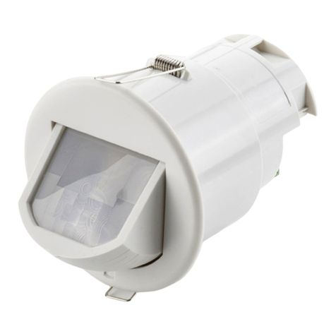
  9. C.P. Electronics SPIR-PRM User manual

C.P. Electronics SPIR-PRM User manual

MRT-PRM
Push button activation with optional external trigger
Compatible with all BS4662
dimensions back boxes.
Remove top and bottom lugs if
fitted.
Use the extender if there is less than
25mm free space.
REMEMBER—put the wires through
the extender before connecting.
< 25mm
Do not
overtighten
The SPIR-PRM presence detector switches are designed to provide
automatic control of lighting, heating or ventilation loads. They detect
movement using a PIR sensor and turn the load on. When an area is no
longer occupied the load will switch off after an adjustable time out pe-
riod.
An internal light sensor provides additional energy saving in lighting
applications. When an area is occupied lighting is only switched on when
the level of natural light is below a preset level.
When the unit is first powered up the PIR sensor will always detect im-
mediately regardless of whether the room is occupied. A selectable
power up delay allows the installer to choose whether the load comes on
immediately when the unit is powered up or is kept off for a small time
(about 40 seconds) to allow the sensor to settle.
Wire the SPIR-PRM as in the diagram.
To switch from more than one position simply wire two or more
units in parallel to achieve two way and intermediate switching.
The detector should be sited so that the occupants of the room
fall inside the detection pattern shown below, at a recommended
height of 1.2m to 1.5m for wall sensors. Note that the higher the
sensor is installed the shorter the detection range will be.
 Avoid direct sunlight entering the sensor.
 Do not site within 1m of forced air heating
or ventilation.
 Do not site within 1m of any lighting.
 Do not fix to a vibrating surface.
Installation & Wiring
Wall Mounted PIR Presence Detector
SPIR-PRM
Product Guide
Overview
LOAD
16 Amp resistive load
10 Amp incandescent lighting
6 Amp fluorescent lighting
3 Amp compact fluorescent lighting
3 Amp low energy lighting
3 Amp low voltage lighting (switch primary of transformer)
3 Amp fans and ventilation equipment
Switch SON lighting loads via a contactor
Quartz halogen heaters: 2600W max, recommended timing 30 minutes, for lower timing switch
via contactor
SUPPLY VOLTAGE 220-240 Volts AC 50 Hz
TIME OUT PERIOD Adjustable 10 seconds to 60 minutes in two ranges
LIGHT LEVEL Optional adjustment by thumbwheel light to dark.
TERMINAL CAPACITY 2.5mm2
MATERIAL Flame retardant ABS
TYPE Class 2
TEMPERATURE -10°C to 35°C
CONFORMITY EN60669-2-1
EN55015
LOAD DOES NOT COME ON
Check to see if the live supply to the circuit is
good. Strap across the L and LIVE OUT termi-
nal to turn the load on.
If the supply and wiring are good, check the
LUX level setting. Increase the LUX level set-
ting to allow the controller to turn on at higher
ambient natural light level.
LIGHTS DO NOT GO OFF
Ensure that the area is left unoccupied for a
greater time period than the time out period set
using the switch.
Make sure that the sensor is not adjacent to
circulating air, heaters or lamps.
Part Numbers
Fault Finding Specification
SPIR-PRM Wall mounted PIR presence detector
Setup
Switch settings
Time setting
Lux setting
1. Set the LUX level thumbwheel fully clockwise.
2. Set the time to minimum (fully anticlockwise) and set both switches to ON (0-1/2 hour range, no power up delay) according to the diagram.
3. Apply power—the load should come on immediately.
4. Vacate the room or remain very still and wait for the load to switch off (should take no more than 2 minutes).
5. Check that the load switches on when movement is detected.
6. To set the final LUX level wait until the level of natural daylight is just enough that lighting is required. Starting with the LUX thumbwheel fully
anti-clockwise. Very slowly turn the thumbwheel clockwise until the lights come on. Note that when the LUX thumbwheel is fully clockwise then
the lights will always come on with occupancy.
7. Select the time out range using switch 1 according to the diagram. Set the time out period using the thumbwheel, fully clockwise is the maxi-
mum (either 1/2 hour or 1 hour depending on the range).
8. If required, select the power up delay using switch 2 (to prevent the load coming on immediately on power up).
Due to our policy of continual product improvement CP Electronics reserves the right to alter the specification of this product without prior notice.
FM 45789 EMS 534520
C.P. Electronics Ltd
Brent Crescent
London
NW10 7XR
United Kingdom
Tel: + 44 (0) 333 900 0671
Fax: + 44 (0) 333 900 0674
www.green-iswitches.co.uk
enquiry@green-iswitches.co.uk
Ref: #WD283 Issue 3
IMPORTANT NOTICE!
This device should be installed by a qualified electrician in
accordance with the latest edition of the IEE Wiring
Regulations and any applicable Building Regulations.

Other C.P. Electronics Security Sensor manuals
C.P. Electronics MWS3A-AT-PRM User manual

C.P. Electronics

C.P. Electronics MWS3A-AT-PRM User manual

C.P. Electronics EBMHS-AD-SA-C User manual
C.P. Electronics

C.P. Electronics EBMHS-AD-SA-C User manual

C.P. Electronics VITMR-MWS6-PRM User manual

C.P. Electronics

C.P. Electronics VITMR-MWS6-PRM User manual

C.P. Electronics EBDHS-DNET1 User manual

C.P. Electronics

C.P. Electronics EBDHS-DNET1 User manual

C.P. Electronics MWS3A-PRM User manual

C.P. Electronics

C.P. Electronics MWS3A-PRM User manual

C.P. Electronics MWS3A-DD-LV User manual

C.P. Electronics

C.P. Electronics MWS3A-DD-LV User manual

C.P. Electronics MWS6-PRM-LV User manual

C.P. Electronics

C.P. Electronics MWS6-PRM-LV User manual

C.P. Electronics EBDSPIR-DD User manual

C.P. Electronics

C.P. Electronics EBDSPIR-DD User manual

C.P. Electronics EBDSPIR-KNX User manual
C.P. Electronics

C.P. Electronics EBDSPIR-KNX User manual

C.P. Electronics EBMINT-PRM User manual

C.P. Electronics

C.P. Electronics EBMINT-PRM User manual

C.P. Electronics SPIR-F/C/IP User manual

C.P. Electronics

C.P. Electronics SPIR-F/C/IP User manual

C.P. Electronics MWS3A-PRM-VFC User manual

C.P. Electronics

C.P. Electronics MWS3A-PRM-VFC User manual

C.P. Electronics MWS6-PRM-VFC-LV User manual

C.P. Electronics

C.P. Electronics MWS6-PRM-VFC-LV User manual

C.P. Electronics MWS6-PRM-VFC User manual

C.P. Electronics

C.P. Electronics MWS6-PRM-VFC User manual

C.P. Electronics EBDHS-DNET1-LT30 User manual

C.P. Electronics

C.P. Electronics EBDHS-DNET1-LT30 User manual

C.P. Electronics EBDSPIR-PRM-L3 User manual

C.P. Electronics

C.P. Electronics EBDSPIR-PRM-L3 User manual

C.P. Electronics MWS3A-PRM-LV User manual

C.P. Electronics

C.P. Electronics MWS3A-PRM-LV User manual

C.P. Electronics MWS1A-PRM User manual

C.P. Electronics

C.P. Electronics MWS1A-PRM User manual

C.P. Electronics MWS3A-DD User manual

C.P. Electronics

C.P. Electronics MWS3A-DD User manual

C.P. Electronics MWS1A-IP-PRM-VFC User manual

C.P. Electronics

C.P. Electronics MWS1A-IP-PRM-VFC User manual

C.P. Electronics EBDSPIR-AD User manual

C.P. Electronics

C.P. Electronics EBDSPIR-AD User manual

C.P. Electronics Green-i GESM User manual

C.P. Electronics

C.P. Electronics Green-i GESM User manual

C.P. Electronics GENB-IR User manual

C.P. Electronics

C.P. Electronics GENB-IR User manual

C.P. Electronics MWS1A-C-IP-PRM-LV User manual
C.P. Electronics

C.P. Electronics MWS1A-C-IP-PRM-LV User manual

Popular Security Sensor manuals by other brands

IFM Electronic Efector 500 PN20 Series operating instructions

IFM Electronic

IFM Electronic Efector 500 PN20 Series operating instructions

Panasonic HL-G1 Series user manual

Panasonic

Panasonic HL-G1 Series user manual

Guardall V12AM installation guide

Guardall

Guardall V12AM installation guide

THORLABS PDAPC1 user guide

THORLABS

THORLABS PDAPC1 user guide

Resolution Products RE110P+ instructions

Resolution Products

Resolution Products RE110P+ instructions

IFM UGR502 operating instructions

IFM

IFM UGR502 operating instructions

Rae ToxiRAE 3 quick start guide

Rae

Rae ToxiRAE 3 quick start guide

ARTANI True user manual

ARTANI

ARTANI True user manual

PCB Piezotronics W200B03/002C05 Installation and operating manual

PCB Piezotronics

PCB Piezotronics W200B03/002C05 Installation and operating manual

UTC Fire and Security interlogix ShatterPro 3 installation instructions
UTC Fire and Security

UTC Fire and Security interlogix ShatterPro 3 installation instructions

Comunello Automation DART SLIM SYNC Installation and user manual

Comunello Automation

Comunello Automation DART SLIM SYNC Installation and user manual

Satel DMP-100 installation manual

Satel

Satel DMP-100 installation manual

Alula RE200-5T quick start guide

Alula

Alula RE200-5T quick start guide

Robus RU360-01 manual

Robus

Robus RU360-01 manual

AirTest IAQEye TR8910 user manual

AirTest

AirTest IAQEye TR8910 user manual

Lexing LX-MV-360S10-A instructions

Lexing

Lexing LX-MV-360S10-A instructions

Linear DF-16/EC installation instructions
Linear

Linear DF-16/EC installation instructions
SICK i200 Lock operating instructions

SICK

SICK i200 Lock operating instructions

manuals.online logo
manuals.online logoBrands
  • About & Mission
  • Contact us
  • Privacy Policy
  • Terms and Conditions

Copyright 2025 Manuals.Online. All Rights Reserved.