CAB HD.80 User manual

L854200072
05/2019 rev. 0
HYDRO
HD.80
IT
EN
DE
FR

3
Dati tecnici Technical data
HD.80 230V HD.80 115V
Alimentazione Power supply 230Vac (50/60Hz) 115Vac (50/60Hz)
Motore Motor 1400g/min 1400g/min
Corrente assorbita Absorbed current 1,3 A 2,6 A
Spinta Thrust
10000 N 10000 N
Peso max anta Door leaf weight
1000 kg 1000 kg
Lunghezza max anta Door leaf width 8 m 8 m
Corsa utile Stroke length 390 mm 390 mm
Portata pompa Pump delivery 0,75 l/min 0,75 l/min
Velocità stelo Ram speed 0,75 cm/s 0,75 cm/s
Pressione max Max pressure 50 bar 50 bar
Grado di protezione
Protection rating IP 55 IP 55
N° manovre consecutive
N° cons.ve manoeuv.
* *
Pompa Pump a lobi a lobi
Diametro stelo Ram shaft diameter Ø 22 mm Ø 22 mm
Rumorosità Noise level < 70 dB (a) < 70 dB (a)
Protezione termica Overload cut-out 150°C 150°C
Temp. funzionamento Operating temp. -20°C/+50°C -20°C/+50°C
Condensatore Condenser 10 µF 36 µF
Olio Oil D.OIL 3.5 l (3 kg) D.OIL 3.5 l (3 kg)
Tipologia blocco Type of lock ** **
* Uso intensivo - Intense use -
** Reversibile (Richiede elettroserratura) - Reversible (Requires electric lock)
Technische Daten Données technique
HD.80 230V HD.80 115V
Versorgung Alimentation 230Vac (50/60Hz) 115Vac ( 50/60Hz)
Motor Moteur 1400g/min 1400g/min
Stromaufnahme Courant absorbé 1,3 A 2,6 A
Schub Poussée
10000 N 10000 N
Türflügelgewicht Poids porte
1000 kg 1000 kg
Flügellänge Longueur porte 8m 8 m
Nutzhub Pression max. 390 mm 390 mm
Pumpenleistung Corsa utile 0,75 l/min 0,75 l/min
Schaftgeschwindigkeit Débit pompe 0,75 cm/s 0,75 cm/s
Max. Druck Vitesse tige piston 50 bar 50 bar
Schutzart Indice de protection IP 55 IP 55
N. Vorgänge hintereinan. Nb de manœuv. conséc.
* *
Pumpe Pompe a lobi a lobi
Schaftdurchmesser Diamètre tige piston Ø 22 mm Ø 22 mm
Lärm Niveau sonore < 70 dB (a) < 70 dB (a)
Thermoschutz Protection thermique 150°C 150°C
Betriebszeit
Temp. fonctionnement
-20°C/+50°C -20°C/+50°C
Kondensator Condensateur 10 µF 36 µF
Öl Huile D.OIL 3.5 l (3 kg) D.OIL 3.5 l (3 kg)
Verrieglungstyp Type de blocage ** **
* Intensive Nutzung- Usage intensif
** Reversibel (Erfordert Elektroverriegelung) - Réversible (Nécessite une serrure électrique)

Fig. 1
B
A
CZ
D
α
Dimensioni d’ingombro - Overall dimensions
Abmessungen - Dimensions d’encombrement
Corsa utile.
Stroke.
Hub.
Course.
1436
Interasse ancoraggi.
Distance between axes of anchoring bolts.
Die maximale Öffnung der Verankerungen.
Entraxe ancrages.
107
1350
98
390
Mettere a livello.
Level.
Nivellieren.
Mettre de niveau.
P S
Fig. 2
135
HD.80
αA(mm) B(mm) C (mm) D(mm) Z(mm) T*(s)
HD.80
Corsa./ Stroke.
Hub./ Course.
(mm)
90° 195 195 130 65 100 50 390
100° 180 180 115 65 100 50 390
110° 165 175 100 65 100 50 390
120° 140 175 65 65 100 49 383
*Tempo apertura indicativo, escluso rallentamento
*Indicative opening time, excluded slowdown
*Hinweisende öffnungszeit, ausschließliches Verlangsamen
*Temps indicatif d’ouverture, ralentissement exclu
1350
4

Ø14
D
R
P
S
F
P
Fig. 6
V
70mm
45mm
D
Avvitare o saldare.
Bolt or weld.
Einschrauben oder
schweißen.
Visser ou souder
Fig. 5
Arresto in chiusura.
Stop when closing.
Endanschlag zur Schließung.
Arrêt en fermeture.
Arresto in apertura.
Stop when opening.
Endanschlag zur Öffnung.
Arrêt en ouverture.
Fig. 3
Fig. 4
IMPORTANTE! Estrarre completamente lo stelo e farlo rietrare di circa 10mm prima di fissare la staffa “S”
all'anta.
IMPORTANT! Slide out the ram shaft completely and then back in by approx. 10mm before fastening
bracket “S” to the wing.
WICHTIG! Den Schaft ganz ausziehen und um zirka 10 mm wieder einschieben, bevor der
„S“-Bügel am Torflügel befestigt wird.
IMPORTANT! Extraire complètement la tige du piston et la faire rentrer
d’environ 10 mm avant de fixer la patte «S» au vantail.
S
Vs
Rs
Tagliare a misura e
saldare
Cut to size and weld
Auf Maß zuschneiden und
schweißen
Couper à la bonne
mesure et souder Grasso
Grease
Fett
Graisse
5
10 mm

Fig. 11
Fig. 9
Fig. 7 Fig. 8
Regolazione forza di spinta
Adjustment of the thrust
Einstellung der Schubkraft
Réglage force de poussée
Nel caso la manovra manuale risultasse difficoltosa ruotare la vite evidenziata in direzione + (massimo un
giro). Prima di tornare al funzionamento automatico riportarla alla posizione originale (-).
In case the manual operation proves difficult, rotate the highlighted screw toward the + (maximum one
rotation). Before to go back to the automatic functioning bring the screw to the original position (-).
Falls sich die manuelle Bewegung als schwierig erweist, drehen Sie die unterstrichene Schraube in Richtung
+ (maximal eine Drehung). Bevor man in den Automatikbetrieb wechselt, bringen Sie die Schraube in die
ursprüngliche Position (-).
Si la manœuvre manuelle s’avère difficile, tourner la vis mis en évidence en direction + (maximum un
tour). Avant de retourner au fonctionnement automatique, la reporter à sa position originale (-).
Regolazione rallentamento in chiusura
Adjustment of the slowdown in closing
Einstellung der Verlangsamung beim Schließen
Réglage ralentissement en fermeture
Livello Olio
Oil level
Der Ölstand darf
Niveau d’huile
6
3
6
CLOSE OPEN
Fig. 10
Verificare che con stelo completamente rientrato, il livello dell'olio raggiunga la sede evidenziata (circa 1mm),
nel caso effettuare un rabbocco utilizzando esclusivamente D.OIL.
Verify that when the stem is totally inside, the oil level reaches the indicated position (about 1 mm), other-
wise do a refill by using exclusively D.OIL.
Prüfen Sie nach, dass bei völlig zurückgekehrter Stange das Öl Niveau die angegebene Höhe erreicht. Im Falle
von Auffüllen verwenden Sie ausschließlich D.OIL.
Vérifier que la tige soit complétement rentrée, le niveau d’huile doit arriver au niveau mit en évidence
(environ 1mm), si nécessaire effectuer un remplissage, utiliser exclusivement D.OIL.

Collegamenti - Connections
Kabelanschlüsse - Connexions
Nero= marcia motore e condensatore.
Black= motor gear and capacitor.
Schwarz= Motorgang und Kondensator.
Noir= marche moteur et condensateur.
Grigio = comune.
Grey = common.
Grau = gemeinsamer Leiter.
Gris = commun.
Marrone= marcia motore e condensatore.
Brown= motor gear and capacitor.
Braun= Motorgang und Kondensator.
Marron= marche moteur et condensateur.
Fig. 12
Guaina spiralata ø12
ø12 spiral sheath
Spiralmantel ø12
Gaine spiralée ø12
GND
7
Foro di scarico sempre rivolto a terra
Drain hole faces the ground
Die Auslassöffnung muss
immer zum Boden zeigen
Trou de drainage toujours
tourné vers le sol
Anta sinistra
Left-hand wing
Linker Flügel
Vantail gauche
Anta destra
Right-hand
wing
Rechter Flügel
Vantail droit

Legenda:
1 Motoriduttore HD.80
2 Fotocellule
3 Selettore a
chiave
o tastiera digitale
4 Lampeggiante
5 Antenna
6 Centrale di comando.
7 Elettroserratura
Legend:
1 HD.80 Motor
2 Photocells
3 Key selector or digital keyboard
4 Beacon
5 Antenna
6 Control unit.
7 Electric lock
Legende:
1 HD.80-Getriebemotor
2 Photozellen
3 Schlüsselwahlschalter oder Digitaltastatur
4 Blinkleuchte
5 Antenne
6 Steuerzentrale.
7 Elektroverriegelung
Légende:
1 Vérin HD.80
2 Photocellules
3 Sélecteur à clé ou clavier numérique
4 Clignotant
5 Antenne
6 Logique de commande.
7 Serrure électrique
3
4
2
5
1
6
3x1,5 min
230Vac
2
1
2x1,5
2x1
2x1
4x1,5
4x1,5
4x1
RG 58
7
N.B.: Tenere separati i cavi di potenza da quelli ausiliari.
N.B.: The power cables must be kept separated from the auxiliary
cables.
Wichtig: Leistungskabel von Hilfskabeln getrennt halten.
N.B.: Séparer les câbles de puissance des câbles auxiliaires.
IMPORTANTE:L'installazione dell'elet-
troserratura è indispensabile.
IMPORTANT: Installation of an electric
lock is essential.
WICHTIG: Die Installation der Elektro-
verriegelung ist unerlässlich.
IMPORTANT: l’installation de la serru-
re électrique est indispensable.
8

ENG WARNING
GENERAL INFORMATIONS
The product shall not be used for purposes or in ways other than those for which the product is intended for and as de-
scribed in this manual. Incorrect uses can damage the product and cause injuries and damages.
The company shall not be deemed responsible for the non-compliance with a good manufacture technique of gates as
well as for any deformation, which might occur during use. Keep this manual for further use.
INSTALLER GUIDE
This manual has been especially written to be use by qualified fitters. Installation must be carried out by qualified personnel
(professional installer, according to EN 12635), in compliance with Good Practice and current code.
Make sure that the structure of the gate is suitable for automation.
The installer must supply all information on the automatic, manual and emergency operation of the automatic system and
supply the end user with instructions for use.
GENERAL WARNINGS
Packaging must be kept out of reach of children, as it can be hazardous.
For disposal, packaging must be divided the various types of waste (e.g. carton board, polystyrene) in compliance with
regulations in force. Do not allow children to play with the fixed control devices of the product.
Keep the remote controls out of reach of children.
This product is not to be used by persons (including children) with reduced physical, sensory or mental capacity, or who are
unfamiliar with such equipment, unless under the supervision of or following training by persons responsible for their safety.
Apply all safety devices (photocells, safety edges, etc.) required to keep the area free of impact, crushing, dragging and
shearing hazard. Bear in mind the standards and directives in force, Good Practice criteria, intended use, the installation
environment, the operating logic of the system and forces generated by the automated system.
Installation must be carried out using safety devices and controls that meet standards EN 12978 and EN 12453.
Only use original accessories and spare parts, use of non-original spare parts will cause the warranty planned to cover
the products to become null and void.
All the mechanical and electrical parts composing automation must meet the requirements of the standards in force and
outlined by CE marking.
ELECTRICAL SAFETY
An omnipolar switch/section switch with remote contact opening equal to, or higher than 3mm must be provided on the
power supply mains.
Make sure that before wiring an adequate differential switch and an overcurrent protection is provided.
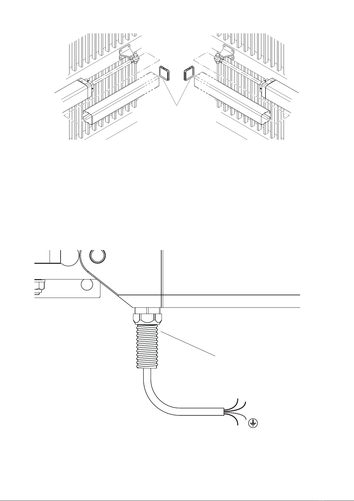
Pursuant to safety regulations in force, some types of installation require that the gate connection be earthed. During
installation, maintenance and repair, cut off power supply before accessing to live parts.
Also disconnect buffer batteries, if any are connected.
The electrical installation and the operating logic must comply with the regulations in force. The leads fed with different
voltages must be physically separate, or they must be suitably insulated with additional insulation of at least 1 mm.
The leads must be secured with an additional fixture near the terminals.
During installation, maintenance and repair, interrupt the power supply before opening the lid to access the electrical parts
Check all the connections again before switching on the power. The unused N.C. inputs must be bridged.
WASTE DISPOSAL
As indicated by the symbol shown, it is forbidden to dispose this product as normal urban waste as some parts might be
harmful for environment and human health, if they are disposed of incorrectly.
Therefore, the device should be disposed in special collection platforms or given back to the reseller if a new and similar
device is purchased. An incorrect disposal of the device will result in fines applied to the user, as provided for by regu-
lations in force.
Descriptions and figures in this manual are not binding. While leaving the essential characteristics of the product unchanged, the
manufacturer reserves the right to modify the same under the technical, design or commercial point of view without necessarily
update this manual.
Important
• Before installing the operator read these instructions.
• Use of a HYDRO product for any application not described in this instruction manual is prohibited.
• The user must be instructed on the use of the automation system.
• The user must be consigned the instruction manual.
• All CAB products are insured against damage or injury caused by manufacturing defects under the essential condi-
tion that the operator has the CE marking and all genuine CAB components are installed.
General Information
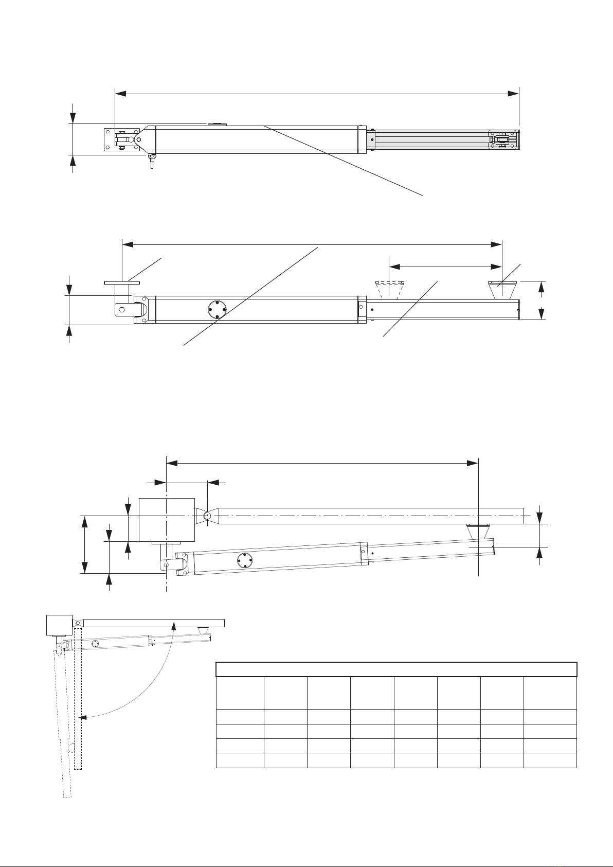
Hydraulic operator suitable for swinging gates, available in two different versions.
HD.80 230V 230V version-reversible- electric lock is needed
HD.80 115V 115V version-reversible- electric lock is needed
All the versions are provided with hydraulic slow down adjustable during closing phase and fixed during opening phase.
It is necessary to use the whole stroke, complying with the specified installation geometry.
12

Preliminary Checks
For the gate automation to work properly, the actual gate must have the following characteristics:
- it must be robust and rigid.
- the hinges must have only limited play and provide smooth and gentle gate movements.
- the whole height of the wings must be in contact when closed.
Gate Stops
If they are not already provided, install gate stops on the opening and closing stroke limits (Fig.3) regardless of the type
of operator being installed.
The mechanical stop in close position is compulsory because of the particular characteristics of the hydraulic actuators.
Installing the automation system
1 Establish the height of the automation from the ground (preferably as close to the centre of the wing as possible and
along a solid cross rail).
Remember that under the operator there is a vent hole and in certain conditions (e.g. rain or snow) it may draw liquid
into the automation. For this reason it is best not to install the operator too close to the ground.
2 Weld or otherwise anchor plate P in place, see installation distances (Fig.2) and the installation diagram (Fig.5):
- insert pin P in bracket P as in the figure
- insert the fork F of the HD.80 into the bracket P
- lock everything in place by washer R and self-locking nut D
- remove the vent plug VS with its gasket RS. (see note “Vent plug”)
Observe the distances given in the tables at fig. 2, correcting the length of the plate if necessary. In some cases a
recess may have to be made in the post.
It is essential that the installation distances are respected for the operator to work correctly.
With reference to the installation tables note that:
For the wing to open 90°: A+B must be equal to the operator stroke
For the wing to open more than 90°: A+B must be less than the operator stroke.
Keep the length differences within 40mm. Over this difference the wing movement becomes uneven. When reducing
lengths A and B , increase the wing speed.
Comply with all statutory regulations.
3 Slide out the ram shaft completely and then slide back in by approx. 10 mm. Lock the operator in place.
Always leave a safety overrun of 10 mm in both the closing and opening strokes. The stroke length given in the techni-
cal data and installation tables has already been reduced by the necessary 20 mm.
4 Make sure the operator is kept perfectly level and mark the point where the bracket will be attached to on the wing.
Temporarily weld or bolt the bracket in place as shown in Fig.6.
5 Release the operator and swing the gate by hand to check it moves freely to fully open and stops on the gate stop.
The wing must move smoothly and evenly.
6 Anchor the bracket permanently.
NOTE: Vent plug.
Next to the vent a dead hole has been provided where the plug and gasket can be kept for future use.
On removing the plug and during the first operator manoeuvres a small quantity of oil may leak out. This is perfectly
normal and should not be considered a fault.
Manual and emergency gate operation
Being reversible, the motors HD.80 can be released simply by unlocking the electric lock, after that the leaf can be
operated manually.
Slowly push the wing by its outer end, accompanying it all the way to the gate stop.
The operation can be made easier by loosening the release valve (Fig.9).
Adjusting the thrust
The operator is equipped with anti-squash by-pass valve that limit the thrust on the wing when it meets an obstacle.
Once the obstacle is removed the wing will continue its stroke for the work time set by the control unit.
• Open the protective cover (Fig.7) and use a 6 mm hexagonal key to adjust the thrust (Fig.9).
• There are two adjustable valves, one governs the opening thrust (Open), the other governs the closing thrust (Close).
• Turn the valve towards + to increase the thrust on the wing and vice-versa (i.e. towards - ) to reduce the thrust.
CAUTION! This adjustment is directly linked to the safety level of the automation.
Make sure that the thrust applied on the wing complies with statutory regulations.
Slow down adjustement
all the versions are provided with slow down in close and open position for a slower movement during the last seconds
of the maneuver.
ìThe slow down in both direction starts in the last part of the stroke, so it is very important to use the whole stroke and
respect the indicated installation geometry.
13

ìThe slow down in close position can be adjusted by means of the dedicated valve (Fig.11).
ìRemove the protection cap and using an allen key by 3 mm:
ì-loosen ( counterclockwise rotation) the valve in order to increase the slow down speed
ì-tighten (clockwise rotation) the valve in order to reduce the slow down speed.
Never force the adjusting valve
The protective covers
After adjusting the slowdown the covers can be replaced (Fig.11).
Take great care in ensuring that the drain hole faces the ground.
Wiring
The operator is supplied with the wiring cable already installed and wired (Fig.12). To connect it to the control unit see
the diagram and instructions for the control unit.
The power cable is best protected by a 12mm spiral sheath that has to be inserted in the coupling provided.
An earth connection is compulsory.
Topping up/changing oil
The oil level in all hydraulic operators must be periodically checked.
To top up the oil first shut-off the mains power to the system and then remove the 4 screws on the terminal block, which
also acts as oil cap.
The oil level, when the stem is totally inside (open leaf) must reach the cavity showed in fig.10
Only use D.OIL.
14

Hydro
User’s handbook
Safety rules
• Do not stand in the movement area of the gate.
• Do not let children play with controls and near the gate.
• Should operating faults occur, do not attempt to repair
the fault but call a qualified technician.
Manual and emergency gate operation
Being reversible, the motors HD.80 can be released simply
by unlocking the electric lock, after that the leaf can be
operated manually.
Slowly push the wing by its outer end, accompanying it all
the way to the gate stop.
The operation can be made easier by loosening the release
valve.
Maintenance
• It is mandatory not to carry out extraordinary maintenance
or repairs as accidents may be caused.
These operations must be carried out by qualified person-
nel only.
• Periodically check safety components and any other parts
of the system that may become hazardous if worn.
Waste disposal
If the product must be dismantled, it must be disposed ac-
cording to regulations in force regarding the differentiated
waste disposal and the recycling of components (metals,
plastics, electric cables, etc..). For this operation it is advis-
able to call your installer or a specialised company.
Open the protective cover
6
In case the manual operation proves difficult, rotate the highlighted
screw toward the + (maximum one rotation). Before to go back to the
automatic functioning bring the screw to the original position.
22

14
4
8
7
17
1
5
2
6
3
11
10
15
12
16
9
13
25

HYDRO HD.80
N° Denominazione - Description - Bezeichnung - Dénomination - Denominación - Określenie Cod.
1Fondello End plåate Bodenscheibe Fond Fondo Spód 439500103
2Serbatoio Tank Tank Réservoir Depósito Zbiornik 566700186
3Tappo End cap Deckel Bouchon Tapón Zatyczka 583700206
4
Motore 230V Motor 230V Motor 230V Moteur 230V Motor 230V Silnik 230V 358700051
Motore 115V Motor 115V Motor 115V Moteur 115V Motor 115V Silnik 115V 358700052
5Pompa Pump Pumpe Pompe Bomba Pompa F863400641
6Distributore Distributor Verteiler Distributeur Distribuidor Dystrybutor 339600040
7Testa rallentam. Slowdown head Kopf Verlangs. Tête ralentiss. Cabeza decel. Przód zwalniania 439600109
8Testa rallentam. Slowdown head Kopf Verlangs. Tête ralentiss. Cabeza decel. Przód zwalniania 339600039
9Stelo Ram shaft Schaft Tige piston Vástago Trzpień 363300073
10 Testa snodo Pivot head Gelenkkopf Tête articul. Cabeza articul. Przód przegubu F8780006
11 Tubo Barrel Rohrleitung Tube Tubo Rura F886800916
12
Copristelo Ram sleeve Schaftdeckel Carter piston Cubrevástago Osłona trzpienia
586800215
13 Cavo alimentaz. Power cable Stromkabel. Câble alim. Cable alimen. Przewód zasilania F817100305
14
Condensatore 10µF Capacitor 10µF Kondensator 10µF Condensateur 10µF Condensador 10µF Kondensator 10µF F823400331
Condensatore 36µF Capacitor 36µF Kondensator 36µF Condensateur 36µF Condensador 36µF Kondensator 36µF F8234030
15 D.OIL (2 L) D.OIL (2 L) D.OIL (2 L) D.OIL (2 L) D.OIL (2 L) D.OIL (2 L) 9603002
16 Blister Blister Blister Blister Blister Blister 408900069
17 Kit Guarnizioni Seals kit Kit Dichtung Garniture Set Set Juntas Uszczelka 9688249

Dichiarazione di Conformità UE (DoC)
Nome del produttore: CAB
Indirizzo: Via della Tecnica, 10 (z.i.) - 36010 Velo d’Astico (VI) - Italia
Persona autorizzata a costruire la documentazione tecnica: CAB
Dichiara che il documento è rilasciato sotto la propria responsabilità e appartiene al
seguente prodotto:
Tipo di prodotto: Attuatore oleodinamico 230Vac per cancelli a battente
Modello/Tipo: HD.80 Accessori: N/A
Il prodotto sopraindicato risulta conforme alle disposizioni imposte dale seguenti
direttive:
Direttiva 2014/30/EU
Direttiva 2011/65/EU
Direttiva 2014/35/EU
Sono state applicate le norme armonizzate e le speciche tecniche descritte di seguito:
EN 61000-6-2:2005, EN 61000-6-3:2007 + A1:2011
EN 60335-1:2012 + A11:2014; EN 60335-2-103:2015
50581:2012
Il Certicato di Conformità di questo documento corrisponde all'ultima revisione
disponibile al momento della stampa e può risultare differente per esigenze editoriali
dall'originale disponibile presso il produttore.
Benincà Luigi, Responsabile legale.
Velo d’Astico, 14/06/2018.
UE Declaration of Conformity (DoC)
Manufacturer's name: CAB
Address: Via della Tecnica, 10 (z.i.) - 36010 Velo d’Astico (VI) - Italia
Person authorised to draft the technical documentation: CAB
Declare that the DOC is issued under our sole responsibility and belongs to the fol-
lowing product:
Product type: Hydraulic actuator 230Vac for swing gates
Model/type: HD.80 Accessories: N/A
The object of the declaration described above is in conformity with the relevant Union
harmonization legislation:
Directive 2014/30/EU
Directive 2011/65/EU
Directive 2014/35/EU
The following harmonized standards and technical specications have been applied:
EN 61000-6-2:2005, EN 61000-6-3:2007 + A1:2011
EN 60335-1:2012 + A11:2014; EN 60335-2-103:2015
50581:2012
The certicate of conformity in this document corresponds to the last review available
at the time of printing and could differ for editorial requirements from the original
available from the manufacturer.
Benincà Luigi, Legal Ofcer.
Velo d’Astico, 14/06/2018.
EG-Konformitätserklärung (DoC)
Name des Herstellers: CAB
Adresse: Via della Tecnica, 10 (z.i.) - 36010 Velo d’Astico (VI) - Italia
Zur Erstellung der technischen Dokumentation berechtigte Person:
CAB
Erklärt, dass das Dokument unter alleiniger Verantwortung herausgegeben wurde und
zu dem folgenden Produkt ge-hört:
Produkttypus: Hydraulischer 230Vac-Antrieb für Drehtoranlagen
Modell/Typus: HD.80 Zubehör: N/A
Das oben genannte Produkt stimmt mit den Vorschriften der folgenden Richtlinien
überein:
Richtlinie 2014/30/EU
Richtlinie 2011/65/EU
Richtlinie 2014/35/EU
Die harmonisierten Normen und technischen Spezikationen, die unten beschrieben
werden, wurden angewandt:
EN 61000-6-2:2005, EN 61000-6-3:2007 + A1:2011
EN 60335-1:2012 + A11:2014; EN 60335-2-103:2015
50581:2012
Die in diesem Dokument vorliegende Konformitätserklärung entspricht der neuesten
zum Druckzeitpunkt erhältlichen Revision und könnte aufgrund von verlegerischen
Gründen vom beim Hersteller erhältlichen Original abweichen.
Benincà Luigi, Rechtsvertreter.
Velo d’Astico, 14/06/2018.
Déclaration CE de conformité (DoC)
Nom du producteur : CAB
Adresse : Via della Tecnica, 10 (z.i.) - 36010 Velo d’Astico (VI) - Italia
Personne autorisée à construire la documentation technique : CAB
Nous déclarons que le document est délivré sous notre propre responsabilité et qu'il
appartient au produit suivant :
Type de produit : Actionneur oléodynamique 230Vac pour portails battants
Modèle/Type: HD.80 Accessoires : N/A
Le produit mentionné ci-dessus est conforme aux dispositions établies par les direc-
tives suivantes :
Directive 2014/30/EU
Directive 2011/65/EU
Directive 2014/35/EU
Les normes harmonisées et les spécications techniques décrites ci-dessous ont été
appliquées :
EN 61000-6-2:2005, EN 61000-6-3:2007 + A1:2011
EN 60335-1:2012 + A11:2014; EN 60335-2-103:2015
50581:2012
Le certicat de conformité présent dans ce document correspond à la dernière révision
disponible au moment de l’impression et pourrait différer pour des exigences éditoriales
de l’original disponible chez le constructeur.
Benincà Luigi, Représentant Légal
Velo d’Astico, 14/06/2018.

CAB è un marchio di AUTOMATISMI BENINCA’ SpA - Via della Tecnica,10 ZI - 36010 Velo d’Astico (VI) (Italia) - Tel. 0445 741215 - Fax 0445 742094
Other manuals for HD.80
1
Table of contents
Other CAB Gate Opener manuals