CAB HYDRO HD.3524E User manual

CL8542450
10/2018 rev 2
HYDRO
HD.3524E - HD.3524E AC
HD.5024E - HD.5024E AC
IT
EN
DE
FR
ES
PL

2
HD.5024 (390)
αA(mm) B(mm) C (mm) D(mm) Z(mm) T* (s)
90° 195 195 145 50 100 20
100° 180 180 145 50 100 20
110° 130 170 120 50 100 18
α
HD.3524 (270)
αA(mm) B(mm) C (mm) D(mm) Z(mm) T* (s)
90° 135 135 85 50 75 14
100° 125 125 75 50 75 14
110° 115 115 65 50 75 13
*Tempo apertura indicativo, escluso rallentamento - *Indicative opening time, excluded slowdown - *Hinweisende öffnungszeit, ausschließliches Verlangsamen
*Temps indicatif d’ouverture, ralentissement exclu - *Tiempo indicativo de abiertura, deceleración excluido - *Wskazujący czas otwierania, wyłączył zwalniają
1177 (HD.3524)
1417 (HD.5024)
120
Mettere a livello.
Level.
Nivellieren.
Mettre de niveau.
Nivelar.
Ustawić na wysokości
Corsa.
Stroke.
Hub.
Course.
Carrera.
Posuw.
Interasse ancoraggi.
Distance between axes of anchoring bolts.
Die maximale Öffnung der Verankerungen.
Entraxe ancrages.
Distancia entre ejes ancrajes.
Współośowość elementów mocujących.
1117 (HD.3524)
1357 (HD.5024)
85
270 (HD.3524)
390 (HD.5024)
PS
110
(135 HD.5024)
B
A
CZ
D
1117 (HD.3524)
1357 (HD.5024)
1
2
25

3
Arresto in chiusura.
Stop when closing.
Endanschlag zur Schließung.
Arrêt en fermeture.
Tope de cierre.
Chwytak blokujący podczas zamykania.
Arresto in apertura.
Stop when opening.
Endanschlag zur Öffnung.
Arrêt en ouverture.
Tope en apertura.
Chwytak blokujący podczas otwierania.
3
4
A B
C D
E
5
7° max

4
V
C
D
R
P
V
D
Tagliare a misura e saldare
Cut to size and weld
Auf Maß zuschneiden und schweißen
Couper à la bonne mesure et souder
Cortar a medida y soldar
Wyciąć według rozmiaru i zespawać
Grasso
Grease
Fett
Graisse
Grasa
Smar
8
max. 290mm (HD.35)
max. 410mm (HD.50)
min. 20mm
67
Anta sinistra
Left-hand wing
Linker Flügel
Vantail gauche
Hoja izquierda
Skrzydło lewe
Anta destra
Right-hand wing
Rechter Flügel
Vantail droit
Hoja derecha
Skrzydło prawe

5
Anta sinistra
Left-hand wing
Linker Flügel
Vantail gauche
Hoja izquierda
Skrzydło lewe
Anta destra
Right-hand wing
Rechter Flügel
Vantail droit
Hoja derecha
Skrzydło prawe
11
12
9
1
2
10

6
3
4
2
5
1
6
3x1,5 min
230Vac
2
1
2x1,5
2x1
2x1
4x1,5
4x1,5
4x1
RG 58
7
14
Guaina spiralata ø12
ø12 spiral sheath
Spiralmantel ø12
Gaine spiralée ø12
Vaina corrugada ø12
Osłona spiralna ø12
KRBGW
K
R
B
G
W
ENC-
ENC
ENC+
M+24
M-24
Bianco White Weiß Blanc Blanco Biały
Verde Green Grün Vert Verde Zielony
Marrone Brown Braun Brun Marrón Brązowy
Rosso Red Rot Rouge Rojo Czerwony
Nero Black Schwarz Noir Negro Czarny
13

7
15
Livello olio
Oil level
Ölstand
Niveau d’huile
Nivel de aceite
Poziom oleju

11
EN
ENG WARNING
GENERAL INFORMATIONS
The product shall not be used for purposes or in ways other than those for which the product is intended for and as described
in this manual.
Incorrect uses can damage the product and cause injuries and damages.
The company shall not be deemed responsible for the non-compliance with a good manufacture technique of gates as well
as for any deformation, which might occur during use.
Keep this manual for further use.
INSTALLER GUIDE
This manual has been especially written to be use by qualified fitters.
Installation must be carried out by qualified personnel (professional installer, according to EN 12635), in compliance with
Good Practice and current code.
Make sure that the structure of the gate is suitable for automation.
The installer must supply all information on the automatic, manual and emergency operation of the automatic system and
supply the end user with instructions for use.
GENERAL WARNINGS
Packaging must be kept out of reach of children, as it can be hazardous.
For disposal, packaging must be divided the various types of waste (e.g. carton board, polystyrene) in compliance with
regulations in force.
Do not allow children to play with the fixed control devices of the product.
Keep the remote controls out of reach of children.
This product is not to be used by persons (including children) with reduced physical, sensory or mental capacity, or who are
unfamiliar with such equipment, unless under the supervision of or following training by persons responsible for their safety.
Apply all safety devices (photocells, safety edges, etc.) required to keep the area free of impact, crushing, dragging and
shearing hazard.
Bear in mind the standards and directives in force, Good Practice criteria, intended use, the installation environment, the
operating logic of the system and forces generated by the automated system.
Installation must be carried out using safety devices and controls that meet standards EN 12978 and EN 12453.
Only use original accessories and spare parts, use of non-original spare parts will cause the warranty planned to cover the
products to become null and void.
All the mechanical and electrical parts composing automation must meet the requirements of the standards in force and
outlined by CE marking.
ELECTRICAL SAFETY
An omnipolar switch/section switch with remote contact opening equal to, or higher than 3mm must be provided on the
power supply mains.
Make sure that before wiring an adequate differential switch and an overcurrent protection is provided.
Pursuant to safety regulations in force, some types of installation require that the gate connection be earthed.
During installation, maintenance and repair, cut off power supply before accessing to live parts.
Also disconnect buffer batteries, if any are connected.
The electrical installation and the operating logic must comply with the regulations in force.
The leads fed with different voltages must be physically separate, or they must be suitably insulated with additional insulation
of at least 1 mm.
The leads must be secured with an additional fixture near the terminals.
During installation, maintenance and repair, interrupt the power supply before opening the lid to access the electrical parts
Check all the connections again before switching on the power.
The unused N.C. inputs must be bridged.
WASTE DISPOSAL
As indicated by the symbol shown, it is forbidden to dispose this product as normal urban waste as some parts might be
harmful for environment and human health, if they are disposed of incorrectly.
Therefore, the device should be disposed in special collection platforms or given back to the reseller if a new and similar
device is purchased.
An incorrect disposal of the device will result in fines applied to the user, as provided for by regulations in force.
Descriptions and figures in this manual are not binding.
While leaving the essential characteristics of the product unchanged, the manufacturer reserves the right to modify the same under the
technical, design or commercial point of view without necessarily update this manual.

12
IMPORTANT
• Before installing the operator read these instructions.
• Use of a HYDRO product for any application not described in this instruction manual is prohibited.
• The user must be instructed on the use of the automation system.
• The user must be consigned the instruction manual.
• All CAB products are insured against damage or injury caused by manufacturing defects under the essential condition that the operator has the
CE marking and all genuine CAB components are installed.
1) GENERAL INFORMATION
Hydraulic operator for swing gates, available in various versions:
MODEL Door leaf weight (kg)
Door leaf width
(m) Stroke length (mm) Type of lock
HD.3524E 500 3,5 270 ¢
HD.3524E AC 500 3,5 270 vw
HD.5024E 500 5 390 ¢
HD.5024E AC 500 5 390 vw
LEGENDA DESCRIZIONE
¢Reversible (Requires electric lock)
vw One-way
“HD.3524E AC” and “HD.5024E AC” models are equipped with hydraulic lock on the opening stroke and do not require an electric lock* since the
operator locks the wing shut when the motor is not in running.
Models without hydraulic lock on opening stroke
(HD.3524E - HD.5024E)
always require an electric lock to guarantee the wing is locked shut mechanically.
All models are equipped with adjustable hydraulic slowdown on the closing stroke.
*For wings longer than 2m an electric lock is recommended even on one-way models.
All models are equipped with Encoder function used both for slowdown phase management and as an anti-crushing sensor. For the correct use of
these functions, it is essential to use the HYBRA 24 central control unit, refer to the instructions supplied with the central unit for further information.
2) TECHNICAL DATA
MODEL HD.3524E HD.3524E AC HD.5024E HD.5024E AC
Power supply
24 Vdc
Motor
240 W
Absorbed current
5 A
Protection rating
IP55
Oil
BIO OIL
Operating temp.
-20°C/+50°C
Hydraulic lock Reversible Opening and closing Reversible Opening and closing
Thrust 4000 N
Pump delivery 1.4l/min 2800rpm
Rod speed 2 cm/s
Working stroke 270mm 390mm
Stroke time 14s 20s
N° cons.ve manoeuv. Intensive use
Braking Electronic
Max gate 3.5m
electric lock
3.5m
(from 2 to 3.5m electric lock)
5m
electric lock
5m
(from 2 to 3.5m electric lock)
3) PRELIMINARY CHECKS
For the gate automation to work properly, the actual gate must have the following characteristics:
- it must be robust and rigid.
- the hinges must have only limited play and provide smooth and gentle gate movements.
- the whole height of the wings must be in contact when closed.
4) OVERALL DIMENSIONS (FIG.1)
Fig. 1 shows the main overall dimensions for the various models, values are expressed in mm.
5) INSTALLATION MEASURES
Fig. 2 shows the main installation values and the approximate opening times.
6) GATE STOPS
If they are not already provided, install gate stops on the opening and closing stroke limits (Fig.3) regardless of the type of operator being installed.
The closed stop in particular is indispensable given the special characteristics of hydraulic operators. See “maintain stop” function in the instructions
for the control unit.
If there is no possibility of installing a stop in the opening, it is essential to apply the supplied mechanical lock rings to the stem (fig.4).
The number of rings to be applied depends on the installation values and the desired stop point, however, the X and Y terminals should be applied
as shown in Figure 4-D.

13
EN
7) INSTALLING THE AUTOMATION SYSTEM
1 Remove the vent screw VS with its RS gasket. (see fig.12 and note "Vent screw")
2 Before fixing the gear motor, the protection cover encoder circuit P (Figure 7) must be attached. The cover must be positioned on the side of the
motor facing the gate, therefore the position is different if the gear motor is to be placed on the left or right door.
3 Establish the height of the automation from the ground (preferably as close to the centre of the wing as possible and along a solid cross rail).
Remember that under the operator there is a vent hole (fig.12) and in certain conditions (e.g. rain or snow) it may draw liquid into the automation.
For this reason it is best not to install the operator too close to the ground.
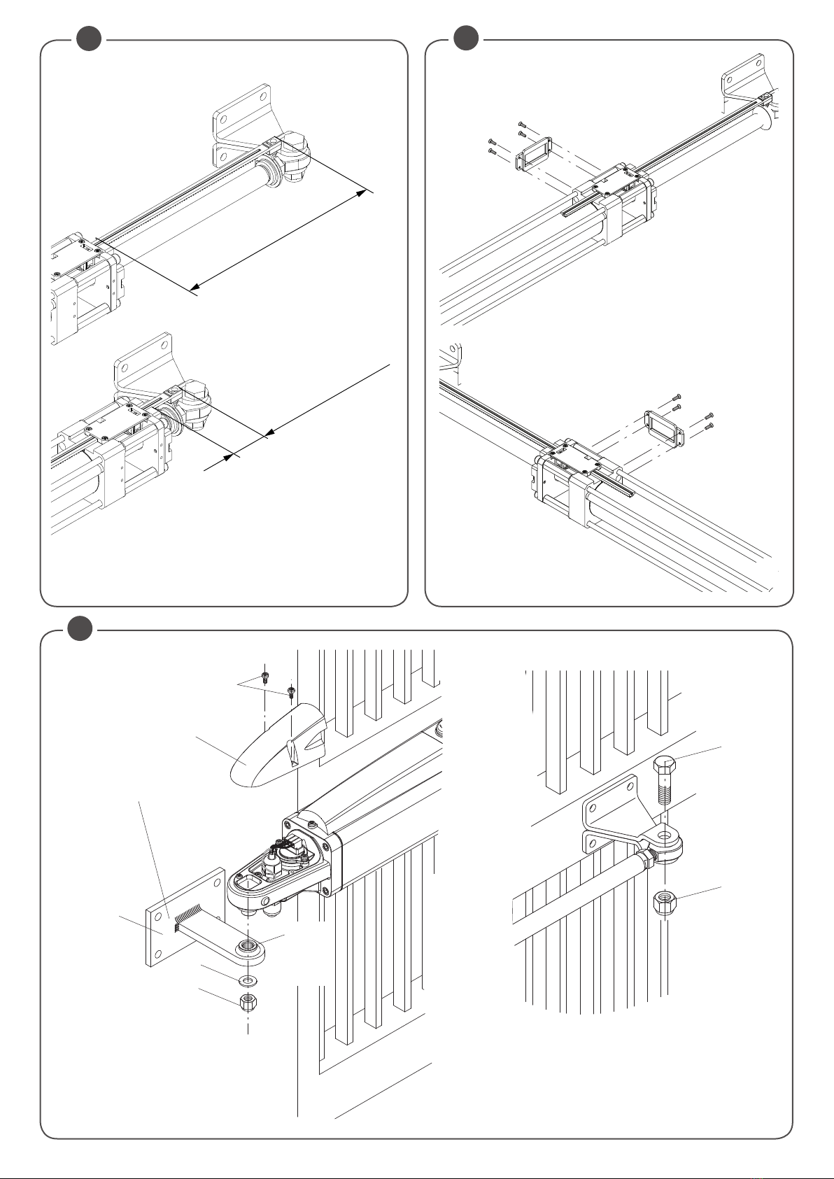
4 Weld or otherwise anchor plate P in place, see installation distances (Fig.2) and the installation diagram (Fig.8):
- remove screws V and cover C
- insert pin P in bracket P as in the figure
- lock everything in place by washer R and self-locking nut D
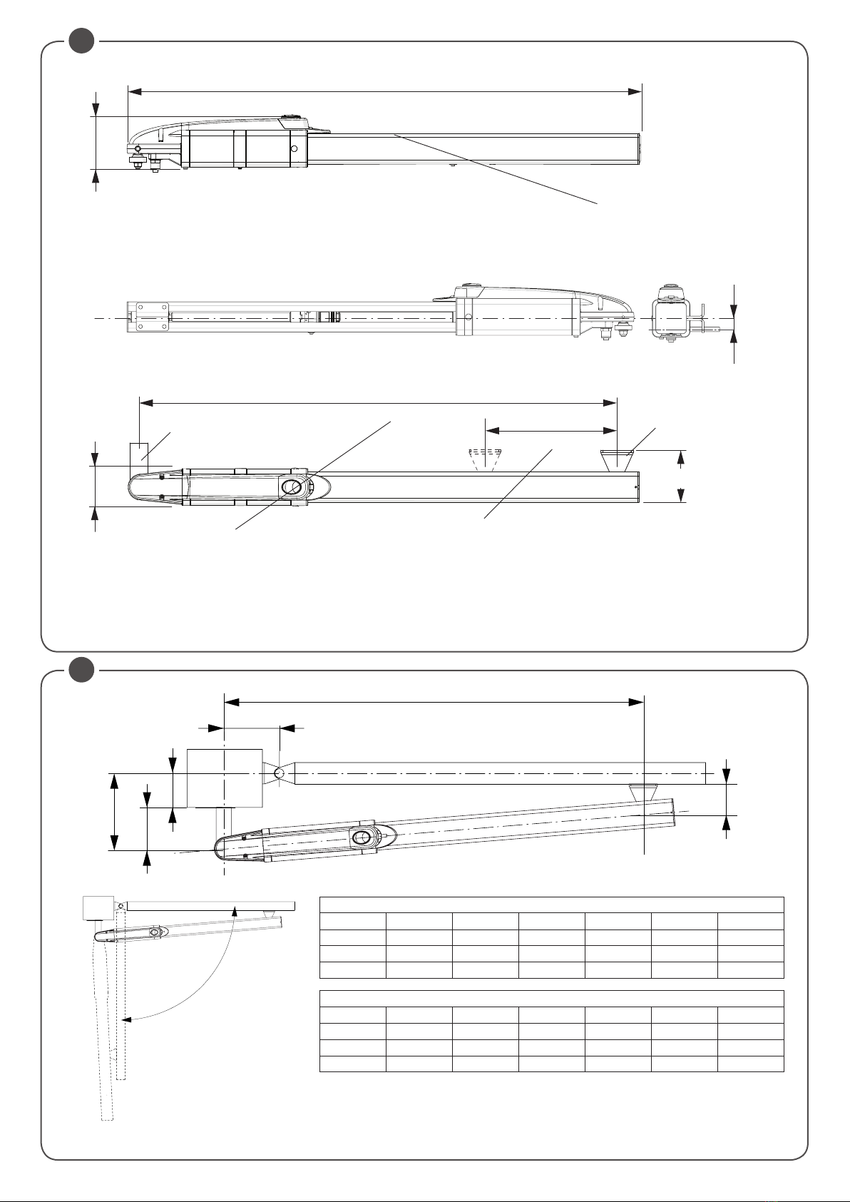
Observe the distances given in the tables at fig. 2, correcting the length of the plate if necessary. In some cases a recess may have to be made in the post.
It is essential that the installation distances are respected for the operator to work correctly.
With reference to the installation tables note that:
For the wing to open 90°: A+B must be equal to the operator stroke
For the wing to open more than 90°: A+B must be less than the operator stroke.
Keep the length differences within 40mm. Over this difference the wing movement becomes uneven. When reducing lengths A and B , increase the wing speed.
Comply with all statutory regulations.
5 Release the operator (see section “manual gate operation”)
Normally the gear motor is supplied already unlocked.
6 Slide out the ram shaft completely and then slide back in by approx. 10 mm. Lock the operator in place (fig.4).
Always leave a safety overrun of 10 mm in both the closing and opening strokes. The stroke length given in the technical data and installation tables
has already been reduced by the necessary 20 mm.
Before proceeding with the fixing of the actuator on the door check that the values measured on the Encoder rack, as shown in Fig. 6 are respected.
7 Make sure the operator is kept perfectly level and mark the point where the bracket will be attached to on the wing.
Temporarily weld or bolt the bracket in place as shown in Fig.8.
A horizontal position of the actuator is always preferable, but if necessary, the joints on the brackets allow for good operation even if tilted slightly,
as shown in Fig.5.
8
Release the operator and swing the gate by hand to check it moves freely to fully open and stops on the gate stop. The wing must move smoothly and evenly.
9 Anchor the bracket permanently.
NOTE: Vent plug (fig.12).
Next to the vent a dead hole has been provided where the plug and gasket can be kept for future use. On removing the plug and during the first opera-
tor manoeuvres a small quantity of oil may leak out. This is perfectly normal and should not be considered a fault.
8) MANUAL AND EMERGENCY GATE OPERATION (FIG.9-10)
If there is a power failure or malfunction the wings can be moved by hand as follows:
Models with hydraulic lock (i.e. HD.35 C -HD.35 AC - HD.50 AC):
• Use the special key supplied with the operator to open the protective cover of the release mechanisms (Fig.9).
• Turn the knob anticlockwise to disengage the automation. (Fig.10)
• The wing can now be opened and closed manually.
• To engage the automation turn the knob anticlockwise.
• Lock the cover shut.
Models without hydraulic lock (i.e. HD.35 - HD.45 - HD.50):
Since these models are reversible, simply open the electric lock and the wing can be moved manually.
Slowly push the wing by its outer end, accompanying it all the way to the gate stop. The movement may be made easier by slackening the release knob.
9) ADJUSTING THE THRUST
The actuator push force adjustment is performed electronically from the central control unit.
CAUTION! This adjustment is directly linked to the safety level of the automation.
Make sure that the thrust applied on the wing complies with statutory regulations.
10) THE PROTECTIVE COVERS (FIG.11)
Take great care in ensuring that the drain hole faces the ground.
11) WIRING (FIG.13)
The operator is supplied with the wiring cable already installed and wired (Fig.13). To connect it to the control unit see the diagram and instructions for
the control unit. The power cable is best protected by a 12mm spiral sheath that has to be inserted in the coupling provided.
12) TOPPING UP/CHANGING OIL (FIG.15)
The oil level in all hydraulic operators must be periodically checked.
For normal use, it is recommended to replace the oil every 5 years, for particularly intensive use, replacement is preferable every 2/3 years.
For refilling, after disconnecting the system power supply, simply remove the two V screws securing the terminal block, remove the three H screws
securing the C plastic cover and remove the T cap. The level should not exceed the quantity shown in Fig.15.
CAUTION!: Always shut-off the mains power before working on the gate
Only use BIO OIL.
13) WIRE DIAGRAM (FIG.14)
Legend:
1 Hydro 24V geared motor
2 Photocells
3 Key selector or digital keyboard
4 Beacon
5 Antenna
6 Control unit.
7 Electric lock
N.B.: The power cables must be kept separated from the auxiliary cables.
IMPORTANT: Installation of an electric lock is essential on models without hydraulic lock or if the wing is over 2 m long

26
1
2
33
14
4
3
5
7
812
26
27
28
32
24
18
13
9
10
11
15
16
17
19
6
AB
D
F
C
25
31
30
E
G
20
H
21
23
29
22
15
34

27
BTubo per HD.35/HD.35 C/HD.35 AC/HD.45 - Barrel - Rohrleitung - Tube - Tubo - Rura C5868003
Tubo per HD.50/HD.50 AC - Barrel - Rohrleitung - Tube - Tubo - Rura C5868005
ABarra M6 per HD.35/HD.35 C/HD.35 AC/HD.45 - M6 rod- Stange M6- Barre M6- Barra M6- Drążek M6 CF8954012
Barra M6 per HD.50/HD.50 AC - M6 rod- Stange M6 - Barre M6- Barra M6- Drążek M6 CF8954013
CCanna per HD.35/HD.35 C/HD.35 AC/HD.45 - Rod housing- Rohr - Canne- Conducto - Tuleja CF8868002
Canna per HD.50/HD.50 AC - Rod housing- Rohr - Canne- Conducto - Tuleja CF8868003
DStelo per HD.3524 - Ram shaft - Schaft - Tige piston- Vástago - Trzpień CF8829008
Stelo per HD.5024 - Ram shaft - Schaft - Tige piston- Vástago - Trzpień CF8829007
E
Copristelo per HD.35/HD.35 C/HD.35 AC/HD.45 - Ram sleeve - Schaftdeckel - Carter piston - Cubrevástago- Osłona trzpienia
C5868000
Copristelo per HD.50/HD.50 AC - Ram sleeve - Schaftdeckel - Carter piston - Cubrevástago- Osłona trzpienia C5868001
G
Staffa Anteriore per HD.35/HD.35 C/HD.35 AC/HD.45 - Gate bracket - Vord. Bügel - Bride avant - Estribo anterior - Zaczep Przedni
CF8819030
Staffa Anteriore
per
HD.50/HD.50 AC - Gate bracket
-
Vord. Bügel
-
Bride avant
-
Estribo anterior
-
Zaczep Przedni CF8819033
HYDRO
N° Denominazione - Description - Bezeichnung - Dénomination - Denominación - Określenie Cod.
1Carter morsettiera Terminal housing Gehäuse Carter bornier Cárter terminal Karter CF8144101
2Connettore Connector Verbinder Connecteur Conector Łącznik CF8830092
3
Carter Mobile + Serratura
Cover + Lock
Bew. Gehäuse + Schloss
Carter mobile + Serrure
Cárter móvil + Cerradura
Karter Ruchomy + Zamek
C3747000
4
Serratura
Lock
Schloss
Serrure
Cerradura
Zamek
CF8765090
5Carter Fisso Housing Festes Gehäuse Carter fixe Cárter fijo Karter Stały CF8144100
6Manopola Sblocco Release knob Entrieg.knauf Poignée déblocage Pomo desbloqueo Pokrętło odbl. CF8621021
7Piastra muro Wall plate Wandplatte Platine mur Placa de muro Płyta ścienna 9623060
8Staffa posteriore Wall bracket Hinterer Bügel Patte arrière Estribo poster. Zaczep tylny CF8819031
9Fondello End plate Bodenscheibe Fond Fondo Spód C3395020
10 Snodo Pivot Gelenk Articulation Articulación Przegub CF8780200
11 PG11 PG11 PG11 PG11 PG11 PG11 CF8646011
12 RPG112 RPG112 RPG112 RPG112 RPG112 RPG112 CF8516012
13 Perno snodo Pivot lock pin Gelenkbolzen Pivot articul. Perno articul. Sworzeń przegubu CF8621022
14 Tappo olio Oil cap Ölstopfen Bouchon huile Tapón de aceite Korek wlewu oleju CF8837055
15 Serbatoio Tank Tank Réservoir Depósito Zbiornik C5667013
16 Motore Motor Motor Moteur Motor Silnik CF8587100
17 Flangia motore Motor flange Motorflansch Bride moteur Brida del motor Kołnierz silnika C5396212
18 Pompa Pump Pumpe Pompe Bomba Pompa CF8634005
19 Giunto Joint Verbindung Joint Junta Złącze CF8424002
20 Flangia anteriore Flange Vord. Flansch Bride avant Brida anterior Kołnierz przedni C5396004
21 Testa Encoder Slowdown head Kopf Verlangs. Tête ralentiss. Cabeza decel. Przód zwalniania C4396202
22 Encoder Encoder Encoder Encoder Encoder Encoder C4362002
23 Piastra Encoder Encoder plate Encoder platte Platine Encoder Placa de Encoder Płyta Encoder CF8623250
24 Blister HD24 A20 Blister HD24 A20 Blister HD24 A20 Blister HD24 A20 Blister HD24 A20 Blister HD24 A20 C4089351
25 Testa snodo Pivot head Gelenkkopf Tête articul. Cabeza articul. Przód przegubu CF8780010
26 Tappo End cap Deckel Bouchon Tapón Zatyczka CF8837150
27 Cavo alimentaz. Power cable Stromkabel. Câble alim. Cable alimen. Przewód zasilania CF8171161
28 KIT guarnizioni SET Gaskets Dichtungen KIT KIT Garniture Juntas KIT SET Uszczelka 9688077
29 Flangia Posteriore Head flange Hint. Flansch Bride arrière Brida post Kołnierz Tylny CF8396200
30 Rondella flangiata Flange washer Geflanschte
Unterlegscheibe
Rondelle bridée Arandela bridada Podkładka
kołnierzowa CF8345033
31 Leva trascinamento Drag lever Antriebshebel Levier entrainement Palanca de arrastre
Dźwignia przesuwania
CF8540050
32 Tanica olio Oil tank Ölbehälter Réservoir huile Bidón de aceite Zbiornik oleju 9603002
33 Morsettiera 3 poli 3 poles Terminal
board
3-polige Klem-
menbrett
Bornier 3 pôles Terminal de 3 polos Listwa zaciskowa
3-biegunowa CF8585011
34 Morsettiera 2 poli 2 poles Terminal
board
2-polige Klem-
menbrett
Bornier 2 pôles Terminal de 2 polos Listwa zaciskowa
2-biegunowa CF8585012
F
Cremagliera HD.3524 EAC/HD.3524 E -
Rack - Rack - Grille - Rack - Stojak
C5272005
Cremagliera HD.5024 EAC/HD.5024 E -
Rack - Rack
-
Grille - Rack - Stojak
CF8272005
H
Distributore 3524 AC / 5024 AC - Distributor
- Verteiler
- Distributeur - Distribuidor - Dystrybutor
C4396232
Distributore 3524 / 5024 - Distributor
- Verteiler
- Distributeur - Distribuidor - Dystrybutor
C4396233

28
NORME DI SICUREZZA
• Non sostare nella zona di movimento delle ante.
•
Non lasciare che i bambini giochino con i comandi o in prossimità delle ante.
• In caso di anomalie di funzionamento non tentare di riparare il guasto
ma avvertire un tecnico specializzato.
MANOVRA MANUALE E D’EMERGENZA
In caso di mancanza dell’energia elettrica o di guasto, per azionare
manualmente le ante procedere come segue:
Modelli dotati di blocco idraulico
(HD.3524E AC - HD.5024E AC):
• Utilizzando la chiave personalizzata, fornita in dotazione con ogni at-
tuatore, aprire lo sportellino di protezione del meccanismi di sblocco
(Fig.1).
• Ruotare la manopola in senso antiorario per sbloccare l'automazione
(Fig.2).
• È ora possibile aprire/chiudere manualmente l'anta.
• Per ripristinare il funzionamento automatico, ruotare la manopola in
senso orario.
• Richiudere a chiave lo sportellino di protezione.
Modelli sprovvisti di blocco idraulico
(HD.3524E - HD.5024E AC):
Questi modelli, essendo reversibili richiedono semplicemente lo sgancio
dell'elettroserratura, dopodichè l'anta può essere manovrata manualmente.
Spingere con moderazione l'anta alla sua estremità, accompagnandola
per tutta la corsa.
La manovra può essere agevolata allentando la manopola di sblocco.
MANUTENZIONE
•
Controllare periodicamente l’efficienza dello sblocco manuale di emergenza.
• Astenersi assolutamente dal tentativo di effettuare riparazioni, potre-
ste incorrere in incidenti; per queste operazioni contattare un tecnico
specializzato.
•
Verificare periodicamente l’efficienza dei dispositivi di sicurezza e le altre
parti dell’impianto che potrebbero creare pericoli in seguito ad usura.
SMALTIMENTO
Qualora il prodotto venga posto fuori servizio, è necessario seguire
le disposizioni legislative in vigore al momento per quanto riguarda lo
smaltimento differenziato ed il riciclaggio dei vari componenti (metalli,
plastiche, cavi elettrici, ecc.); è consigliabile contattare il vostro installa-
tore o una ditta specializzata ed abilitata allo scopo.
ATTENZIONE
Tutti i prodotti CAB sono coperti da polizza assicurativa che risponde
di eventuali danni a cose o persone causati da difetti di fabbricazione,
richiede però la marcatura CE della ”macchina” e l’utilizzo di componenti
originali CAB.
Libro istruzioni per l’utilizzatore
User’s handbook
Aprire lo sportellino per acceddere alla manopola di sblocco
Open the protective cover to access the release knob
1: Ruotare in senso antiorario per sbloccare l'automazione e muovere
manualmente l'anta
2: Ruotare in senso orario per ripristinare il movimento automatico
1:
Turn anticlockwise to disengage the operator and move the wing manually
2: Turn clockwise to engage the operator
HYDRO
SAFETY RULES
• Do not stand in the movement area of the gate.
• Do not let children play with controls and near the gate.
• Should operating faults occur, do not attempt to repair the fault but call
a qualified technician.
MANUAL AND EMERGENCY GATE OPERATION
If there is a power failure or malfunction the wings can be moved by
hand as follows:
Models with hydraulic lock
(HD.3524E AC - HD.5024E AC):
• Use the special key supplied with the operator to open the protective
cover of the release mechanisms (Fig.1).
• Turn the knob anticlockwise to disengage the automation. (Fig.2)
• The wing can now be opened and closed manually.
• To engage the automation turn the knob anticlockwise.
• Lock the cover shut.
Models without hydraulic lock
(HD.3524E - HD.5024E AC):
Since these models are reversible, simply open the electric lock and the
wing can be moved manually.
Slowly push the wing by its outer end, accompanying it all the way to
the gate stop. The movement may be made easier by slackening the
release knob.
MAINTENANCE
• Every month check the good operation of the emergency manual release.
• It is mandatory not to carry out extraordinary maintenance or repairs
as accidents may be caused.
These operations must be carried out by qualified personnel only.
• Periodically check safety components and any other parts of the system
WASTE DISPOSAL
If the product must be dismantled, it must be disposed according to
regulations in force regarding the differentiated waste disposal and the
recycling of components (metals, plastics, electric cables, etc..). For this
operation it is advisable to call your installer or a specialised company.
WARNING
All CAB products are covered by insurance policy for any possible dam-
ages to objects and persons caused by construction faults under condi-
tion that the entire system be marked CE and only CAB parts be used.
1
2

31
Dichiarazione di Conformità UE (DoC)
Nome del produttore: Automatismi CAB Srl
Indirizzo: Via della Tecnica, 10 (z.i.) - 36010 Velo d’Astico
(VI) - Italia
Persona autorizzata a costruire la documentazione tecnica:
Automatismi CAB Srl
Tipo di prodotto: Attuatore oleodinamico 24Vadc per
cancelli a battente
Modello/Tipo: HD.35 - HD.35C - HD.35AC - HD.40L -
HD.50 - HD.50AC
Accessori: N/A
Il sottoscritto Luigi Benincà, in qualità di Responsabile Le-
gale, dichiara sotto la propria responsabilità che il prodotto
sopraindicato risulta conforme alle disposizioni imposte
dalle seguenti direttive:
Direttiva 2014/30/UE del Parlamento europeo e del Consiglio,
del 26 febbraio 2014, concernente l’armonizzazione delle legi-
slazioni degli Stati membri relative alla compatibilità elettro-
magnetica (EMCD), secondo le seguenti norme armonizzate:
EN 61000-6-2:2005, EN 61000-6-3:2007.
Direttiva 2011/65/UE del Parlamento europeo e del
Consiglio, dell’ 8 giugno 2011, sulla restrizione dell’uso
di determinate sostanze pericolose nelle apparecchiature
elettriche ed elettroniche (RoHS), secondo le seguenti
norme armonizzate:
EN 50581:2012
Benincà Luigi, Responsabile legale.
Velo d'Astico, 27/07/2017.
Il Certificato di Conformità di questo documento corrispon-
de all'ultima revisione disponibile al momento della stampa
e può risultare differente per esigenze editoriali dall'originale
disponibile presso il produttore.
Il Certificato di Conformità più completo e recente può
essere richiesto presso:
Automatismi CAB Srl - Velo d'Astico VI - Italy.
UE Declaration of Conformity (DoC)
Manufacturer's name: Automatismi CAB Srl
Address: Via della Tecnica, 10 (z.i.) - 36010 Velo d’Astico
(VI) - Italia
Person authorised to draft the technical documentation:
Automatismi CAB Srl
Product type: Hydraulic actuator 24Vdc for swing gates
Model/type: HD.35 - HD.35C - HD.35AC - HD.40L -
HD.50 - HD.50AC
Accessories: N/A
The undersigned Luigi Benincà, as the Legal Officer, de-
clares under his liability that the aforementioned product
complies with the provisions established by the following
directives:
Directive 2014/30/UE OF THE EUROPEAN PARLIA-
MENT AND OF THE COUNCIL of 26 February 2014, on
the harmonisation of the laws of Member States relating to
electromagnetic compatibility (EMCD), according to the
following harmonised regulations:
EN 61000-6-2:2005, EN 61000-6-3:2007 + A1:2011.
Directive 2011/65/EU of the European Parliament and
Council, dated 8 June 2011, on the restricted use of certain
hazardous substances in electrical and electronic devices
(RoHS), according to the following standards:
EN 50581:2012
Benincà Luigi, Legal Officer.
Velo d'Astico, 27/07/2017.
The certificate of conformity in this document corresponds
to the last review available at the time of printing and could
differ for editorial requirements from the original available
from the manufacturer.
The most recent and complete certificate of conformity can
be requested from:
Automatismi CAB Srl - Velo d'Astico VI - ITALY.
EG-Konformitätserklärung (DoC)
Name des Herstellers: Automatismi CAB Srl
Adresse: Via della Tecnica, 10 (z.i.) - 36010 Velo d’Astico
(VI) - Italia
Zur Erstellung der technischen Dokumentation berechtigte
Person: Automatismi CAB Srl
Produkttypus: Hydraulischer 24Vdc-Antrieb für Drehto-
ranlagen
Modell/Typus: HD.35 - HD.35C - HD.35AC - HD.40L -
HD.50 - HD.50AC
Zubehör: N/A
Der Unterzeichnete Luigi Benincà, in seiner Eigenschaft als
Rechtsvertreter, erklärt eigenverantwortlich, dass das oben
angegebene Produkt den durch die folgenden Richtlinien
vorgegebene Bestimmungen entspricht:
Richtlinie 2014/30/UE DES EUROPÄISCHEN PARLA-
MENTS UND DES RATES vom 26. Februar 2014 zur
Angleichung der Rechtsvorschriften der Mitgliedstaaten
über die elektromagnetische Verträglichkeit (EMCD),
gemäß nachstehenden Normen:
EN 61000-6-2:2005, EN 61000-6-3:2007 + A1:2011.
Richtlinie 2011/65/EU des Europäischen Parlaments
und des Rates vom 8. Juni 2011 zur Beschränkung der
Verwendung bestimmter gefährlicher Stoffe in Elektro- und
Elektronikgeräten (RoHS), gemäß den folgenden harmoni-
sierten Normen:
EN 50581:2012
Benincà Luigi, Rechtsvertreter.
Velo d'Astico, 27/07/2017.
Die in diesem Dokument vorliegende Konformitätserklärung
entspricht der neuesten zum Druckzeitpunkt erhältlichen
Revision und könnte aufgrund von verlegerischen Gründen
vom beim Hersteller erhältlichen Original abweichen.
Die neueste und vollständigste Konformitätserklärung kann
bei folgender Adresse angefordert werden: Automatismi
CAB Srl - Vel d'Astico VI - ITALY.
Déclaration CE de conformité (DoC)
Nom du producteur : Automatismi CAB Srl
Adresse : Via della Tecnica, 10 (z.i.) - 36010 Velo d’Astico
(VI) - Italia
Personne autorisée à construire la documentation technique
: Automatismi CAB Srl
Type de produit : Actionneur oléodynamique 24Vdc pour
portails battants
Modèle/Type: HD.35 - HD.35C - HD.35AC - HD.40L -
HD.50 - HD.50AC
Accessoires : N/A
Le soussigné Luigi Benincà, en sa qualité de Représentant
Légal, déclare sous sa propre responsabiltié que le produit
indiqué ci-dessus est conforme aux dispositions imposées
par les directives suivantes:
Directive 2014/30/UE DU PARLEMENT EUROPÉEN
ET DU CONSEIL du 26 février 2014 concernant le rap-
prochement des législations des États membres relatives
à la compatibilité électromagnétique (EMCD), selon les
suivantes normes harmonisées:
EN 61000-6-2:2005, EN 61000-6-3:2007 + A1:2011.
Directive 2011/65/UE du Parlement européen et du Conseil,
du 8 juin 2011, sur la restriction à l’usage de substances
dangereuses déterminées dans les appareillages électriques
et électroniques (RoHS), selon les normes harmonisées
suivantes :
EN 50581:2012
Benincà Luigi, Représentant Légal.
Velo d'Astico, 27/07/2017.
Le certificat de conformité présent dans ce document
correspond à la dernière révision disponible au moment de
l’impression et pourrait différer pour des exigences éditoria-
les de l’original disponible chez le constructeur.
Le certificat de conformité le plus récent et complet peut
être demandé à :
Automatismi CAB Srl - Velo d'Astico VI - ITALIE.
Declaración CE de conformidad (DoC)
Nombre del productor: Automatismi CAB Srl
Dirección: Via della Tecnica, 10 (z.i.) - 36010 Velo d’A-
stico (VI) - Italia
Persona autorizada a producir la documentación técnica:
Automatismi CAB Srl
Tipo de producto: Mando oleodinámico 24Vdc para
portones batientes
Modelo/Tipo: HD.35 - HD.35C - HD.35AC - HD.40L -
HD.50 - HD.50AC
Accesorios: N/A
El infrascrito Luigi Benincà, en calidad de Representante
Legal, declara bajo su responsabilidad que el producto
anteriormente mencionado resulta en conformidad con las
disposiciones establecidas por las siguientes directivas:
Directiva 2014/30/UE del parlamento europeo y del
consejo del 26 de febrero de 2014 sobre la aproximación
de las legislaciones de los Estados miembros con relación
a la compatibilidad electromagnética (EMCD), según las
siguientes normas armonizadas:
EN 61000-6-2:2005, EN 61000-6-3:2007.
Directiva 2011/65/UE del Parlamento europeo e del
Consejo, de 8 de junio de 2011, sobre restricciones a la
utilización de determinadas sustancias peligrosas en apa-
ratos eléctricos y electrónicos (RoHS), según las normas
siguientes armonizadas:
EN 50581:2012
Benincà Luigi, Representante Legal.
Velo d'Astico, 27/07/2017.
El certificado de conformidad presente en este documento
corresponde a la última revisión disponible en el momento
de la impresión y podría diferir por exigencias editoriales
del original disponible en la sede del fabricante.
El certificado de conformidad más reciente y completo se
puede solicitar a:
Automatismi CAB Srl - Velo d'Astico VI - ITALY.
Deklaracja zgodności CE (DoC)
Nazwa producenta: Automatismi Benincà SpA
Adres: Via Capitello, 45 - 36066 Sandrigo (VI) - Italia
Osoba upoważniona do stworzenia dokumentacji technicz-
nej: Automatismi CAB Srl
Rodzaj produktu: Napęd oleodynamiczny dla bram
skrzydłowyc
Model/Typ: HD.35 - HD.35C - HD.35AC - HD.40L -
HD.50 - HD.50AC
Akcesoria: N/A
Niżej podpisany/a Luigi Benincà, jako Przedstawiciel
prawny, deklaruje na własną odpowiedzialność, że
wskazany produkt jest zgodny z rozporządzeniami
następujących dyrektyw:
Dyrektywy 2014/30/WE rady I parlamentu europejskiego
z dnia 26 luty 2014r. w sprawie zbliżania ustawodawstwa
państw członkowskich w zakresie kompatybilności elektro-
magnetycznej (EMCD), zgodnie z następującymi normami
zharmonizowanymi:
EN 61000-6-2:2005, EN 61000-6-3:2007 + A1:2011.
Dyrektywa 2011/65/WE Parlamentu Europejskiego i
Rady z 8 czerwca 2011 r. w sprawie ograniczenia stoso-
wania niektórych niebezpiecznych substancji w sprzęcie
elektrycznym i elektronicznym (RoHS), zgodnie z
poniższymi normami zharmonizowanymi:
EN 50581:2012
Benincà Luigi, Przedstawiciel prawny.
Velo d'Astico, 27/07/2017.
Certyfikat zgodności znajdujący się w niniejszym dokumen-
cie odpowiada ostatniej aktualizacji dostępnej w momencie
wydruku i może się różnić ze względów wydawniczych od
oryginału dostępnego u producenta.
Najbardziej aktualny i kompletny certyfikat zgodności można
się po niego zwrócić do:
Automatismi CAB Srl - Velo d'Astico VI - WŁOCHY.
.

AUTOMATISMI CAB Srl - Via della Tecnica,10 (z.i.) - 36010 Velo d’Astico (VI) (Italia) - Tel. 0445 741215 - Fax 0445 742094
This manual suits for next models
3
Table of contents
Other CAB Gate Opener manuals
Popular Gate Opener manuals by other brands

STEELON
STEELON SW200 instruction manual

Comunello Automation
Comunello Automation MAST GMAST005N0G00A Installation and user manual

Roger
Roger M40 Series INSTRUCTIONS AND RECOMMENDATIONS FOR THE INSTALLER

SUPERJACK
SUPERJACK SJ A31001 manual

Erreka
Erreka DINGO Quick installation and programming guide

BFT
BFT E5 BT A18 Installation and user manual