manuals.online logo
Brands
  1. Home
  2. •
  3. Brands
  4. •
  5. Cal-Royal
  6. •
  7. Door Lock
  8. •
  9. Cal-Royal SDLP-RND-ADA User manual

Cal-Royal SDLP-RND-ADA User manual

67[[
0[[
[ [
[
[
[
[
PP
-DPE
7ULP
/RFN
ZDOO
6WULNH
'RRU
0,1
0$;
'212786(
Spade Bit 


'ULOO%LW
[ [
PP
[ [
PP
1
4
2
3
5
6
9
11
7
8
10
Installation manual for SDLP-RND-ADA
Item No. Description
Trim Parts 1 Face Fixing Trim with Spindle
2 M4 x 45 Slotted Head Screws
Lock
3 Barn Door Lock
4 ST3.5 x 50 Wood Screws
5 Lock Bracket
Strike
6 Dust Proof Strike
7 Spring
8 Sleeve
9 Washer
Others 10 Screw
11 Button
Remove Barn Door. Use template to mark pilot hole.
The bore hole on the Jamb side is oset
1/8" lower than wall-side bore.
Trim Face Bore
Jamb
42"
2-1/8"
2-3/8"
2-1/8"
9/64"
1"
DEPTH= 3-1/2
"
/2&. TRIM
9/64"
Centers Offset
DEPTH= 2-13/16
"
1
2
2-13/16"
1.With a Ø2-1/8" hole saw , depth 2-13/16“
3
3/8"
1. Double check lock bore distance from
Step 1. Refer to template markings to
ensure both lock and strike pilot holes
are within door overlap requirements.
Keep 3/8" safety margin to edges.
Ø1"
DEPTH 3-1/2"
Ø1"
Do not drill too deep, you may
damage the wall on the other side.
4
A) For drywall and casing less than 1-5/8":
4.1) Insert bracket into trim bore
4.2) Insert lock bolt into lock bore and fit into bracket slot.
ARROW SHOULD POINT UP
UP
LOCK
12
12
TIP: Before drilling, c masking over area around the bore hole with
test bolt retraction; if not smooth, troubleshoot as follows:
- Check trim bore dimensionsØ2-1/8"
- Ensure hole is free of debris
- Make sure 1" lock bore is perpendicular to trim bore
- Check lock by removing it from bore and throwing
the bolt. Adjust wall prep as needed
4.5)Fasten the two wood screws inside the trim
bore hole through lock body and into wood
stud.
UP
LOCK
5
1. Cut spindle and and screw to accommodate
wall side backset.
2. Insert trim into spindle hole. Use thumb
turn to test lock bolt movement.
3. Fasten trim screws until trim is tight to
jamb surface.
NOTE: Do not over tighten.
UP
LOCK
1"
UP
LOCK
UP
LOCK
6
1. Move the Barn Door to the
Closed position; throw the lock
bolt to mark the exact strike
center position. Make sure this
location is minimum 1-1/2" to the
edge of the door.
2. Using the strike center position as a
guide, With the pilot hole as guide, use a
1-1/8" diameter hole saw to drill through.
Marking
MIN 1/2"
MAX 7/8"
1-1/2"
Ø1-1/8"
Note: Standard Barn Door to wall
clearance is approximately 7/8" to 1/2".
Install additional spacer as needed
behind the strike faceplate if the door
to wall clearance is over 1/2". Additional
spacers can support maximum clearance
of 7/8" between door and wall.
Ø1/8"
25/32"
UP
LOCK
123
Ø1-1/8"
3/8"
2mm
5
7
ARROW SHOULD POINT UP
UP
LOCK
2
4
6
9mm
2mm
UP
LOCK
3 4
UP
LOCK
1"
UP
LOCK
56
9mm
7
1
5. 1VTIUIFCVUUPOPOUPQBOEVTFB
TDSFXESJWFSUPQVTIUISPVHIDFOUFS
IPMFPOSFMFBTFUPQVTIMPDLCPMU
CBDLBOEVOMPDLUIFEPPS
4. Install break-away screw and
tighten with Allen wrench.
DO NOT OVER TIGHTEN.
Open
VTFBTDSFXESJWFSPSBUPPMUIBUJTUIJO
FOPVHIUPHPUISPVHIUIFIPMFJODBTF
PGFNFSHFODZ
When the width of the door is 40mm: When the width of the door is 45mm:
When the width of the door is 35mm:
8

Other Cal-Royal Door Lock manuals

Cal-Royal PL7100 User manual

Cal-Royal

Cal-Royal PL7100 User manual

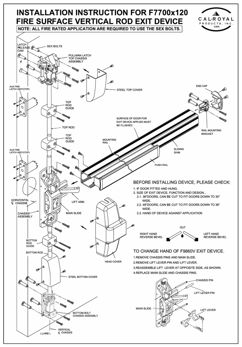
Cal-Royal F7700x120 User manual

Cal-Royal

Cal-Royal F7700x120 User manual

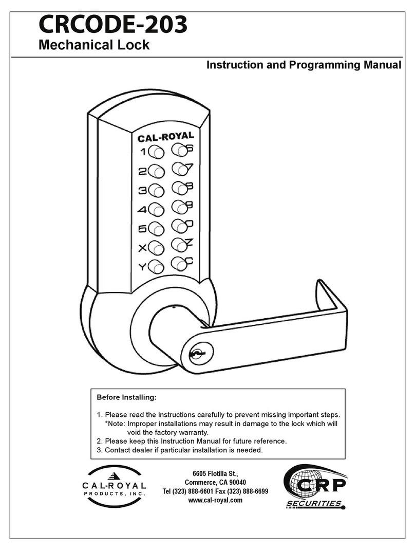
Cal-Royal CRCODE-203 Owner's manual

Cal-Royal

Cal-Royal CRCODE-203 Owner's manual

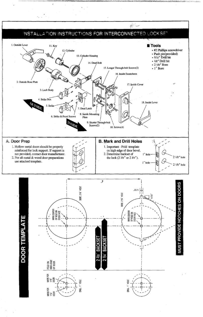
Cal-Royal HIL Series User manual

Cal-Royal

Cal-Royal HIL Series User manual

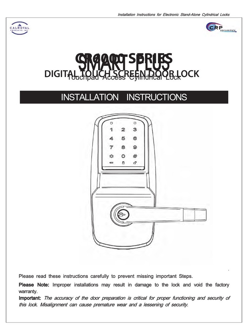
Cal-Royal CR6000 SERIES User manual

Cal-Royal

Cal-Royal CR6000 SERIES User manual

Popular Door Lock manuals by other brands

Design Hardware J Series instructions

Design Hardware

Design Hardware J Series instructions

Design Hardware F1000V LBR installation instructions

Design Hardware

Design Hardware F1000V LBR installation instructions

Orno OR-DB-KH-120 Operating and installation instructions

Orno

Orno OR-DB-KH-120 Operating and installation instructions

Schlage ND40 How to Install Button in Field

Schlage

Schlage ND40 How to Install Button in Field

Lock LAL4701 Installation instructions and template

Lock

Lock LAL4701 Installation instructions and template

Hans Grohe PuraVida Instructions for use/assembly instructions

Hans Grohe

Hans Grohe PuraVida Instructions for use/assembly instructions

SDC E75 Series Programming guide

SDC

SDC E75 Series Programming guide

Omron D41G manual

Omron

Omron D41G manual

JNF RC08M installation manual

JNF

JNF RC08M installation manual

ELFRI S2x05x Assembly instructions

ELFRI

ELFRI S2x05x Assembly instructions

FingerTec R3 user guide

FingerTec

FingerTec R3 user guide

Gainsborough Austral Lock Virtus Two Point Hinged Door Mortice... installation guide

Gainsborough

Gainsborough Austral Lock Virtus Two Point Hinged Door Mortice... installation guide

Stuv 3.31.2500.0 Assembly instructions

Stuv

Stuv 3.31.2500.0 Assembly instructions

Kaba E-Flash EF780 user guide

Kaba

Kaba E-Flash EF780 user guide

Alarm Lock DL6100 installation instructions

Alarm Lock

Alarm Lock DL6100 installation instructions

CodeLock CL500 instructions

CodeLock

CodeLock CL500 instructions

PDQ 5100 Series instruction sheet

PDQ

PDQ 5100 Series instruction sheet

Weiser Smartcode 10 installation guide

Weiser

Weiser Smartcode 10 installation guide

manuals.online logo
manuals.online logoBrands
  • About & Mission
  • Contact us
  • Privacy Policy
  • Terms and Conditions

Copyright 2025 Manuals.Online. All Rights Reserved.