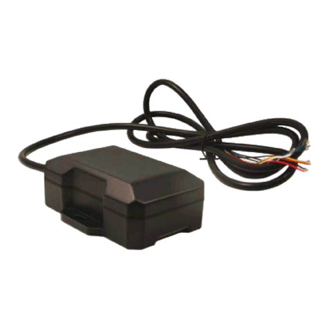
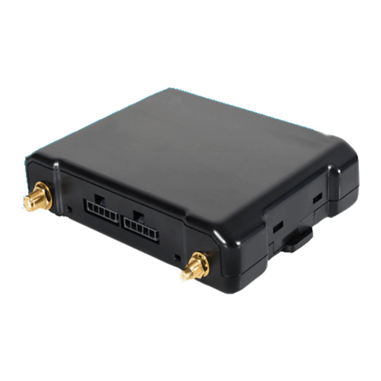
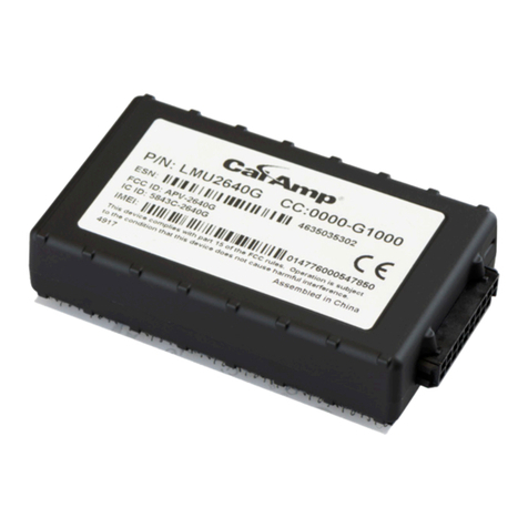
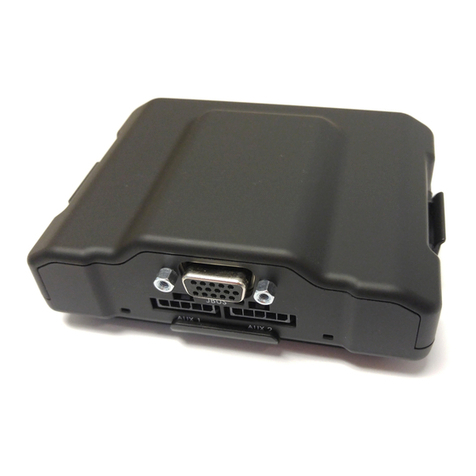
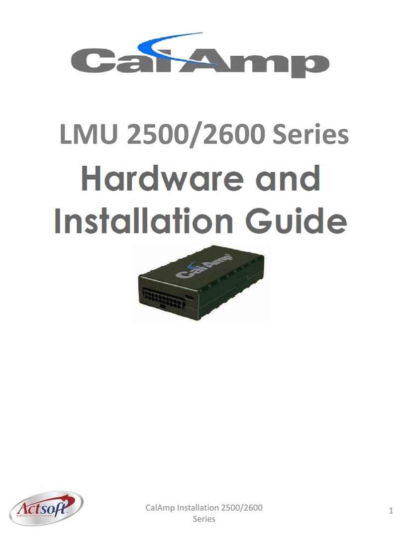
CalAmp LMU 2600 Series Manual

8/18/2021
LMU-2600 Hardware & Installation Guide - PULS Wiki
https://puls.calamp.com/wiki/LMU-2600_Hardware_%26_Installation_Guide
1/44
LMU-2600 Hardware & Installation Guide
LMU-2600™
Hardware and Installation Guide
IMPORTANT: DO NOT INSTALL OR USE THE SOFTWARE OR DOCUMENTATION UNTIL YOU
HAVE READ AND AGREED TO THE LICENSE AGREEMENT AND REVIEWED THE LIMITED
WARRANTY AND REGULATORY INFORMATION.
1 Introduction
Welcome to the LMU-2600™ Hardware and Installation Guide. This manual is intended to give you information on
the basic setup and installation of the CalAmp LMU-2600™ product(s) including hardware descriptions,
environmental specifications, wireless network overviews and device installation.
1.1 About This Manual
The LMU-2600™ is one of the most flexible economy mobile tracking hardware products available. In order
to accurately describe the functionality of these units we have broken this manual into the following sections:
System Overview – A basic description of a CalAmp LMU-2600™ based tracking system. This
includes a description of roles and responsibilities of each of the CalAmp components as well as a
brief overview of the wireless data technologies used by the LMU-2600™.
Hardware Overview – Describes the physical characteristics and interfaces of the LMU-2600™.
Installation and Verification – Provides guidance for the installation of the LMU-2600™ in a
vehicle and instructions on how to verify the installation is performing adequately.
1.2 About The Reader
In order to limit the size and scope of this manual, the following assumptions have been made about the
reader.
You are familiar with GPS concepts and terminology

8/18/2021
LMU-2600 Hardware & Installation Guide - PULS Wiki
https://puls.calamp.com/wiki/LMU-2600_Hardware_%26_Installation_Guide
2/44
You have some experience with installing equipment in vehicles
You are familiar with the use of AT Commands
You are familiar with the use of terminal programs such as HyperTerminal or PuTTY
1.3 About CalAmp
CalAmp is a leading provider of wireless communications products that enable anytime/anywhere access to
critical information, data and entertainment content. With comprehensive capabilities ranging from product
design and development through volume production, CalAmp delivers cost-effective high quality solutions to
a broad array of customers and end markets. The Company also provides wireless data communication
solutions for the telemetry and asset tracking markets, private wireless networks, public safety
communications and critical infrastructure and process control applications. For additional information, please
visit the Company’s website at www.calamp.com (http://www.calamp.com/) .
1.4 About the CalAmp Location Messaging Unit-LMU-2600™
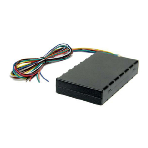
The CalAmp Location and Messaging Unit-LMU-2600™ (LMU-2600™) is a mobile device that resides in
private, commercial or government vehicles. The LMU-2600™ is a single box enclosure incorporating a
processor, a GPS receiver, a wireless data modem, and a vehicle-rated power supply. The LMU-2600™ also
supports inputs and outputs to monitor and react to the vehicular environment and/or driver actions.
Flexibility
The LMU-2600™ features CalAmp's industry leading advanced on-board alert engine that monitors vehicle
conditions giving you the most flexible tracking device in its class. The PEG™ (Programmable Event
Generator) application supports hundreds of customized exception-based rules to help meet customers'
dynamic requirements. Customers can modify the behavior of the device to meet with a range of applications
preprogrammed before shipment or in the field. Combining affordability and device intelligence with your
unique application can give you distinct advantages over your competition.
Over-the-Air Serviceability
The LMU-2600™ also incorporates CalAmp's industry leading over-the-air device management and
maintenance system software, PULS™ (Programming, Updates, and Logistics System). Configuration
parameters, PEG rules, and firmware can all be updated over the air. Our web-based maintenance server,
PULS™ scripts, and firmware, can all be updated over-the-air. PULS™ offers out-of-the-box hands free
configuration and automatic post-installation upgrades. You can also monitor unit health status across your
customers' fleets to quickly identify issues before they become expensive problems.
2 System Overview
2.1 Overview
The entire purpose behind a fleet management system is to be able to remotely contact a vehicle, determine its
location or status, and do something meaningful with that information. This could include displaying the
vehicle location on a map, performing an address look-up, providing real-time driving directions, updating the
vehicles ETA, monitoring vehicle and driver status or dispatching the vehicle to its next pick up.
These functions, of course, are completely dependent on the capabilities of the vehicle management
application. The role of the CalAmp LMU-2600™ is to deliver the location information when and where it is
8/18/2021
LMU-2600 Hardware & Installation Guide - PULS Wiki
https://puls.calamp.com/wiki/LMU-2600_Hardware_%26_Installation_Guide
3/44
needed.
A typical fleet management system based on a CalAmp device includes the following components:
A wireless data network
An LMU-2600™
Host Device (GPS NMEA only)
An LM Direct™ communications server
Backend mapping and reporting software which typically includes mapping and fleet reporting
functions
PULS™
LMU Manager™
Basic System Architecture
2.2 Component Descriptions
2.2.1 Wireless Data Network
The Wireless Data Network provides the information bridge between the LM Direct™ server and the LMU-
2600™. Wireless data networks can take a variety of forms, such as cellular networks, satellite systems or
local area networks. Contact the CalAmp sales team for the networks available to the LMU-2600™.

8/18/2021
LMU-2600 Hardware & Installation Guide - PULS Wiki
https://puls.calamp.com/wiki/LMU-2600_Hardware_%26_Installation_Guide
4/44
2.2.2 LMU-2600™
The LMU-2600™ is responsible for delivering the location and status information when and where it is
needed. Data requests mainly come from the following sources:
PEG™ script within the LMU-2600™
A location or status request from the LM Direct™ server
A location or status request from LMU Manager
An SMS request made from a mobile device such as a customer’s cell-phone
In some cases, it is necessary to run an application in the vehicle while it is being tracked by the backend
software. Such examples could include instant messaging between vehicles or a central office, in-vehicle
mapping or driving directions, email or database access. In most of these cases you will be using the LMU-
2600™ as a wireless modem as well as a vehicle-location device.
2.2.3 LM Direct™ Server
LM Direct™ is a CalAmp proprietary message interface specification detailing the various messages and their
contents the LMU-2600™ is capable of sending and receiving. This interface allows System Integrators to
communicate directly with LMU-2600's™. Please refer to the LM Direct Reference Guide for details.
2.2.4 Backend Software
Backend software is a customer provided software application. Regardless of its purpose, one of its primary
functions is to parse and present data obtained from the LM Direct™ server. This allows the application to do
any of the following:
Display location database on reports received from the LMU-2600™ in a variety of formats
Present historic information received from the LMU-2600™, typically in a report/chart style
format
Request location updates from one or more LMU-2600s™
Update and change the configuration of one or more LMU-2600s™
2.2.5 PULS™
PULS™ (Programming, Update and Logistics System) is CalAmp’s web-based maintenance server offering
out-of-the-box hands free configuration and automatic post-installation upgrades. PULS™ provides a means
for configuration parameters, PEG scripts, and firmware to be updated Over-The-Air (OTA) and allows
CalAmp customers to monitor unit health status across your customers’ fleets to quickly identify issues before
they become expensive problems.
2.2.6 LMU Manager™

8/18/2021
LMU-2600 Hardware & Installation Guide - PULS Wiki
https://puls.calamp.com/wiki/LMU-2600_Hardware_%26_Installation_Guide
5/44
LMU Manager is the primary configuration tool in the CalAmp system. It allows access to almost every
feature available to the LMU-2600™. Unlike the backend software, it has the option of talking directly to an
LMU-2600™ or making a request forwarded by the LM Direct™ server.
For further details on using LMU Manager, please refer to the LMU Manager Users Guide.
3 Hardware Overview
3.1 Location Messaging Unit-LMU-2600™
3.1.1 LMU-2600™ Handling Precautions
Electrostatic Discharge (ESD)
Electrostatic discharge (ESD) is the sudden and momentary electric current that flows between two objects at
different electrical potentials caused by direct contact or induced by an electrostatic field. The term is usually
used in the electronics and other industries to describe momentary unwanted currents that may cause damage
to electronic equipment.
ESD Handling Precautions
ESD prevention is based on establishing an Electrostatic Protective Area (EPA). The EPA can be a small
working station or a large manufacturing area. The main principle of an EPA is that there are no highly
charging materials in the vicinity of ESD sensitive electronics, all conductive materials are grounded, workers
are grounded, and charge build-up on ESD sensitive electronics is prevented. International standards are used
to define typical EPA and can be obtained for example from International Electro-technical Commission (IEC)
or American National Standards Institute (ANSI).
This ESD classification of the sub assembly will be defined for the most sensitive component, therefore the
following classifications apply:
Class 1B – Human Model (< 1 kV)
Class M1 – Machine Model (< 100V)
When handling the LMU-2600’s™ main-board (i.e. sub assembly) by itself or in a partial housing proper ESD
precautions should be taken. The handler should be in an ESD safe area and be properly grounded.
WARNING: This product can expose you to chemicals including carbon black, nickel, & bisphenol A,
which are known to the State of California to cause cancer and birth defects or other reproductive harm. For
more information go to https://www.P65Warnings.ca.gov.
GPS Ceramic Patch Handling
When handling the sub assembly it may be natural to pick it up by sides and make contact with the antenna
boards. In an uncontrolled ESD environment contact with the center pin of ceramic patch antenna can create a
path for electrostatic discharge directly to the GPS Module. The GPS Module is very sensitive to ESD and can
be damaged and rendered non-functional at low levels of ESD.
One should avoid contact with the center pin of the patch during handling.

8/18/2021
LMU-2600 Hardware & Installation Guide - PULS Wiki
https://puls.calamp.com/wiki/LMU-2600_Hardware_%26_Installation_Guide
6/44
Packaging
Anytime the sub assembly is shipped and it is not fully packaged in its final housing it must be sealed in an

ESD safe bag.
Electrical Over-Stress (EOS)
The GPS receiver can be damaged if exposed to an RF level that exceeds its maximum input rating. Such
exposure can happen if a nearby source transmits an RF signal at sufficiently high level to cause damage.
Storage and Shipping
One potential source of EOS is proximity of one LMU-2600™ GPS Antenna to another LMU-2600™ GSM
Antenna. Should one of the units be in a transmit mode the potential exists for the other unit to become
damaged. Therefore any LMU-2600™ GPS Antenna should be kept at least four inches apart from any active
LMU-2600™ GSM Antenna or any other active high power RF transmitter with power greater than 1 Watt.
3.1.2 Battery Back-up devices
Please properly dispose of the battery in any of the CalAmp products that utilize one, do not just throw used
batteries, replaced batteries, or units containing a back-up battery into the trash. Consult your local waste
management facility for proper disposal instructions.
3.1.3 Environmental Specifications
The LMU-2600™ is designed to operate in environments typically encountered by fleet vehicles, including
wide temperature extremes, voltage transients, and potential interference from other vehicle equipment.
To ensure proper operation in such an environment, the LMU-2600™ was subjected to standard tests defined
by the Society of Automotive Engineers (SAE). The specific tests included temperature, shock, vibration, and
EMI/EMC. These tests were performed by independent labs and documented in a detailed test report. In
accordance with Appendix A of SAE J1113 Part 1, the Unit is considered a “Functional Status Class B,
Performance Region II” system that requires Threat Level 3 Testing.
The following shows the environmental conditions the LMU is designed to operate in and the relevant SAE
tests that were performed. No formal altitude tests were conducted.
Dimensions
3.972”(L) x 1.953”(W) x 0.917”(H)
100.88mm (L) x 49.606mm (W) x 23.291mm (H)
Weight
1.6oz (45.359g)
Operating Temperature
-30o C to 75o C

8/18/2021
LMU-2600 Hardware & Installation Guide - PULS Wiki
https://puls.calamp.com/wiki/LMU-2600_Hardware_%26_Installation_Guide
7/44
Storage Temperature
-40o C to 85o C
Humidity
0% to 95% relative humidity, non-condensing
Shock and Vibration
SAE Test: SAE J1455 Compliant
Mil Standard 202G and 810F Compliant
Ground vehicle environment with associated shock and vibration
Electromagnetic Compatibility (EMC/EMI)
SAE Test: SAE J1113 Parts 2, 12, 21 and 41 Compliant
FCC Part 15B Compliant
Industry Canada Compliant
EMC compliant for a ground vehicle environment
Operating Voltage Range
7 – 32VDC
Power Consumption
Active Standby :70mA at 12VDC
Sleep on Network (SMS): 10mA
Sleep on Network (GPRS): 20mA
Deep Sleep: 3mA
GPS
50 channel (with SBAS, DGPS) GPS Receiver
2m CEP (with SA off)
-160 dBm tracking sensitivity
Communications (Comm)
Quad Band Class 12 GPRS Modem
850 MHz (Class 4) – 2W
900 MHz (Class 4) – 2W
1800 MHz (Class 1) – 1W
1900 MHz (Class 1) -1 W
GPRS Packet Data (UDP)
SMS
RoHS Compliant
3.2 Primary Connector

8/18/2021
LMU-2600 Hardware & Installation Guide - PULS Wiki
https://puls.calamp.com/wiki/LMU-2600_Hardware_%26_Installation_Guide
8/44
The LMU-2600™ uses a Male (pin) Molex Micro-Fit 3.0TM Dual Row, 20 circuit header to receive power,
ground and supply input and output signals. The pin out is as follows:
Wire Signal
Name Description Color Input or
Output
1 GND Ground Black (22
AWG) Ground
2 OUT-0 Output 0 –Started Disable Relay
Driver
Green (22
AWG) Output
3 IN-1 Input 1 – Digital Input Blue (22
AWG) Input
4 TXD Host TxD Blue (22
AWG) Input
5 ADC-1 Analog to Digital Input 1 Pink (22
AWG) Input
6 IN-3 RESERVED Violet (22
AWG)
7 OUT-3/(IN-4) RESERVED Grey (22
AWG)
8 IN-0 Ignition White (20
AWG) Input
9VDD VDD Reference Output (20-25mA
Max)
Orange (22
AWG) Output
10 OUT-1 Output 1 – Digital Output (Open
Collector)
Brown (22
AWG) Input
11 OUT-2 Output – 2 Digital Output (Open
Collector)
Yellow (22
AWG) Output
12 IN-2 Input 2 – Digital Input Orange (22
AWG) Input
13 RxD Host RxD Green (22
AWG) Output
14 VCC Primary Power Input Red (20 AWG) Power
15 GND Primary Ground Black (20
AWG) Ground
16 1BB-GND 1 Bit Bus Ground Black (22
AWG) Ground
17 1BB-D 1-Bit Bus Data White/Blue Input/Output
18 Aux - TxD Aux Port - Transmit Data White/Orange Input
19 Aux - GND Aux Port - Ground Black Ground
20 Aux - RxD Aux Port - Receive Data White/Yellow Output

8/18/2021
LMU-2600 Hardware & Installation Guide - PULS Wiki
https://puls.calamp.com/wiki/LMU-2600_Hardware_%26_Installation_Guide
9/44
LMU-2600™ Header
The mating connector for the LMU-2600™ is the 3.00mm (.118") Pitch Micro-Fit 3.0™ Receptacle Housing,
Dual Row, 20 Circuits connector. Part Number 430252000
(www.molex.com (http://www.molex.com/pdm_docs/ps/PS-43045.pdf) )
3.2.1 LMU-2600™ - 3 Wire Power Cable
The standard power harness for the LMU-2600™ comes in two varieties:
Part Number 5C849-8: 20-pin basic 3-Wire Power Harness (unfused)
Part Number 5C848-8: 20 pin basic w-Wire Power Harness (fused)
Basic 3-Wire Power Harness - unfused
Basic 3-Wire Power Harness - fused

8/18/2021
LMU-2600 Hardware & Installation Guide - PULS Wiki
https://puls.calamp.com/wiki/LMU-2600_Hardware_%26_Installation_Guide
10/44
3.2.2 LMU-2600™ – Full I/0 Wiring Harness – Part Number 5C867
This harness provides the complete set of I/O connectors including fused Power and Ignition lines.
Full I/O Wiring Harness
3.2.3 LMU-2600™ - Serial Adapter
To add a host serial adapter to the LMU-2600™ there are 2 additional parts:
Part Number 133360: Serial Pigtail Adapter. This is connected to 5C867 to provide a connection
for the Serial Adapter itself
Part Number 133337: Serial Adapter.
LMU-2600™ Serial Pigtail Adapter
LMU-2600™ Serial Adapter

8/18/2021
LMU-2600 Hardware & Installation Guide - PULS Wiki
https://puls.calamp.com/wiki/LMU-2600_Hardware_%26_Installation_Guide
11/44
Attaching the Pig-Tail Serial Adapter
These instructions describe how to connect the Serial Pig-Tail Adapter to the LMU-2600™’s 20 Pin wiring
harness. It is recommended that the LMU be powered-off and the cable detached when installing the lead kit.
Insert crimped pins, one at a time into the back of the 20-pin wiring harness connector as indicated in the steps
below.
1. Install Black ground lead to pin 1 of 20-pin connector on wiring
2. Install Blue TXD lead to pin 4 of 20-pin connector on wiring harness.(if pin 1 is occupied, alternate locations
are pin 16, and pin 19)
3. Install Green RXD lead to pin 13 of 20-pin connector on wiring harness
4. Install Orange VDD lead to pin 9 of 20-pin connector on wiring harness
Back view of 20-pin connector
3.2.4 LMU-2600™ Miscellaneous Accessories
The following items are available from CalAmp for use with the LMU-2600™’
Part Number 4C763: iButton Reader and Cable Assembly
Part Number 4C764: Switch LED Cable Assembly
Part Number 4C765: Buzzer and Cable Assembly
iButton Reader and Cable Assembly

8/18/2021
LMU-2600 Hardware & Installation Guide - PULS Wiki
https://puls.calamp.com/wiki/LMU-2600_Hardware_%26_Installation_Guide
12/44
Switch LED Cable Assumbly
Buzzer and Cable Assembly
3.2.5 GPS Receiver
The LMU-2600™’s GPS receiver has the following specifications:
50 channel GPS receiver
Accuracy: 2 meter CEP (with SA off)
-160dBm Tracking Sensitivity
For external models, the antenna connector is SMA female.

8/18/2021
LMU-2600 Hardware & Installation Guide - PULS Wiki
https://puls.calamp.com/wiki/LMU-2600_Hardware_%26_Installation_Guide
13/44
Note that the CalAmp LMU-2600™ requires an antenna amplifier that operates at 3VDC; 5VDC amps will
not work.
3.3 External RF Connector
The external antenna connection for the LMU-2600™ is SMC with a 50 Ω nominal impedance.
3.4 I/O Descriptions
The LMU-2600™ provides the following I/O:
Digital Inputs
Input 0: Ignition Sense (Always biased low)
Input 1: Generic Digital Input (always biased low)
Input 2: Generic Digital Input (always biased high)
Input 3: Generic Digital Input (always biased high
Input 4: Generic Digital Input (always biased high
Input 5: Motion Sensor (low = no motion, high = motion)
Analog to Digital Inputs
A/D 0: External Power Supply Monitor
A/D 1: Generic External A/D Input
A/D 2: GPS Antenna Monitor
Outputs:
Output 0: Standard Open Collector Relay Output (150mA)
Output 1: Standard Open Collector Relay Output (150mA)
Output 2: Standard Open Collector Relay Output (150mA)
1-Wire® Interface
Temperature Sensor Support
iButton ID Support (based on S-171 settings)
3.4.1 3-Axis Accelerometer Input
The LMU-2600™ supports an internal 3 Axis Precision Accelerometer as one of its discreet inputs. When the
LMU is moved in any direction, the associated input will be in the High state. If the LMU’s accelerometer
does not detect motion, then the input will be in the Low state. No external connections are required for this
functionality to be operational.
3.4.2 Ignition and Inputs
The LMU-2600™ provides up to 5 external inputs and one internal. The external inputs are protected from
typical vehicle transients and can be directly connected to most vehicle level logical inputs from 4 volts up to

8/18/2021
LMU-2600 Hardware & Installation Guide - PULS Wiki
https://puls.calamp.com/wiki/LMU-2600_Hardware_%26_Installation_Guide
14/44
the vehicle power input level (typically 12 VDC). Their input impedance is approximately 10k. One of these
inputs is dedicated to sensing the vehicle’s ignition status to provide for flexible power management. The
other two inputs may be used to sense vehicle inputs such as cooling unit operation, a hidden driver “Panic”
switch, taxi on-duty/off-duty meter status or many others.
The ignition input is pulled to ground through the 10k resistance, where the other inputs can either be
normally High (i.e. pulled to +12v through a 10k resistor) or Low (i.e. pulled to ground through a 10k
resistor). Input 1 is always biased low, inputs, 2-4 are biased high The diagrams below show how to connect
the inputs in both a high- and low-biased configuration:

8/18/2021
LMU-2600 Hardware & Installation Guide - PULS Wiki
https://puls.calamp.com/wiki/LMU-2600_Hardware_%26_Installation_Guide
16/44
The LMU’s outputs are designed to drive external relays. These outputs provide a high-current, open-collector
driver that can sink up to 150 mA each. These drivers may be used to drive external relays that can then
control vehicle functions such as door locks, fuel shut-off valves, sirens and lights. If additional current is
required to drive the relays, external circuitry can be added to source the current. This diagram is a typical use
of an output to drive a relay.
Sample Relay Wiring
3.4.4 Status LEDs
The LMU-2600™ is equipped with two Status LEDs, one for GPS and one for COMM (wireless network
status). The LEDs use the following blink patterns to indicate service:
LED #1 (Comm LED - Orange) Definitions
Condition LED 1
Modem Off Off
Comm On - Searching Slow Blinking
Network Available Fast Blinking
Registered but no Inbound Acknowledgement Alternates from Solid to Fast Blink every 1s
Registered and Received Inbound Acknowledgement Solid
LED #2 (GPS LED - Yellow) Definitions
Condition LED 1
GPS Off Off
GPS On Slow Blinking
GPS Time Sync Fast Blinking
GPS Fix Solid

8/18/2021
LMU-2600 Hardware & Installation Guide - PULS Wiki
https://puls.calamp.com/wiki/LMU-2600_Hardware_%26_Installation_Guide
17/44
LMU-2600™ LED Positions
4 Configuration and Activation
This section details how to quickly get an LMU-2600™ provisioned and configured to point at a specific server. It is
assumed that a PEG script has already been created and is being managed through LMU Manager or PULS™, the
CalAmp Maintenance System.
We are making three assumptions to simplify the setup process:
You have created, installed and configured an LM Direct™ Server to receive messages from the LMU-
2600™. (See LM Direct™ Reference Guide for details)
You are using the standard wiring harness from CalAmp and the serial port expansion harness.
You have created a HyperTerminal or Putty session.
You have contacted the CalAmp sales team regarding the network availability of the LMU-
2600™. This device may not be supported for all the carriers or networks listed in this section (CDMA-
Verizon, CDMA-Sprint, HSPA, GSM), for product availability consult the CalAmp sales team.
4.1 Quick Start - General Config
All LMU-2600s™ must go through a common step during the configuration and provisioning process.
Specifically, this is pointing the LMU to your LM Direct™ server, either via IP or a URL.
This configuration process is accomplished via a series of AT Commands:
1. Power up the LMU-2600™ and connect a serial cable from the LMU to your laptop
2. Open a terminal session to the LMU-2600™
3. Enter the address of the LM Direct™ server:
AT$APP PARAM 2319,0,ddd.ddd.ddd.ddd
AT$APP PARAM 768,0,ddd.ddd.ddd.ddd (32-bit products only)
AT$APP PARAM 769,0,ppppp

8/18/2021
LMU-2600 Hardware & Installation Guide - PULS Wiki
https://puls.calamp.com/wiki/LMU-2600_Hardware_%26_Installation_Guide
18/44
Where ddd.ddd.ddd.ddd is the publicly addressable IPV4 address of your LM Direct™ server and
ppppp is the UDP port number.
4. Alternatively if a URL has been set up for your LM Direct™ server, the LMU may be programmed
with:
AT$APP PARAM 2319,0,myURL.MyCompany.Com
Where myURL.MyCompany.com is the URL assigned to the server.
5. Enter ATIC to verify the correct settings are displayed for your Inbound Server.
This configuration process is accomplished via a series of SMS Commands:
1. Power up the LMU-2600™ and your handset
2. From the handset, send an SMS message to the LMU-2600™ phone number:
!RP,2319,0,ddd.ddd.ddd.ddd
!RP,768,0,ddd.ddd.ddd.ddd (32-bit products only)
!RP,769,0,ppppp
Where ddd.ddd.ddd.ddd is the publicly addressable IPV4 address of your LM Direct™ server and
ppppp is the UDP port number
3. Alternatively if a URL has been set up for your LM Direct™ server, the LMU may be programmed
with:
!RP,2319,0,myURL.MyCompany.Com
Where myURL.MyCompany.com is the URL assigned to the server
4. Verify your settings by sending the commands:
!RP?2319,0
!RP?769,0
4.2 Auto provisioning of GSM or HSPA LMUs
For certain operators, the LMU can auto-populate the APN, username and password settings based on the
Mobile Country Code (MCC) and the Mobile Network Code (MNC) of the SIM. Upon inserting a new SIM
the APN, username and password will switch to the new SIM card's defaults if the MCC and MNC values
change. The current list of supported MCC and MNC combinations are:
AT&T – formerly AT&T Wireless or Cingular Blue (MCC 310, MNC 38)

8/18/2021
LMU-2600 Hardware & Installation Guide - PULS Wiki
https://puls.calamp.com/wiki/LMU-2600_Hardware_%26_Installation_Guide
19/44
o APN 0: PROXY
o APN 1: PUBLIC
AT&T – formerly Cingular Wireless (MCC 310, MNC 17, 18, 41)
o APN 0 & 1: ISP.CINGULAR
o Username: [email protected]
o Password: CINGULAR1
Manxpronto (MCC 234, MCN 058)
o APN web.manxpronto.net
o Username: gprs
o Password: gprs
O2 UK (MCC 234, MNC 02, 10, 11)
o APN 0 & 1: mobile.o2.co.uk
o Username: mobileweb
o Password: password
O2 Ireland (MCC 272, MNC 02)
o APN 0 & 1: open.internet
o Username: gprs
o Password: gprs
Orange UK (MCC 234, MNC 33, 34)
o APN 0 & 1: orangeinternet
o Username: user
o Password: pass
T-Mobile (MCC 310, MNC 16, 20, 21, 22, 23, 24, 25, 26, 27, 31, 58, 66, 80)
o APN 0: INTERNET2.VOICESTREAM.COM
o APN 1: INTERNET3.VOICESTREAM.COM
T-Mobile UK (MCC 234, MNC 30,31,32)
o APN 0 & 1: general.t-mobile.uk
o Username: user
o Password: wap
TelCel Mexico (MCC 334 MNC 02)
o APN 0 & 1: INTERNET.ITELCEL.COM
o Username: webgprs
o Password: webgprs2002
Telstra Australia (MCC 505, MNC 01, 11, 71, 72)
o APN 0 & 1: telstra.internet
Vodafone Ireland (MCC 272, MNC 01)
o APN 0 & 1: isp.vodafone.ie

8/18/2021
LMU-2600 Hardware & Installation Guide - PULS Wiki
https://puls.calamp.com/wiki/LMU-2600_Hardware_%26_Installation_Guide
20/44
o Username: vodafone
o Password: vodafone
Vodafone New Zealand (MCC 530, MNC 01)
o APN 0 & 1: internet
o Username: guest
o Password: guest
Vodafone UK (MCC 234, MNC 15)
o APN 0 & 1: internet
o Username: web
o Password: web
Unless otherwise stated, the username and password will be set to “dummy”.
This feature can be disabled by setting Bit 0 of S-Register 155.
AT$APP PARAM 1024,35,1,1
To re-enable auto-provisioning, use:
AT$APP PARAM 1024,35,1,0
Auto-provisioning occurs when the LMU detects a SIM with a new operator ID (i.e. the first 6 digits of the
IMSI) or when Bit 0 of S155 is cleared and the GPRS context is blank (i.e. Parameter 2306,0).
4.3 Activating GSM or HSPA LMU using AT Commands
Check with the CalAmp Sales team for availability of the LMU-2600™ with GSM or HSPA modems.
For a GSM/GPRS operator you will get the LMU in one of two varieties, one with a SIM and one without.
If you get an LMU without a SIM (which is the typical case) the operator will simply ask for the IMEI of the
LMU. The IMEI (International Mobile Equipment Identifier) is printed on the bottom of the LMU under the
LMU’s ESN. Again, DO NOT give the operator the ESN of the LMU.
The operator will provide you with a SIM for each account activated. If they are especially nice (or you are
especially persistent) they will also give you a list tying the IMSI (International Subscriber Identifier) of the
SIM to the phone number assigned to it. Please note that the operator will likely tie the IMSI (i.e. the SIM) to
a specific IMEI. Making sure the specific SIM matches to the right IMEI isn’t strictly necessary, but it will
keep everyone’s book-keeping a little cleaner. You may also obtain this information by running a CSV report
in PULS (after the devices have connected to the network and sent in their first ID Report). See the PULS
Users Guide for more information.
If you do happen to have a SIM, the operator will ask for the IMSI and ICC-ID (Integrated Circuit Card
Identifier) along with the IMEI of the LMU. Again, in return you should get a list of IMSIs and Phone
Numbers.
Table of contents
Other CalAmp GPS manuals

CalAmp
CalAmp LMU-5000 Manual

CalAmp
CalAmp LMU-2x30 User manual

CalAmp
CalAmp TTU-2830 Manual

CalAmp
CalAmp TTU-7 Series User manual

CalAmp
CalAmp LMU-3030 User manual

CalAmp
CalAmp LMU-2000 Manual

CalAmp
CalAmp LMU 26 User manual

CalAmp
CalAmp LMU-3050 User manual

CalAmp
CalAmp Safe Fleet LMU 2630 LV User manual

CalAmp
CalAmp CVF-200-23 Datasheet

CalAmp
CalAmp HMU-3640 Manual

CalAmp
CalAmp LMU-5541 Manual

CalAmp
CalAmp SC1205V User manual

CalAmp
CalAmp LMU-2 30 Series User manual

CalAmp
CalAmp TTU-4531 User manual

CalAmp
CalAmp SC1302 Operator's manual

CalAmp
CalAmp LMU-3 Series Manual

CalAmp
CalAmp LMU-1300 Setup guide

CalAmp
CalAmp LMU-4200 User manual

CalAmp
CalAmp LMU-3000 Manual