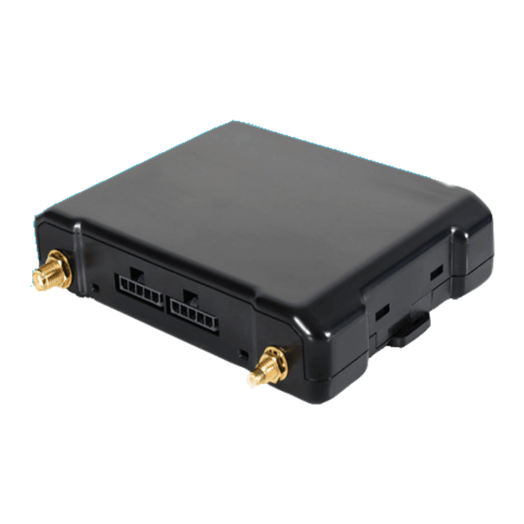
CalAmp TTU-7 Series User manual

CalAmp Corp.
13645 Dulles Technology Drive, Herndon, VA 20171 Document: MBUD-0239v3
Phone: 703. 262.0500 Jan 2017
Fax: 703.262.0380
www.calamp.com
TTU-7xxTM Install Guide

CalAmp | TTU-7xx Install Guide
Page ii MBUD-0239v2
CalAmp | TTU-7xxTM Install Guide
Copyright © 2017 CalAmp Corporation. All rights reserved.
Printed in the United States of America.
All trademarks used are properties of their respective owners.
Products offered may contain software proprietary to CalAmp or other parties. The offer of supply of
these products and services does not include or infer any transfer of ownership. No part of the
documentation or information supplied may be divulged to any third party without the express written
consent of CalAmp.
CalAmp reserves the right to modify the equipment, its specification or this manual without prior notice,
in the interest of improving performance, reliability, or servicing. At the time of publication all data is
correct for the operation of the equipment at the voltage and/or temperature referenced. Performance
data indicates typical values related to the particular product.
Product updates may result in differences between the information provided in this manual and the
product shipped. We have made every effort to ensure the accuracy of all information contained in this
document; however, CalAmp makes no expressed or implied warranty or representation based upon the
enclosed information.
Revision History:
Version #
Revision Date
Author
Details
1.0
12/5/2012
Product
Baseline release
2.0
01/30/2014
Product
Revised to CalAmp
3.0
02/14/2017
Product
Added magnetic mount installation

CalAmp | TTU-7xx Install Guide
MBUD-0239v2 Page iii
TABLE OF CONTENTS
1REGULATORY INFORMATION .......................................................................................... 1
1.1 HUMAN EXPOSURE COMPLIANCE STATEMENT ......................................................................................... 1
1.2 HARDWARE PRECAUTIONS.................................................................................................................... 1
2SAFETY INFORMATION .................................................................................................... 2
2.1 SECURE/STABILIZE EQUIPMENT ............................................................................................................. 2
2.2 WORKING ON ELEVATED SURFACES........................................................................................................ 2
2.3 HANDLING LITHIUM BATTERIES ............................................................................................................. 2
3INTRODUCTION............................................................................................................... 4
4TTU-7XX OVERVIEW ........................................................................................................ 5
4.1 ENVIRONMENTAL SPECIFICATIONS ......................................................................................................... 6
5TTU-7XX INSTALLATION CONSIDERATIONS ...................................................................... 7
5.1 PLAN THE INSTALLATION ...................................................................................................................... 7
5.2 ACTIVATION MAGNET.......................................................................................................................... 7
6DRY VAN AND REEFER NOSE MOUNT INSTALLATION ....................................................... 8
7CHASSIS MAGENTIC MOUNT INSTALLATION .................................................................. 11
8INTERMODAL CONTAINER DOOR SCREW MOUNT INSTALLATION .................................. 15
9FLATBED SCREW MOUNT INSTALLATION ....................................................................... 19
10 BATTERY REPLACEMENT PROCEDURE......................................................................... 21
11 DE-INSTALLATION INSTRUCTIONS............................................................................... 24
12 WARRANTY................................................................................................................ 25
13 CUSTOMER SUPPORT CONTACT INFORMATION.......................................................... 26

CalAmp | TTU-7xx Install Guide
Page iv MBUD-0239v2
LIST OF FIGURES
Figure 1: TTU-7xx .......................................................................................................................................... 5
Figure 2: TTU-7xx Device Label ..................................................................................................................... 9
Figure 3: Nose Mount ................................................................................................................................... 9
Figure 4: TTU-7xx Device Label ................................................................................................................... 16
Figure 5: Top Left Container Door –Device Mounted in Corrugation Well Between Locking Rods .......... 17
Figure 6: Sealant Applied to Backside.........................................................................................................17
Figure 7: Final Installation with Label Facing Down.................................................................................... 18
Figure 8: TTU-7xx Device Label ................................................................................................................... 19
Figure 9: Flatbed Nose Rail Device Mount –Mount Device Where It Will Not Be Damaged..................... 20
Figure 10: Remove Battery Cap ..................................................................................................................21
Figure 11: Disconnect the Battery Connector............................................................................................. 22
Figure 12: Power Disconnected ..................................................................................................................22
Figure 13: Proper Alignment to Slide Battery Out and In of Enclosure ......................................................23
Figure 14: Reconnect Power Cables............................................................................................................ 23

CalAmp | TTU-7xx Install Guide
Page 1 MBUD-0239v2
1 REGULATORY INFORMATION
1.1 Human Exposure Compliance Statement
Pursuant to 47 CFR § 24.52 of the FCC Rules and Regulations, personal communications services (PCS)
equipment is subject to the radio frequency radiation exposure requirements specified in § 1.1307(b), §
2.1091 and § 2.1093, as appropriate.
CalAmp and its supplier certify that it has determined that the TTU-7xx complies with the RF hazard
requirements applicable to broadband PCS equipment operating under the authority of 47 CFR Part 24,
Subpart E of the FCC Rules and Regulations. This determination is dependent upon installation,
operation and use of the equipment in accordance with all instructions provided.
The TTU-7xx is designed for and intended to be used in fixed and mobile applications. “Fixed” means
that the device is physically secured at one location and is not able to be easily moved to another
location. “Mobile” means that the device is designed to be used in other than fixed locations and
generally in such a way that a separation distance of at least 20 cm is normally maintained between the
transmitter’s antenna and the body of the user or nearby persons. The TTU-7xx is not designed for or
intended to be used in portable applications (within 20 cm of the body of the user) and such uses are
strictly prohibited.
To ensure that the TTU-7xx complies with current FCC regulations limiting both maximum RF output
power and human exposure to radio frequency radiation, a separation distance of at least 20 cm must
be maintained between the unit’s antenna and the body of the user and any nearby persons at all times
and in all applications and uses. Additionally, in mobile applications, maximum antenna gain must not
exceed 3 dBi.
1.2 Hardware Precautions
Electrical Over-Stress (EOS)
The TTU-7xx GPS receiver can be damaged if exposed to an RF level that exceeds its maximum input
rating. Such exposure can happen if a nearby source transmits an RF signal at sufficiently high level to
cause damage.
Storage and Shipping
One potential source of EOS is proximity of one TTU-7xx device to another TTU-7xx device. Should one
of the units be in a transmit mode, the potential exists for the other unit to become damaged.
Therefore, any TTU-7xx should be kept at least four inches apart from any active TTU-7xx or any other
active high power RF transmitter with power greater than 1 Watt.

CalAmp | TTU-7xx Install Guide
Page 2 MBUD-0239v2
2 SAFETY INFORMATION
The Safety Information section contains safety information related to the CalAmp TTU-7xx device and
installation.
2.1 Secure/Stabilize Equipment
Installers should follow OSHA regulatory requirements for working on equipment, or parts thereof,
which are suspended or held aloft by use of slings, hoists or jacks.
Whenever the equipment is parked, set the parking brake. For equipment parked on inclines, chock the
wheels and set the parking brake.
Equipment, or parts thereof, which are suspended or held aloft by use of slings, hoists, or jacks should
be substantially blocked or cribbed to prevent falling or shifting working under or between them.
2.2 Working on Elevated Surfaces
Installers should follow OSHA regulatory requirements for working on elevated surfaces. When installers
are on the tops or roofs of equipment, they should employ a fall protection system consistent with OSHA
regulations.
2.3 Handling Lithium Batteries
The CalAmp TTU-7xx uses a lithium battery.
Storage
CalAmp TTU-7xx batteries not installed within a 4-week period from the time of delivery must be stored
in a cool, dry place. Store in a cool (below 30° C (86° F)), dry and ventilated area, which is subject to little
temperature change. Do not place the battery near heating equipment, nor expose to direct sunlight for
long periods. Elevated temperatures can result in shortened battery life and degrade performance.
CAUTION: Failure to properly store batteries will void the warranty.
Disposal/Recycling Batteries
All lithium batteries whether recycled or disposed must be done in accordance with applicable local,
State and Federal regulations.
NOTE: Battery must be removed from the TTU-7xx before return shipment.

CalAmp | TTU-7xx Install Guide
MBUD-0239v2 Page 3
Waste Management
Any solid or hazardous waste or refuse generated as a result of the installation process shall be
managed, stored, transported, and disposed of in accordance with any and all applicable federal, state,
and local regulations. In addition, verify all processes or procedures used to handle, store, transport and
dispose of any generated waste.
The following waste may be generated after an installation:
Cloths or Paper Towels
Cloths or Paper Towels with Adhesive or Degreaser
Empty Adhesive and Degreaser Containers
Batteries
Cardboard
Metal Shavings
General Waste or Garbage

CalAmp | TTU-7xx Install Guide
Page 4 MBUD-0239v2
3 INTRODUCTION
This manual provides information on the basic setup and installation of the TTU-7xx device including
hardware descriptions, environmental specifications and device installation.
Before installing any TTU-7xx components, you must:
Read this document thoroughly
Collect all required materials and tools
This guide provides qualified technicians the steps required to install the TTU-7xx device. The device
collects critical asset location and operational data and transmits that data to the CalAmp FleetOutlook
application, where end-users can review the data through the application interface and generated
reports.
This document provides the installation steps for the following asset configurations:
Dry Van and Reefer Nose Mount Installation
Intermodal Container Door Screw Mount Installation
Flatbed Screw Mount Installation
Battery Replacement Procedures

CalAmp | TTU-7xx Install Guide
MBUD-0239v2 Page 5
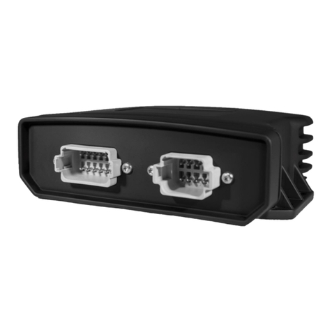
4 TTU-7xx OVERVIEW
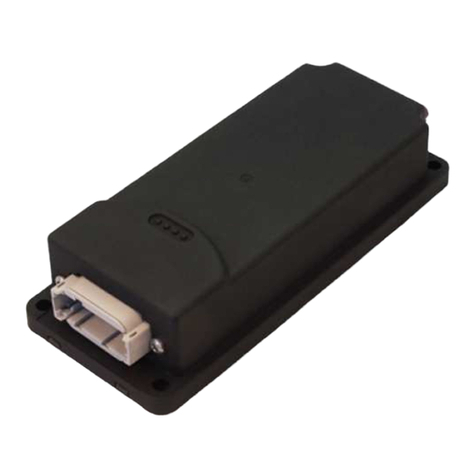
The TTU-7xx is a battery-operated product with a field-replaceable battery designed for multi-year
deployments. It features a small size, superior GPS performance and an internal 57 Ah battery. The TTU-
7xx is a complete asset tracking and communication device incorporating next-generation, super-
sensitive GPS technology for installation in any mobile asset. Superior internal antennas for both cellular
and GPS eliminate the need for wired antennas and make the TTU-7xx mountable virtually anywhere on
the asset for easy, inexpensive installations. The TTU-7xx is designed to dramatically reduce cost, power
and size while providing excellent field reliability. The TTU-7xx is an ideal solution for managing assets
deployed for long periods without maintenance needs.
Figure 1: TTU-7xx

CalAmp | TTU-7xx Install Guide
Page 6 MBUD-0239v2
4.1 Environmental Specifications
The TTU-7xx is designed to operate in environments specified below:
SPECIFICATIONS
General Specifications
Location technology: 50 channel GPS
Operating voltage: 3.6 volt internal battery pack
GPS Specifications
Location technology: 50 channel GPS (with SBAS: WAAS, EGNDS, MSAS, GAGAN)
Location accuracy: 2.0 meter CEP (with SBAS)
Tracking sensitivity: -162 dBm
Acquisition sensitivity: -147 dBm
Battery Pack Specification
Battery capacity: 57 amp hour
Battery operating voltage: 3.6 volts
Battery technology: Lithium
Field replaceable battery pack
Certifications
Fully certified FCC, CE, IC, PTCRB, applicable carriers
Electrical Specifications
Operating voltage: 3.6V internal battery
Power consumption:
- Deep sleep: 1 mA
- Sleep on network: 10 mA
- Active standby: 70 mA
Physical Specifications
Dimensions 2.25" x 2.25" x10.5" (55 x 55 x 260 mm)
Environmental Specifications
Operating temperature: -22° to + 167° F (-30° to +75° C)
Storage temperature: -40° to 185° F (-40° to +85° C)
Humidity: 95%RH @ 50° C non-condensing
Shock and vibration: U.S. Military standards 202G and 810F, SAE J1455
EMC/EMI: SAE J1113; FCC–Part 15B; Industry Canada
RoHS compliant

CalAmp | TTU-7xx Install Guide
MBUD-0239v2 Page 7
5 TTU-7xx INSTALLATION CONSIDERATIONS
Proper installation of the TTU-7xx can have a major impact on the device’s performance. It is
recommended that installers be familiar with the installation process prior to installing the device.
5.1 Plan the Installation
Before drilling any holes, determine the location of each hardware component will be. Be advised that
an installation that violates the environmental specifications of the TTU-7xx will void the warranty.
The best way to ensure a trouble-free installation is to consider your options and make some decisions
before you start:
Verify that the TTU-7xx will fit in desired location before drilling any holes.
Accurate data gathering and simulation of how the solution will be used
Ongoing monitoring and maintenance of the device
Accidental or intentional alteration of the equipment
5.2 Activation Magnet
The TTU-7xx is shipped with the activation magnet in place. The activation magnet interrupts power to
the device. After proper installation of the device, remove the activation magnet. Retain the activation
magnet to disable power to the device upon de-installation.

CalAmp | TTU-7xx Install Guide
Page 8 MBUD-0239v2
6 DRY VAN AND REEFER NOSE MOUNT INSTALLATION
The following steps outline the procedure for Dry Van and Reefer Nose Mount Installation. Prior to
beginning the installation, verify that you have the proper tools and materials.
Tools and Materials:
Cordless Drill
9/64” Drill Bit
Magnetic Apex Driver Bit –5/16”
Scratch Awl
Safety
To Install the Dry Van and Reefer Nose Mount:
1. Tag equipment with appropriate signage to indicate Lockout/Tagout procedure is in process.
Installers should be properly trained in LOTO procedures in accordance with OSHA regulations.
2. Set the parking brake.
3. If the equipment is parked on an incline, chock the wheels.
4. Block or crib equipment that is suspended on jacks in order to prevent falling or shifting.
Note: If Reefer, follow Steps # 5-8; otherwise skip to Step # 9.
5. Verify that the Main Power switch is set to the Off position.
6. Set the Disconnect Switch to the Off position.
7. Turn the Main Power switch to the On position, and then verify that the LOTO was successful.
8. Return the Main Power switch to the Off position.

CalAmp | TTU-7xx Install Guide
MBUD-0239v2 Page 9
Figure 2: TTU-7xx Device Label
9. Record the Electronic Serial Number (ESN) located on the device label (Figure 2) and the Trailer
Number.
You will need both numbers to associate the device with the correct trailer in FleetOutlook.
10. Select a center, or roadside, device mounting location on the trailer top rail.
Figure 3: Nose Mount
11. Place the mounting flanges against the trailer’s top rail so that round battery access panel is on the
left.

CalAmp | TTU-7xx Install Guide
Page 10 MBUD-0239v2
12. Using the device mounting flanges as a template, mark the location for each of the four (4)
mounting screws on the trailer’s top rail.
13. At each marked location, drill a 9/64” hole.
14. Install the four (4) mounting screws through the mounting flanges and into the trailer’s top rail.
15. Tighten the screws to secure device installation.
16. Remove the activation magnet from the front of the device.
The activation magnet interrupts power to the device. In order to activate device reporting, you
must remove the activation magnet.
Retain the activation magnet in order to disable reporting unit upon de-installation of device.
17. Contact Customer Support, select the Installation option (#1), and then request device to asset
(trailer) pairing in FleetOutlook.
18. Provide your name, company name, device ESN from label and Trailer Number to the Customer
Support Representative.
19. If Reefer, follow Step #20; otherwise end of procedure.
20. Set the Disconnect Switch to the On position.
End of Installation Procedure.

CalAmp | TTU-7xx Install Guide
MBUD-0239v2 Page 11
7 CHASSIS MAGENTIC MOUNT INSTALLATION
The following tools and materials are needed to perform this installation
Tools and Materials:
Two (2) 10” Adjustable Crescent® Wrenches
Wire Brush or Scuff Pad
Acetone
Loctite Threadlocker Blue 242
Rust Preventative Spray Paint
Safety
Follow all safety procedures as listed in the Safety chapter
To Install the Chassis Magnetic Mount
1. Tag equipment with appropriate signage to indicate Lockout/Tagout procedure is in process.
NOTE: installers and contractors must be properly trained in LOTO procedures in accordance
with OSHA regulations.
2. Set the parking brake.
3. If the equipment is parked on an incline chock the wheels.
4. Block or crib equipment that is suspended on jacks in order to prevent falling or shifting.
5. Record the Module Serial Number (MSN) located on the device label and the trailer/equipment
number.

CalAmp | TTU-7xx Install Guide
Page 12 MBUD-0239v2
Figure 5: Device MSN
6. Identify Mounting Location
Middle of chassis centered front-to-back
Chassis cross member facing down, or
Chassis cross member facing up
Ensure mounting surface is rust free and level
Ensure lanyard can wrap around or through cross member
Ensure no damage when stacking or operating chassis
CAUTION: Device must be mounted facing up or down for optimum GPS reception and
accuracy

CalAmp | TTU-7xx Install Guide
MBUD-0239v2 Page 13
Figure 6: Device Tethered (Frontal View)
Figure 7: Center Device Side-to-Side and Front-to-Back
7. Clean mounting surface where magnets will contact frame member.
For dirt and crease use acetone

CalAmp | TTU-7xx Install Guide
Page 14 MBUD-0239v2
For rust or loose paint use a wire crush and acetone
8. Mount device and ensure all four (4) magnets are engaged.
9. If required, drill ¼” hole in frame member and pass lanyard through; otherwise, loop lanyard around
the frame member.
10. If required, deburr hole and remove metal shavings from cross member surfaces.
11. Paint all exposed metal surfaces in and around holes with a rust preventative paint. Allow paint to
dry 10 minutes.
12. Feed threaded link through lanyard loops and lanyard clip.
13. Apply blue Loctite to threaded link threads.
14. Tighten threaded link with two Crescent wrenches.
Figure 8: Tighten Threaded Link with Two Crescent Wrenches

CalAmp | TTU-7xx Install Guide
MBUD-0239v2 Page 15
Figure 9: Lanyard connected
15. Remove the activation magnet from the front of the device enclosure in order to activate device
reporting.
8 INTERMODAL CONTAINER DOOR SCREW MOUNT INSTALLATION
The following steps outline the procedure for Intermodal Container Door Screw Mount Installation. Prior
to beginning the installation, verify that you have the proper tools and materials.
Tools and Materials:
Cordless Drill
3/16” Drill Bit
3/8” Open-End Wrench
Cross Tip Drill Attachment (or 1/8” Hex Allen Wrench)
Scratch Awl
RTV Sealant
To Install Intermodal Container Door Screw Mount:
1. Tag equipment with appropriate signage to indicate Lockout/Tagout procedure is in process.
Installers should be properly trained in LOTO procedures in accordance with OSHA regulations.

CalAmp | TTU-7xx Install Guide
Page 16 MBUD-0239v2
2. Set the parking brake.
3. If the equipment is parked on an incline, chock the wheels.
4. Block or crib equipment that is suspended on jacks in order to prevent falling or shifting.
Figure 4: TTU-7xx Device Label
5. Record the Electronic Serial Number (ESN) located on the device label and the Trailer Number.
6. Identify mounting location:
Top of the left or right door.
Between locking rods.
In the bottom of corrugation well.
7. Ensure mounting surface is level, rust and dirt free.
Table of contents
Other CalAmp GPS manuals

CalAmp
CalAmp LMU-4200 User manual

CalAmp
CalAmp CVF-200-23 Datasheet

CalAmp
CalAmp TTU-2830 Manual

CalAmp
CalAmp LMU-3000 Manual

CalAmp
CalAmp SC1302 Operator's manual

CalAmp
CalAmp LMU-2x30 User manual

CalAmp
CalAmp Safe Fleet LMU 2630 LV User manual

CalAmp
CalAmp SC1205V User manual

CalAmp
CalAmp LMU-3030 User manual

CalAmp
CalAmp LMU-5541 Manual

CalAmp
CalAmp LMU-3050 User manual

CalAmp
CalAmp TTU-4530 User manual

CalAmp
CalAmp LMU-2 30 Series User manual

CalAmp
CalAmp LMU-3 Series Manual

CalAmp
CalAmp TTU-2820 User manual

CalAmp
CalAmp LMU-2000 Manual

CalAmp
CalAmp LMU-5000 Manual

CalAmp
CalAmp LMU 26 User manual

CalAmp
CalAmp TTU-4531 User manual

CalAmp
CalAmp HMU-3640 Manual