manuals.online logo
Brands
  1. Home
  2. •
  3. Brands
  4. •
  5. CALEFFI
  6. •
  7. Control Unit
  8. •
  9. CALEFFI altecnic 201-2001 Guide

CALEFFI altecnic 201-2001 Guide

201-2001
heat interface unit
Installation Operation & Maintenance Instructions
201-2001 heat interface unit
1
These instructions must be read and understood
before installing and maintaining the HIU.
CAUTION! FAILURE TO FOLLOW THESE
INSTRUCTIONS COULD RESULT IN A SAFETY
HAZARD!
1The device must be installed, commissioned and
maintained by qualified technical personnel in accordance
with national regulations and/or relevant local
requirements.
2If the device is not installed, commissioned and maintained
correctly in accordance with the instructions provided in
this manual, it may not work correctly and may endanger
the user.
3Flush the pipework thoroughly before installing the HIU to
remove any particles, rust, incrustations, limescale, welding
slag and any other contaminants.
The water circuits must be clean and free from debris.
4Make sure that all connection fittings are watertight.
5When connecting water pipes, make sure that threaded
connections are not mechanically overstressed. Over time
this may result in breakage, causing water damage and/or
personal in ury.
6Water temperatures higher than 50˚C may cause severe
burns. When installing, commissioning and maintaining the
device, take the necessary precautions so that these
temperatures will not be hazardous for people.
7In the case of particularly hard or impure water, there must
be suitable provision for filtering and treating the water
before it enters the device, in accordance with current
legislation. Failure to do so may result the HIU becoming
damaged or working incorrectly.
8Any use of the HIU other than it’s intended use is
prohibited
9Any coupling of the device with other system components
must be made while taking the operational characteristics
of both units into consideration.
10An incorrect coupling could compromise the operation of
the device and/or system.
11 If the system is prone to ‘water hammer’ a water hammer
arrester must be installed.
12If hot water recirculation is present or a non-return valve is
installed in the cold water inlet, provision must be made to
accommodate water expansion by fitting an expansion
vessel.
Safety Instructions
Function
201-2001 Heat Interface Units (HIU) control the domestic hot
water and space heating in an individual apartment within a
centralised boiler or district heating system.
Wall mounted unit.
Content
Function and product range 1
Safety instructions 1
Technical specification 2
Dimensions 3
Components 4
Schematic drawing 5
Installation 5
Electrical schematic 5
Technical specification - 2-port control
valve actuator 6
Manual operation 6
Technical specification - DPCV 6
Shutting off flow 6
WARNING
DISCONNECT POWER SUPPLY
BEFORE REMOVING COVER
201-2001 heat interface unit
2
Safety Instructions
NOTE: Risk of electric shock. Live parts. Shut off the electric
supply before opening the HIU cover.
1During installation and maintenance operations, always
avoid direct contact with live or potentially hazardous parts.
2The device must not be exposed to water drops or humidity,
direct sunlight, the elements, heat sources or high intensity
electromagnetic fields.
This device cannot be used in areas at risk of explosion or
fire.
3The device must be connected to an independent bipolar
switch. If work has to be done on the device, switch off the
electric supply first. Do not use devices with automatic or
time reset, or which may be reset accidentally.
4Use suitable automatic protection devices in compliance
with current legislation.
5The device must always be earthed before it is connected to
the electric supply. If the device has to be removed, always
disconnect the earth connection after disconnecting the
electric supply. Check that the earth connection has been
made to the highest of standards under current legislation.
6Electrical installation only be carried out by a qualified
technician, in accordance with current requirements.
General Information
•Please leave the manual as a reference guide for the user.
•Dispose of any packaging in an appropriate manner, most
of which can be recycled.
•In this Installation, Operation and Maintenance guide we
have endeavoured to make the information as accurate as
possible.
We cannot accept any responsibility should it be found that in
any respect the information is inaccurate or incomplete or
becomes so as a result of further developments or changes to the
products.
Technical Specification
Medium: Water
Max. percentage of glycol 30%
Max. temperature: 85˚C
Max. static working pressure: Primary: 10 bar
Domestic hot water: 10 bar
Primary differential pressure capability: 0.9 bar
Actuator on 2-port control valves
Power supply: 230 V (ac)±10% 50 Hz
Power 6.5 W
7 VA
Protection class: IP 20
Maximum ambient temperature: 40˚C
Material
Components: brass BS EN 12165 CW617N
Back plate: galvanised steel
Key to Symbols
Primary circuit flow
Primary circuit return
Domestic hotwaterflow
Heating circuit flow
Combined return
201-2001 heat interface unit
3
Dimensions
DISCONNECT POWER SUPPLY
BEFORE REMOVING COVER
400
600
160 65
75.5 74
G G
G1B
G1B
43
514
12
Depth of backplate: 45mm
Depth overall: 185mm
G
201-2001 heat interface unit
4
Components
Item Com onent Item Com onent
1 Back plate 9 Strainer
2 Electric connection box 10 Impulse tube for DPCV
3 Mounting bracket 11 Blanking cap
4 Flushing bypass with off set connections 12 Tee piece
5 Female union ball valve 13 1” hexagon nipple
6 Female union ball valve with drain 14 2-port control valve
7 DPCV 15 ¾” ball valve
8 Spool piece
DISCONNECT POWER SUPPLY
BEFORE REMOVING COVER
1
2
3
3
3
4
56
7
8
5
9
10
11
12
13
14
15
201-2001 heat interface unit
5
Hydraulic connections
The whole system should be thoroughly flushed to remove
any debris that may be in the supply pipework to the HIU and
to the domestic hot water pipework in the apartment before
connecting the HIU.
Fix the HIU to the wall
N.B.: the wall anchors (not supplied) can only guarantee
effective support if inserted correctly (in accordance with
good technical practice) into walls built using solid or
semi-solid bricks. If working with walls built using perforated
bricks or blocks, mobile dividing panels or any masonry walls
other than those indicated, a preliminary static test must be
carried out on the support system.
Electrical
1electric supply line 230 V (ac) – 50 Hz - 3A.
Electrical Schematic
Schematic
Installation
The 201-2001 HIU is designed for installation in a sheltered
domestic environment (or similar), therefore cannot be installed
or used outdoors, i.e. in areas directly exposed to atmospheric
agents. Outdoor installation may cause malfunctioning and
hazards.
If the device is enclosed inside or between cabinets, sufficient
space must be provided for routine maintenance procedures. It is
recommended that electrical devices are NOT placed underneath
the HIU, as they may be damaged in the event of leakage from
any hydraulic component of connection.
If this advice is not heeded, the manufacturer cannot be held
responsible for any resulting damage.
In the event of a malfunction, fault or incorrect operation, the
device should be deactivated; contact a qualified technician for
assistance.
Preparation
After establishing the position where the HIU will be installed,
perform the following operations:
•Mark the holes required for securing the HIU to the wall.
•Mark the position of the water pipe connections.
Check the measurements again before installing pipework and
electrical cables.
Hydraulic connections
1connection to the pipework from the centralised boiler plant
2space heating circuit connection
3domestic water circuit connection
LNE
230V 3A RATED
L N
HOT WATER
HEATING ON
ROOM STAT
PROGRAMMER
HEATING
ZONE VALVE
CYLINDER
L
SL
STAT
12345678910
HOT WATER
ZONE VALVE
LSL
4
55
6
7
10
9
14
14
5
8
15
5
201-2001 heat interface unit
6
Technical Specification - Actuator of 2-port Control Valve
Materials: - base and cover: PC G 10
Synchronous motor: Normally closed
Supply: 230 V - 50 Hz
Power consumption: 6.5 W; 7 VA
Opening time: 70 to 75 s
Closing time: 5 to 7 s
Microswitch contacts rating: 0.8A
Protection class: IP 40
Max. ambient temperature: 40˚C
Complies with Directive: 72/23/EC and
89/336/EC
Length of power cable: 95 cm
Operation
With the electrical supply off, the actuator keeps the valve in the
closed position.
When a temperature thermostat or other electrical device switches
the supply on, the actuator moves the disc in the valve into the open
position.
When the supply is turned off, the valve closes again due to the
action of a return spring.
Construction
Auxiliary microswitch
The actuator is fitted with a microswitch to operate devices such as,
for example, a circulating pump. The microswitch comes on when
the valve is 60% open.
Manual opening
The valve can be opened manually by moving
the lever to the lock open position. When the
power is restored the manual control is
automatically overridden.
Clip on actuator
A rapid clip-on system makes it easy to remove the actuator from
the body of the valve for maintenance or replacement operations.
Operation
The actuator is fitted with a special mechanism for gradual
movement of the valve disc which prevents udder and vibration due
to the inertia of the gear motor.
Removing the actuator
1 Set the lever on the side of the actuator to the open position (or
to manual opening).
2 Press the open button on the side of the actuator and remove
the actuator.
Fitting the actuator
1 Set the lever on the side of the actuator to the open position (or
manual opening).
2 Check that the actuator is correctly positioned with respect to
the valve as determined by the different dimensions of the
operating stem and the locking pin.
3 Press the open button fully down. Clip on the actuator and
release the button.
Technical Specification - Differential Pressure Control Valve
Medium: water, glycol solution
Max. percentage of glycol: 50%
Max. working pressure: 16 bar
Temperature range: -10 to 120˚C
Diaphragm max. differential pressure: 6 bar
∆p setting range: 50 to 300 mbar
5 to 30 kPa
Connections
Capillary tube connection size: G¹/
Tightening torque: 4 to 7 Nm
Length of capillary Ø3 mm 1.5 m
∆p indicator
The operation of setting the ∆p
differential regulating valve is
simplified by the presence of the
mobile indicator (1) and the
graduated scale (2) in mbar on the
valve knob.
Shutting off the flow and maintaining the ∆p setting
It is possible to isolate the circuit controlled by the differential
regulating valve.
The mechanism to stop the flow is built into the valve.
The circuit is shut off by inserting an
Allen wrench into the hole and
turning it fully clockwise.
This allows the flow to be shut-off for
system maintenance without having
to reset the valves after re-opening.
1
2
12
23
201-2001 heat interface unit
Altecnic Ltd Mustang Drive, Stafford, Staffordshire ST16 1GW
T: +44 (0)1785 218200 E: [email protected]
Registered in England No: 2095101
altecnic.co.uk
IOM 103 12-12-17
E & O.E
©Altecnic Limited. 2017
ALTECNIC™
Differential Pressure Control Valve Continued
Locking/sealing the regulated position
On the knob and on the valve body
there are special holes that can be
used to seal the devices, once the
regulation operations have been
completed.
The application of sealing means
that, during any inspections, it can
be easily seen if the system has not
been tampered with.
Seal

Other CALEFFI Control Unit manuals

CALEFFI QuickSetter+ 132 Series User manual

CALEFFI

CALEFFI QuickSetter+ 132 Series User manual

CALEFFI 543 Series User manual

CALEFFI

CALEFFI 543 Series User manual

CALEFFI 630 Series User manual

CALEFFI

CALEFFI 630 Series User manual

CALEFFI 523160A Guide

CALEFFI

CALEFFI 523160A Guide

CALEFFI MixCal 521 Series Guide

CALEFFI

CALEFFI MixCal 521 Series Guide

CALEFFI 642 Series User manual

CALEFFI

CALEFFI 642 Series User manual
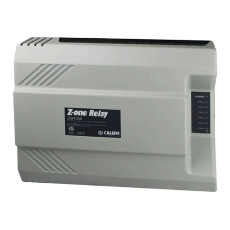
CALEFFI 115 Series Guide

CALEFFI

CALEFFI 115 Series Guide

CALEFFI 535H Series User guide

CALEFFI

CALEFFI 535H Series User guide

CALEFFI LEGIOMIX 6000 series Guide

CALEFFI

CALEFFI LEGIOMIX 6000 series Guide

CALEFFI SATK40 Series Guide

CALEFFI

CALEFFI SATK40 Series Guide

CALEFFI 5261 Series User manual

CALEFFI

CALEFFI 5261 Series User manual

CALEFFI PresCal 5355H Series User guide

CALEFFI

CALEFFI PresCal 5355H Series User guide

CALEFFI 146 Series Guide

CALEFFI

CALEFFI 146 Series Guide

CALEFFI 252169A Guide

CALEFFI

CALEFFI 252169A Guide

CALEFFI ThermoSetter 1164 Series User guide

CALEFFI

CALEFFI ThermoSetter 1164 Series User guide

CALEFFI 5218 Series User manual

CALEFFI

CALEFFI 5218 Series User manual

CALEFFI ThermoBloc 281 Series User manual

CALEFFI

CALEFFI ThermoBloc 281 Series User manual

CALEFFI 573 Series User manual

CALEFFI

CALEFFI 573 Series User manual

CALEFFI 501 Series User manual

CALEFFI

CALEFFI 501 Series User manual

CALEFFI 524 Series User manual

CALEFFI

CALEFFI 524 Series User manual

CALEFFI 574 series User manual

CALEFFI

CALEFFI 574 series User manual

CALEFFI 3048 Series User manual

CALEFFI

CALEFFI 3048 Series User manual

CALEFFI 5230 Series User manual

CALEFFI

CALEFFI 5230 Series User manual

CALEFFI 142 Series User manual

CALEFFI

CALEFFI 142 Series User manual

Popular Control Unit manuals by other brands

Ksenia lares 4.0 - 40 wls Installation and use manual

Ksenia

Ksenia lares 4.0 - 40 wls Installation and use manual

Avnera DNMA-83 user manual

Avnera

Avnera DNMA-83 user manual

Supermicro SBI-6419P-T3N user manual

Supermicro

Supermicro SBI-6419P-T3N user manual

Midland A-207 RE-ASSEMBLY INSTRUCTIONS

Midland

Midland A-207 RE-ASSEMBLY INSTRUCTIONS

National Instruments SCXI-1502 user manual

National Instruments

National Instruments SCXI-1502 user manual

Rain Bird 100-DV installation instructions

Rain Bird

Rain Bird 100-DV installation instructions

Mitsubishi Electric MELSEC Q Series user manual

Mitsubishi Electric

Mitsubishi Electric MELSEC Q Series user manual

Keysight M9032A Startup guide

Keysight

Keysight M9032A Startup guide

FrSky R9M 2019 instruction manual

FrSky

FrSky R9M 2019 instruction manual

Pratissoli S455 operating instructions

Pratissoli

Pratissoli S455 operating instructions

Kontron COMe-mAL10 user guide

Kontron

Kontron COMe-mAL10 user guide

Siemens 3VL9800-3MJ00 operating instructions

Siemens

Siemens 3VL9800-3MJ00 operating instructions

Panasonic SC-GU3-EU instruction manual

Panasonic

Panasonic SC-GU3-EU instruction manual

Rockwell Automation Allen-Bradley 1769-OF4 user manual

Rockwell Automation

Rockwell Automation Allen-Bradley 1769-OF4 user manual

EZI Controls Total Control URC Clipsal C-Bus user manual

EZI Controls

EZI Controls Total Control URC Clipsal C-Bus user manual

Evco EV3 300 Series manual

Evco

Evco EV3 300 Series manual

FAAC E604 manual

FAAC

FAAC E604 manual

Edwards PV10/16EK instruction manual

Edwards

Edwards PV10/16EK instruction manual

manuals.online logo
manuals.online logoBrands
  • About & Mission
  • Contact us
  • Privacy Policy
  • Terms and Conditions

Copyright 2025 Manuals.Online. All Rights Reserved.